AZ489FT5815
Motorola Solutions, Inc.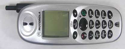
Click to zoom
Application Details
- Equipment Class
- TNE - Licensed Non-Broadcast Transmitter Held to Ear
- Date of Grant
- Dec 20, 2001
- Application Purpose
- Original Equipment
- Date of Application
- Sep 24, 2001
- Frequency Range
- 896.00000000 - 902.00000000
- Company
- Motorola Solutions, Inc.
- Country
- United States
Documents & Files
Document Text
Text extracted from the exhibit documents filed with the FCC. Open a document above to read the original.
Users Manual
Motorola iDEN ® Digital Multi-Service Data-Capable Phone i85s Phone User’s Guide @NTN9468C@ NTN9468-C www.motorola.com/iden 1 Table of Contents Table of Contents.................................................................................. 1 Introduction .......................................................................................... 7 Driving Safety Tips .........................................................................................9 Getting Started.................................................................................... 11 i85s Phone Features ......................................................................................12 Battery ...........................................................................................................12 Turning Your i85s Phone On/Off ................................................................15 Security Features of the i85s Phone ..............................................................16 Status of Your i85s Phone.............................................................................27 My Information .............................................................................................27 Using T9 Text Input ......................................................................................28 Display Essentials ............................................................................... 35 Display Screen Elements...............................................................................35 Navigating Menus and Lists..........................................................................39 Main Menu Options.......................................................................................40 Phonebook ........................................................................................... 43 Accessing Phonebook with an i2000, i2000plus, or GSM Phone.................44 Phonebook Entries and Speed Dial Numbers................................................44 Phonebook Icons ...........................................................................................44 Voice Names .................................................................................................45 Accessing Your Phonebook ..........................................................................45 About Phonebook Entries..............................................................................46 Pause Digit Entry...........................................................................................54 Plus Dialing ...................................................................................................55 Digital Cellular.................................................................................... 57 Making Phone Calls ......................................................................................57 Emergency Calling ........................................................................................62 2 www.motorola.com/iden Receiving a Phone Call .................................................................................63 Ending a Phone Call ......................................................................................63 Recent Calls...................................................................................................63 Call Timers ....................................................................................................66 Hands-Free Speakerphone.............................................................................67 Mute...............................................................................................................68 Call Waiting ..................................................................................................68 Call Hold .......................................................................................................70 Three-Way Calling ........................................................................................71 Call Forwarding.............................................................................................72 Messages .............................................................................................. 75 Message Center .............................................................................................75 Voice Mail .....................................................................................................76 Using Voice Mail ..........................................................................................77 Text and Numeric Messaging........................................................................78 Net Mail.........................................................................................................80 Using Your Phone as a Modem.....................................................................81 Private Calls ........................................................................................ 83 Private Call ....................................................................................................83 Call Alerts......................................................................................................85 Group Call .....................................................................................................89 Datebook.............................................................................................. 93 Datebook Icons..............................................................................................94 Viewing Your Datebook ...............................................................................94 About Datebook Events.................................................................................96 Adding New Events.......................................................................................97 Editing Events .............................................................................................101 Deleting Events ....…
Text truncated - open the document above for the full version.
Attestation Statements
FCC Filing Package for Motorola i85s, i50sx, i55srTransceiver FCC ID: AZ489FT5815 IDEN, Motorola Inc., 8000 W. Sunrise Blvd., Plantation, FL 33322, USA WWW.MOT.COM/iDEN Page: 2- 1 Exhibit 2. Statement of Certification -- Pursuant to 47 CFR 2.907 The technical data supplied with this application, having been taken under my supervision is hereby duly certified. The following is a statement of my qualifications: B.S. in Electrical Engineering, 1993, University of Puerto Rico 3 years experience in RF/EMI measurement NAME: Roberto Gautier SIGNATURE: Roberto Gautier DATE: 8/28/2001 POSITION: Electrical Engineer I hereby certify that the above application was prepared under my direction and that to the best of my knowledge and belief, the facts set forth in the application and accompanying technical data are true and correct: NAME: Erik Walls SIGNATURE: Erik Walls DATE: 8/28/2001 POSITION: Engineering Section Manager
Cover Letter(s)
Applicant: Motorola Inc FCC ID: AZ489FT5815 www.mot.com/iDEN iDEN, Motorola Inc., 8000 W. Sunrise Blvd., Plantation, FL 33322 Page: 13- 1 25 th September 2001 Authorization & Evaluation Division Federal Communications Commission Laboratory 7435 Oakland Mills Road Columbia, MD 21046 Gentlemen; Motorola Inc., 8000 West Sunrise Boulevard, Fort Lauderdale, Florida 33322, herein submits it’s application for Certification of the transmitter with FCC ID: AZ489FT5815. This variable power (0.24 to 700 milliwatt ERP) transmitter is part of a handheld transceiver used in a SMR and EA SMR trunking system operating in the United States 806-821/851-866MHz and 896- 902/935-941 MHz frequency band. Certification is sought for, and performance data is provided. This transceiver is of the receive-first type described in International Telecommunications Union Recommendation ITU-R M.1221 entitled Technical And Operational Requirements For Cellular Multimode Mobile Radio Stations. It must first find, acquire and lock onto a control channel from a predefined set of control channel frequencies assigned to a companion Authorized base station (e.g. – FCC ID: ABZ89FC5792). Transmission is not possible until lock to a base station control channel has been achieved, then transmission is limited to digitally modulated service request bursts on the reverse control channel. Upon recognition of a proper request, the control channel base station transmitter will then assign the transceiver a traffic channel for transmission of digital voice or circuit-switched data from the set of frequencies for which the trunking system is licensed. Attached Exhibit 12.1 provides additional descriptive details. It is expected that this handheld time division multiplexed transceiver marketed in the United States will also be used for itinerant operation with companion Authorized Base Stations by users requesting trunked radio and telephone interconnect service while roaming outside the United States. In some countries the companion base stations are licensed to operate at frequencies in the 821-825/866-870 MHz band in addition to some of those in the 806-821/851-866 MHz band normally used in United States SMR systems. Consequently, this transmitter has been designed to meet FCC requirements for operation in the 806-821 MHz band over the more global band of 806 - 825 MHz when used with a companion Authorized Base Station. Thus, performance data is provided to substantiate FCC compliant operation with a Companion Base Station over the broader 806 to 825 MHz band expected for global use of this handheld transceiver. To facilitate global roaming it is kindly requested that a note be provided in the Grant for Equipment Authorization, which states that this ‘receive first’ type of equipment is compliant for transmitter operation over the broader range 806-825 MHz when used with a compatible Authorized Base Station. This will aid equipment authorization in foreign countries, which accept a United States Applicant: Motorola Inc FCC ID: AZ489FT5815 www.mot.com/iDEN iDEN, Motorola Inc., 8000 W. Sunrise Blvd., Plantation, FL 33322 Page: 13- 2 FCC Grant for Equipment Authorization, yet not jeopardize United States public safety or cellular systems licensed to operate in the 821-825 MHz frequency band since no compatible base station may be authorized on those frequencies in the United States. It is also expected that this transceiver type will be marketed outside the United States and brought into the United States for itinerant “roaming” operation on compatible 806 - 821 MHz base stations located within the United States. Consequently, upon receipt of Authorization, only those units of this equipment type authorized for marketing in countries outside the United States will also bear a label with the specified FCC identifier. In accordance with 47 CFR 2.1093(c) this transmitter may be used in “covered” SMR service so it has been subjected to routine environmental evaluation for RF exposure and found to be compliant with the limits specified in 47 CFR 2.1093(d)(2). The subject transmitter complies with 47 CFR 90.203 of the rules in that the operator cannot directly program transmit frequencies using only the unit's normally accessible external controls. This transceiver can function as a Part 15.3(r) computer peripheral device when functioning as an RF modem when connected to a computer via a data cable (ref: Exhibit 12.1). In addition, this transceiver can function as a hand-held Part 15.3(k) computer executing application programs even when not connected to a companion trunked system base station control channel. Enclosed is a complete Certification application. Contact me at (954) 723-5793 if you require any additional information. Sincerely, /s/ Mike Ramnath FCC Liaison Email: [email protected]
Cover Letter(s)
Applicant: Motorola Inc. FCC ID: AZ489FT5815 Motorola Inc., 8000 W. Sunrise Blvd., Plantation, FL 33322 Page: 13-2 REQUEST FOR CONFIDENTIALITY 25th September 2001 Authorization & Evaluation Division Federal Communications Commission Laboratory 7435 Oakland Mills Road Columbia, MD 21046 Subject: Application for Type Acceptance of Transmitter with FCC ID: AZ489FT5815. Gentlemen; Motorola is requesting that Exhibit 4 (Circuit Description), Exhibit 5 (Schematic Diagrams), and Exhibit 10 (Semiconductor/Active Device List) not be made routinely available for public inspection. Motorola is in the process of licensing the technology and has a number of Patent applications pending. Please mark Exhibit 4, 5 and 10 as Confidential. Contact me at (954) 723-5793 if you require any additional information. Regards, /s/ Mike Ramnath FCC Liaison Email: [email protected]
Cover Letter(s)
DECLARATION OF CONFORMITY Per FCC CFR 47 Part 2 Section 2.1077(a) Responsible Party Name: Motorola, Inc. Address: 8000 West Sunrise Boulevard, Plantation, FL 33328 USA Phone Number: 1 (800) 453-0920 Hereby declares that the product: Product Name: i85s, i50sx, i55sr Model Number: H40XAH6RR1BN Conforms to the following regulations: FCC Part 15, subpart B, section 15.107(a), 15.107(d) and section 15.109(a) Class B Digital Device Date: Sep. 19, 2001 Note: This equipment has been tested and found to comply with the limits for a Class B digital device, pursuant to part 15 of the FCC Rules. These limits are designed to provide reasonable protection against harmful interference in a residential installation. This equipment generates, uses and can radiate radio frequency energy and, if not installed and used in accordance with the instructions, may cause harmful interference to radio communications. However, there is no guarantee that interference will not occur in a particular installation. If this equipment does cause harmful interference to radio or television reception, which can be determined by turning the equipment off and on, the user is encouraged to try to correct the interference by one or more of the following measures: --Reorient or relocate the receiving antenna. --Increase the separation between the equipment and receiver. --Connect the equipment into an outlet on a circuit different from that to which the receiver is connected. --Consult the dealer or an experienced radio/TV technician for help.
Cover Letter(s)
Date: 16 th November 2001 Mr. Joe Dichoso Authorization & Evaluation Division Federal Communications Commission Laboratory 7435 Oakland Mills Road Columbia, MD 21046 Re: Form 731 Confirmation Number: EA21096 with FCC ID: AZ489FT5815. Dear Mr. Dichoso; Motorola Inc., 8000 West Sunrise Boulevard, Fort Lauderdale, Florida 33322, herein submits its response to the October 30, 2001 request for information in Correspondence Number 21096. 1) The body worn phantom is made out of 1” thick natural High Density Polyethylene. The dimensions of the holder and the opening are shown below. The measured dielectric constant is less than 2.3 and the loss tangent is less than 0.0046 all the way up to 2.184GHz. Figure 1. Dimensions of the Body-Worn Phantom Support 2) The body-worn positioner is the same positioner used for the head adjacent measurements. The average measured dielectric constant is 3.29 and average measured loss tangent is 0.053 across the 800 MHz band. 3) An incorrect antenna description was inserted in the SAR report. The correct antenna description is the retractable half-wave antenna given in the operational description. The corrected description for the SAR report is shown below. Type Retractable Location Right Side Length 85mm Dimensions Width at Base 5mm Configuration Half-Wave 4) The SAR test measurement in the original filing was for the cheek/touch position only. The 15° tilt SAR measurement results are shown in the tables below. These measurements were taken within 24 hours of the previously reported phone mode head adjacent measurements. A full data set output of the test condition with the highest SAR values, per transmitting band, is attached at the end of this report. The test conditions included are indicated as bold numbers in the following tables. All other test conditions measured lower SAR values than those included. Left Head - 15° tilt Position Right Head - 15° tilt Position Antenna Extended Antenna Retracted Antenna Extended Antenna Retracted Description f (MHz) Conducted Output Power (dBm) SAR, 1g (W/kg) Drift (dB) SAR, 1g (W/kg) Drift (dB) SAR, 1g (W/kg) Drift (dB) SAR, 1g (W/kg) Drift (dB) 806.0125 28.3dBm 813.5125 28.4dBm 0.638 -0.28 0.715 -0.40 0.515 -0.18 0.541 -0.33 800MHz Phone Mode 824.9875 28.3dBm Table 1: SAR measurement results for the portable radio FCC ID AZ489FT5815 with Battery SNN5716A attached, at highest possible output power. Measured against the head. Left Head - 15° tilt Position Right Head - 15° tilt Position f Antenna Extended Antenna Retracted Antenna Extended Antenna Retracted Description (MHz) Conducted Output Power (dBm) SAR, 1g (W/kg) Drift (dB) SAR, 1g (W/kg) Drift (dB) SAR, 1g (W/kg) Drift (dB) SAR, 1g (W/kg) Drift (dB) 896.01875 28.3dBm 898.49375 28.3dBm 0.471 -0.32 0.518 -0.28 0.316 -0.33 0.459 -0.22 900MHz Phone Mode 901.9875 28.3dBm Table 2: SAR measurement results for the portable radio FCC ID AZ489FT5815 with Battery SNN5716A attached, at highest possible output power. Measured against the head. 5) In the body-worn configuration, the headset and not the data cable was used for all configurations because it can be seen in the original SAR report in tables 10 & 11 that this causes the maximum measured SAR. The use of the data cable actually lowers SAR. The data cable was utilized only for the peak SAR configuration in order to show how use of this accessory impacts measured SAR. 6) It is believed that the RF current distribution is different for the body worn configuration vs. the head adjacent testing. This may cause the antenna retracted SAR to be lower than expected. Another unit (serial number 919ABL5CYC) was tested for head adjacent SAR at the same time to see if it was repeatable from unit to unit. It was determined that this effect is repeatable and can be seen from the SAR measurement results shown in the table below. Left Head Right Head f Antenna Extended Antenna Retracted Antenna Extended Antenna Retracted Description (MHz) Conducted Output Power (dBm) SAR, 1g (W/kg) Drift (dB) SAR, 1g (W/kg) Drift (dB) SAR, 1g (W/kg) Drift (dB) SAR, 1g (W/kg) Drift (dB) 896.01875MHz 28.3dBm 1.1 -0.15 1.03 -0.31 898.49375MHz 28.3dBm 0.271 -0.06 1.1 -0.2 0.288 -0.16 1.03 -0.17 900MHz PSTN 901.9875MHz 28.3dBm 1.07 -0.17 0.948 -0.19 Table 3: SAR measurement results for the portable radio FCC ID AZ489FT5815 with Battery SNN5716A attached, at highest possible output power. Measured against the head. 8) We are obtaining the needed equipment to monitor and report temperature of the tissue simulant before and after each SAR tests, and not just during the validation tests. We do currently monitor and record the room ambient temperature to verify that it does not drift by more than ±2.0°C from the temperature measured in the morning. 9) ERP data was inadvertently omitted in the original submission and is attached as new Exhibit 6.7. The graph therein shows that the spatial peak value obtained while the transmitter was mounted on a platform during rotation in an anechoic chamber, using the substitution method described in Exhibit 7.2(b), occurred at the rotational angle of 126 degrees when measured in the 800 MHz band. In the 900 MHz band the spatial peak value was observed at an angle of 176 degrees. In Exhibit 12.1.C we have used the term “maximum ERP” to refer to this spatial peak value measured for a continuous wave signal corresponding to 100% duty cycle. 10) a) 700 milliwatts is stated in Exhibits 12.1.A and new Exhibit 6.7 as the maximum output power rating, based on the requirement of 2.1046(a) and the definition of output power given in 47 CFR 90.7, as power delivered to a 50 ohm impedance (which is the load the antenna system is designed to provide). It is the maximum average power measured during the interval of a TDM transmission pulse, so we adopted the term pulse average power for this rating. Note that this mean power type of rating is unaffected by the various TDM duty cycles employed so it also is equal to the mean power that would be…
Text truncated - open the document above for the full version.
Cover Letter(s)
Date: 14 th December 2001 Mr. Joe Dichoso Authorization & Evaluation Division Federal Communications Commission Laboratory 7435 Oakland Mills Road Columbia, MD 21046 Re: Form 731 Confirmation Number: EA102539 with FCC ID: AZ489FT5815. Dear Mr. Dichoso; Motorola Inc., 8000 West Sunrise Boulevard, Fort Lauderdale, Florida 33322, herein submits its response to the 10 th December 2001 request for information in Correspondence Number 21384 and 21385. We are sorry if our terminology is causing confusion, so first we wish to clarify the way we use these terms as that should eliminate the confusion. We use the word “maximum” to distinguish the highest numerical value measured, regardless of the measurement means. RF power measurement is generally done with an average reading (RMS) power meter such as the Hewlett Packard HP437B which we list in the equipment list of Exhibit 7.6; but it can also be performed with a peak reading power meter (e.g. – a Boonton 4500). We use the term “average” to denote that the power measurement is performed using an average-reading (or RMS) power meter to obtain a mean power resultant (as defined in 47 CFR 2.1) by averaging over a period long compared to the signal fluctuations due to modulation. Since output power is zero except during the TDM transmission pulse we report power readings that are time-synchronized to exclude the non-transmission period. In that manner the average power reading is not reduced by the off period of the TDM duty cycle. The term we elected to use to describe this measurement method is “pulse average”. Stating power in this way also has proven to be very practical for predicting communication system coverage and operator licensing, and has the advantage of a value that is duty cycle independent. Regarding your request for peak values, for a pure sine wave signal like that from an FM transmitter a peak reading meter will report a Peak Envelope Power (as defined in 47 CFR 2.1) value 1.41 times greater than that reported as Mean Power by the average-reading meter. In the case of our Quad QAM signal this peak-to-average ratio is 3.67 (or equivalently, 5.65 dB). This peak-to-average ratio is a factor that can be used to scale all the pulse average power data we have reported. Given the above clarifications we believe that what you seek is the maximum values for statement in a Grant based on average power measurements, not the peak Envelope Power values, so the following answers are respectfully provided to your questions. 1) The maximum output power (pulse average) that would be measured at the antenna terminals is 700 milliwatts (or equivalently, 28.45 dBm). We rate the radio at 600 milliwatts (27.78 dBm) output power, with unit-to-unit operational variation extremes limited to the 700 milliwatt maximum. Our radio is rated by output power, rather than ERP, to assure compliance with the output power limits given in 47 CFR 90.635(d; and, that is our preference for a Grant of Authorization. 2) The measured maximum ERP reported in Exhibit 6.7 was 871 milliwatts (pulse average). This value is based on scaling to 700 milliwatts the output power of an ERP test radio with an output power of 679 milliwatts (as reported at the top of the 900 MHz segment of the ERP Data table in Exhibit 6.7). Unfortunately, the heading of those columns of the Data Table were inadvertently mislabeled with the test frequency, rather than labeled Maximum Calculated ERP as we have done in the past for applications you have previously reviewed (e.g. - AZ489FT5808). Be advised that, during the relatively short (about 1 minute) duration of the ERP measurement in the RF anechoic chamber, output power is essentially constant (within 1% from start to finish). Since there is little benefit in measuring output power at each angular position under this condition or power stability, it was not done. 3) Differing output power values appear in the data supplied because different units were involved; but all are consistent with our rating and expected unit-to- unit variations. In particular, for compliance with the OET 65 Supplement C Edition 01-01 guidelines, the units used for SAR and ERP tests were within 5% of the maximum rated output power. It is noted that the 5% variation tolerated in Edition 01-01 differs from the 20% variation tolerated in 47 CFR 90.205(0). Contact me at (954) 723-5793 if you require any additional information. Regards, /s/ Mike Ramnath FCC Liaison Email: [email protected]
External Photos
FCC Filing Package for Motorola i85s, i50sx, i55srTransceiver FCC ID: AZ489FT5815 IDEN, Motorola Inc., 8000 W. Sunrise Blvd., Plantation, FL 33322, USA WWW.MOT.COM/iDEN Page: 3 - 1 Exhibit 3. External Photographs -- Pursuant to 47 CFR 2.1033(c)12 The different model variations (i85s, i50sx, i55sr) will have identical back view and labeling. Keypad shapes and front housing / bezel colors vary with none having more than 3.0% metallic content. Photograph 3-1: Back view, antenna retracted with battery cover. Photograph 3-2: Back view, antenna retracted, no battery cover . FCC Filing Package for Motorola i85s, i50sx, i55srTransceiver FCC ID: AZ489FT5815 IDEN, Motorola Inc., 8000 W. Sunrise Blvd., Plantation, FL 33322, USA WWW.MOT.COM/iDEN Page: 3 - 2 Photograph 3-4: i85s front view, antenna retracted Photograph 3-5: i85s front view, antenna extended. Photograph 3-6: i85s button side view, antenna retracted. Photograph 3-7: i85s no button side view, antenna retracted. FCC Filing Package for Motorola i85s, i50sx, i55srTransceiver FCC ID: AZ489FT5815 IDEN, Motorola Inc., 8000 W. Sunrise Blvd., Plantation, FL 33322, USA WWW.MOT.COM/iDEN Page: 3 - 3 Photograph 3-8: i50sx front view, antenna retracted. Photograph 3-9: i50sx front view, antenna extended. Photograph 3-10: i50sx button side view, antenna retracted. Photograph 3-11: i50sx no button side view, antenna retracted. FCC Filing Package for Motorola i85s, i50sx, i55srTransceiver FCC ID: AZ489FT5815 IDEN, Motorola Inc., 8000 W. Sunrise Blvd., Plantation, FL 33322, USA WWW.MOT.COM/iDEN Page: 3 - 4 Photograph 3-12: i55sr front view, antenna retracted. Photograph 3-13: i55sr front view, antenna extended. Photograph 3-14: i55sr button side view, antenna retracted. Photograph 3-15: i55sr no button side view, antenna retracted.
ID Label/Location Info
FCC Filing Package for Motorola i85s, i50sx, i55srTransceiver FCC ID: AZ489FT5815 IDEN, Motorola Inc., 8000 W. Sunrise Blvd., Plantation, FL 33322, USA WWW.MOT.COM/iDEN Page: 1- 1 Exhibit 1. Identification Label -- Pursuant to 47 CFR 2.925, 2.1065 and 2.1033(c)11 1.1. Location Back side of the transceiver unit chassis. (See the attached photograph 3.5 in exhibit 3) 1.2. Type The label is a white polyester film laminate with a pressure sensitive adhesive backing. The adhesive is a permanent type acrylic with minimum peel strength of 5 lbs/in. 1.3. Markings (Text) Enlarged view of label (showing FCC ID and manufacturer type number): Figure 1.1: Label positions on unit's back housing. FCC Filing Package for Motorola i85s, i50sx, i55srTransceiver FCC ID: AZ489FT5815 IDEN, Motorola Inc., 8000 W. Sunrise Blvd., Plantation, FL 33322, USA WWW.MOT.COM/iDEN Page: 1- 2 Figure 1.2: Zoom in of label containing FCC ID Figure 1.3: Zoom in of label containing FCC Logo
ID Label/Location Info
FCC Filing Package for Motorola i85s, i50sx, i55srTransceiver FCC ID: AZ489FT5815 IDEN, Motorola Inc., 8000 W. Sunrise Blvd., Plantation, FL 33322, USA WWW.MOT.COM/iDEN Page: 1- 1 Exhibit 1A. General Information 1A.1. Production Plans Quantity production is planned. 1A.2. Application References -- Pursuant to 47 CFR 2.948 and 2.1061 Reference is made to the following Motorola "Application References" 1. Open Area Test Site “OATS” FCC Registration: 91932 Industry of Canada: IC3679 2. ISO / IEC Guide 25-1990 accredited by The American Association For Laboratory Accreditation (A2LA) Motorola EMC Lab. 1A.3. Data Submittal Procedure Data located in Exhibit 6 is supplied in accordance with 47CFR2, Sub-part J and Part 90, Sub-parts I and Sub-part S of the Commission’s rules. Declaration of Conformity in page 6 of User's Manual in Exhibit 8 is provided in accordance with 47CFR2.1077(a). 1A.4. Similar, currently Certified Transceiver FCC ID: AZ489FT5799 and AZ489FT5789 1A.5. Additional Considerations This transceiver can function as a Part 15.3(r) computer peripheral device when functioning as an RF modem when connected to a computer via a data cable accessory (ref: Exhibit 12.1). In addition, this transceiver can function as a hand-held Part 15.3(k) computer executing application programs even when not connected to a companion trunked system base station control channel. A Declaration of Conformity is provided in Exhibit 8 as evidence of compliance with Part 15 requirements for these additional Class B digital device functionalities per 47 CFR 15.101(a). Compliance with Part 15 requirements for the superheterodyne receiver has been determined by verification in accordance with 47CFR15.1.
Internal Photos
FCC Filing Package for Motorola i85s, i50sx, i55srTransceiver FCC ID: AZ489FT5815 IDEN, Motorola Inc., 8000 W. Sunrise Blvd., Plantation, FL 33322, USA WWW.MOT.COM/iDEN Page: 9- 1 Exhibit 9. Internal Photographs -- Pursuant to 47 CFR 2.1033(c)12 Photograph 9-1: Front of keypad / speaker board. Photograph 9-2: Back side of keypad board. FCC Filing Package for Motorola i85s, i50sx, i55srTransceiver FCC ID: AZ489FT5815 IDEN, Motorola Inc., 8000 W. Sunrise Blvd., Plantation, FL 33322, USA WWW.MOT.COM/iDEN Page: 9- 2 Photograph 9-3: Front side of radio main board inside back housing. Photograph 9-4: Front side of radio main board without factory applied shields. FCC Filing Package for Motorola i85s, i50sx, i55srTransceiver FCC ID: AZ489FT5815 IDEN, Motorola Inc., 8000 W. Sunrise Blvd., Plantation, FL 33322, USA WWW.MOT.COM/iDEN Page: 9- 3 Photograph 9-5: Back side of radio main bo…
Text truncated - open the document above for the full version.
Contact Information
Applicant
Deanna Zakharia(Regulatory Compliance Manager)
Technical Contact
Motorola IncMike Ramnath
[email protected]954-723-5793
8000 West Sunrise Blvd · Ft.Lauderdale, Florida · United States
Technical Specifications
| # | Rule Parts | Frequency Range | Power Output | Emission | Tolerance |
|---|---|---|---|---|---|
| 2 | 9 | 896 MHz - 902 MHz | 700.00 mW | 18K3D7W | 0.5 ppm |
Other Applications from Motorola Solutions, Inc.

AZ489FT4980
Sep 08, 2026Portable two way radio
Equipment Class
TNF - Licensed Non-Broadcast Transmitter Held to FaceAZ489FT4981
Aug 14, 2026Handheld Portable - TANAPA BPR 45 400-470 MHZ 4W NKP
Equipment Class
TNF - Licensed Non-Broadcast Transmitter Held to Face
AZ489FT7187
Jul 13, 2026Portable 2-Way Radio with Bluetooth, Bluetooth LE, WIFI 2.4GHz, WIFI 5GHz, LTE
Equipment Class
DSS - Part 15 Spread Spectrum TransmitterAZ499FT6031
May 11, 2026Operation Critical Wireless Earpiece PTT
Equipment Class
DSS - Part 15 Spread Spectrum Transmitter
AZ499FT5879
Dec 19, 20252-way Portable Radio with BT, BTLE, WIFI, NFC and LTE
Equipment Class
DSS - Part 15 Spread Spectrum Transmitter