AZ489FT5818iDEN i30sx
Motorola Solutions, Inc.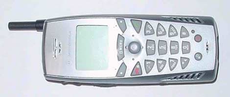
Click to zoom
Application Details
- Equipment Class
- TNE - Licensed Non-Broadcast Transmitter Held to Ear
- Date of Grant
- Mar 20, 2002
- Application Purpose
- Original Equipment
- Date of Application
- Dec 18, 2001
- Equipment Note
- iDEN i30sx
- Frequency Range
- 896.00000000 - 901.00000000
- Company
- Motorola Solutions, Inc.
- Country
- United States
Documents & Files
Document Text
Text extracted from the exhibit documents filed with the FCC. Open a document above to read the original.
Users Manual
Motorola iDEN ® Digital Multi-Service Data-Capable Phone i30sxPhone User’s Guide Preliminary @NNTN4196A@ NNTN4196A www.motorola.com/iden i Table of Contents Introduction .......................................................................................... 5 Driving Safety Tips .........................................................................................6 Getting Started...................................................................................... 9 i30sxPhone Features ..................................................................................... 10 Battery ........................................................................................................... 10 Turning Youri30sxPhone On/Off ............................................................... 14 Security Features of thei30sxPhone ............................................................ 15 Keypad Lock .................................................................................................21 Status of Youri30sxPhone ...........................................................................24 My Information ............................................................................................. 25 Using T9® Text Input ...................................................................................26 Display Essentials ............................................................................... 31 Display Screen Elements ............................................................................... 31 Call Information Icons...................................................................................34 Navigating Menus and Lists .......................................................................... 35 Main Menu Options....................................................................................... 36 Phonebook ........................................................................................... 39 Accessing Phonebook with ani2000,i2000plus, or GSM Phone .................40 Phonebook Entries and Speed Dial Numbers................................................ 40 Phonebook Icons ........................................................................................... 40 Voice Names .................................................................................................41 Accessing Your Phonebook .......................................................................... 41 About Phonebook Entries..............................................................................42 Pause Digit Entry........................................................................................... 49 Plus Dialing ................................................................................................... 51 Digital Cellular.................................................................................... 53 Making Phone Calls ......................................................................................53 Emergency Calling ........................................................................................ 58 ii www.motorola.com/iden Receiving a Phone Call .................................................................................58 Ending a Phone Call ......................................................................................58 Recent Calls................................................................................................... 58 Call Timers .................................................................................................... 62 Call Waiting .................................................................................................. 63 Call Hold ....................................................................................................... 65 Three-Way Calling ........................................................................................ 66 Call Forwarding............................................................................................. 68 Messages .............................................................................................. 73 Message Center ............................................................................................. 73 Voice Mail ..................................................................................................... 74 Using Voice Mail .......................................................................................... 75 Text and Numeric Messaging........................................................................76 Net Mail.........................................................................................................78 Using Your Phone as a Modem.....................................................................79 Private Calls ........................................................................................ 81 Private Call .................................................................................................... 81 Call Alerts...................................................................................................... 83 Group Call ..................................................................................................... 87 Memo ................................................................................................... 91 Adding a New Memo .................................................................................... 91 Viewing a Memo ........................................................................................... 91 Editing a Memo ............................................................................................. 92 Deleting a Memo ........................................................................................... 92 Customizing thei30sx phone ............................................................. 93 Settings ........................................................................................…
Text truncated - open the document above for the full version.
Attestation Statements
FCC Filing Package for Motorola i30sxTransceiver FCC ID: AZ489FT5818 IDEN, Motorola Inc., 8000 W. Sunrise Blvd., Plantation, FL 33322, USA WWW.MOT.COM/iDEN Page: 2- 1 Exhibit 2. Statement of Certification -- Pursuant to 47 CFR 2.907 The technical data supplied with this application, having been taken under my supervision is hereby duly certified. The following is a statement of my qualifications: BS. In Physics and Math, 1984, Hebei Teachers University MS. in Electrical and Computer Engineering, 1999, University of Florida MS. In Nuclear and Radiological Engineering, 1998, University of Florida 2 years experience in RF/EMI measurement NAME: Caijun Sun SIGNATURE: /s/ Caijun Sun DATE: 12/17/2001 TITLE: Senior Electrical Engineer I hereby certify that the above application was prepared under my direction and that to the best of my knowledge and belief, the facts set forth in the application and accompanying technical data are true and correct: NAME: Andy Molina SIGNATURE: /s/ Andy Molina DATE: 12/17/2001 TITLE: Engineer Manager
Cover Letter(s)
Applicant: Motorola Inc FCC ID: AZ489FT5818 iDEN, Motorola Inc., 8000 W. Sunrise Blvd., Plantation, FL 33322 www.mot.com/iDEN Page: 13- 1 18 th December 2001 Authorization & Evaluation Division Federal Communications Commission Laboratory 7435 Oakland Mills Road Columbia, MD 21046 Gentlemen; Motorola Inc., 8000 West Sunrise Boulevard, Fort Lauderdale, Florida 33322, herein submits it’s application for Certification of the transmitter with FCC ID: AZ489FT5818. This variable output power (0.199 to 700 milliwatt) transmitter is part of a handheld transceiver used in a SMR and EA SMR trunking system operating in the United States 806-821/851-866MHz and 896-901/935-940 MHz frequency band. Certification is sought for this transceiver, and performance data is provided for that purpose. This transceiver is of the receive-first type described in International Telecommunications Union Recommendation ITU-R M.1221 entitled Technical And Operational Requirements For Cellular Multimode Mobile Radio Stations. It must first find, acquire and lock onto a control channel from a predefined set of control channel frequencies assigned to a companion Authorized base station (e.g. – FCC ID: ABZ89FC5792). Transmission is not possible until lock to a base station control channel has been achieved, then transmission is limited to digitally modulated service request bursts on the reverse control channel. Upon recognition of a proper request, the control channel base station transmitter will then assign the transceiver a traffic channel for transmission of digital voice or circuit-switched data from the set of frequencies for which the trunking system is licensed. Attached Exhibit 12.1 provides additional descriptive details. It is expected that this handheld time division multiplexed transceiver marketed in the United States will also be used for itinerant operation with companion Authorized Base Stations by users requesting trunked radio and telephone interconnect service while roaming outside the United States. In some countries the companion base stations are licensed to operate at frequencies in the 821-825/866-870 MHz band in addition to some of those in the 806-821/851- 866 MHz band normally used in United States SMR systems. Consequently, this transmitter has been designed to meet FCC requirements for operation in the 806-821 MHz band over the more global band of 806 - 825 MHz when used with a companion Authorized Base Station. Thus, performance data is provided to substantiate FCC compliant operation with a Companion Base Station over the broader 806 to 825 MHz band expected for global use of this handheld transceiver. To facilitate global roaming it is kindly requested that a note be provided in the Grant for Equipment Authorization, which states that this ‘receive first’ type of equipment is compliant for Applicant: Motorola Inc FCC ID: AZ489FT5818 iDEN, Motorola Inc., 8000 W. Sunrise Blvd., Plantation, FL 33322 www.mot.com/iDEN Page: 13- 2 transmitter operation over the broader range 806-825 MHz when used with a compatible Authorized Base Station. This will aid equipment authorization in foreign countries, which accept a United States FCC Grant for Equipment Authorization, yet not jeopardize United States public safety or cellular systems licensed to operate in the 821-825 MHz frequency band since no compatible base station may be authorized on those frequencies in the United States. It is also expected that this transceiver type will be marketed outside the United States and brought into the United States for itinerant “roaming” operation on compatible 806 - 821 MHz base stations located within the United States. Consequently, upon receipt of Authorization, only those units of this equipment type authorized for marketing in countries outside the United States will also bear a label with the specified FCC identifier. In accordance with 47 CFR 2.1093(c) this transmitter may be used in “covered” SMR service so it has been subjected to routine environmental evaluation for RF exposure and found to be compliant with the limits specified in 47 CFR 2.1093(d)(2). The subject transmitter complies with 47 CFR 90.203 of the rules in that the operator cannot directly program transmit frequencies using only the unit's normally accessible external controls. This transceiver can function as a Part 15.3(r) computer peripheral device when functioning as an RF modem when connected to a computer via a data cable (ref: Exhibit 12.1). For this reason a Declaration of Conformity has been prepared and is provided on Page 6 of the user Manual in the Exhibit 8. Enclosed is a complete Certification Application comprised of 12 Exhibits. Contact me at (954) 723-5793 if you require any additional information. Sincerely, /s/Mike Ramnath FCC Liaison Email: [email protected]
Cover Letter(s)
Applicant: Motorola Inc. FCC ID: AZ489FT5818 Motorola Inc., 8000 W. Sunrise Blvd., Plantation, FL 33322 Page: 13-2 REQUEST FOR CONFIDENTIALITY 19th December 2001 Authorization & Evaluation Division Federal Communications Commission Laboratory 7435 Oakland Mills Road Columbia, MD 21046 Subject: Application for Type Acceptance of Transmitter with FCC ID: AZ489FT5818. Gentlemen; Motorola is requesting that Exhibit 4 (Circuit Description), Exhibit 5 (Schematic Diagrams), and Exhibit 10 (Semiconductor/Active Device List) not be made routinely available for public inspection. Motorola is in the process of licensing the technology and has a number of Patent applications pending. Please mark Exhibit 4, 5 and 10 as Confidential. Contact me at (954) 723-5793 if you require any additional information. Regards, /s/ Mike Ramnath FCC Liaison Email: [email protected]
Cover Letter(s)
FCC ID: AZ489FT5818 Date: 1st March 2002 Mr. Martin Perrine Authorization & Evaluation Division Federal Communications Commission Laboratory 7435 Oakland Mills Road Columbia, MD 21046 Re: Form 731 Confirmation Number: EA823993 with FCC ID: AZ489FT5818. Dear Mr. Perrine; Motorola Inc., 8000 West Sunrise Boulevard, Fort Lauderdale, Florida 33322, herein submits its response to the 27 February 2002 request for information in Correspondence Number 22103. 1) The transmitter is capable of being tuned to operate over the frequency range from 806 to 825 MHz to support both domestic and foreign operation. Operating frequency within that range is controlled by signaling from the licensed base station. This equipment is precluded from operation in the USA up to 825 MHz since no companion base stations have or can be licensed there under part 90. We rate this equipment by RF output power, not ERP. Output power is tuned at the factory, as noted in Exhibit 4.4, using special software not available to operators. Output power is tuned, in discrete steps via a step attenuator in integrated circuit U506 (see Figures 4.3 and 4.4), to the rated value of 0.60 watts. Considering manufacturing variations we rate output power as 0.70 watts maximum. Because of the resolution of the step attenuators it is not likely that any particular radio can be set exactly to the maximum limit. 2) The requested block diagram is provided in attached new Exhibit 4.6. 3) An attenuator of 10 dB was inserted between the spectrum analyzer and the test radio that was functioning at the normal operating power level circa 27.8 dBm. This reduces the signal into the analyzer to a level of 17.8 dBm. This is the level that might have been displayed except for the fact that the occupied bandwidth measurement utilized the peak hold feature of the spectrum analyzer, and the signal has a peak to average ratio on the order of 5.7 dB. This brings the expected display value to 23.5 dBm. We attribute the difference between this expectation and the actual displayed levels to attenuator and spectrum analyzer accuracy uncertainties. FCC ID: AZ489FT5818 4) CW is used for ERP measurements for best results with the antenna measurement system utilized. Special test software is loaded to generate this single carrier signal compared to the normal four subcarrier signal produced by digitally modulating the in-phase (I) and quadrature (Q) component signals shown in Figure 4-3. CW modulation is produced using special test software by disabling the modulation inputs to U801, and setting the attenuator for the Q channel to a maximum so only a single I-channel signal emanates from U506. Prior to ERP testing the radio output power is measured using a power meter while the I- channel attenuator setting is specially adjusted to a level closest to that produced by the radio when it is digitally modulated in normal operation. Due to attenuator resolution the output power so set will be close to, but not exactly equal to, that measured with normal digital modulation operational software or the maximum power rating. Because the output power so set is not exactly equal to the maximum output power rating then the ERP measured with the test radio needs to be scaled to the rated value by the ratio of rated digitally modulated output power to measured CW output power. For this reason Exhibits 6.8.1 and 6.8.2 contain the calculation process by which this is done for ERP measurement using the substitution antenna method. 5) All radiated spurious emissions were measured employing a peak detector while utilizing the Max Hold function on the Rohde & Schwarz ESI 26 EMI Test Receiver/Spectrum Analyzer stated in Exhibit 7.6.1. The Max Hold function saves for each sweep the largest of the previously stored/currently measured values in the trace memory. Using Max Hold, the detector is automatically set to Max Peak. The maximum spurious power level at each frequency is captured by virtue of the fact that the transmission pulses are peak detected at the analyzer at a rate faster than the rate at which the transmitter angular and search antenna vertical positioning vary. Further, the following information is provided regarding your inquiry on the SAR Report in Exhibit 11. 1) When a wrist strap is used, the intended position of the DUT is to be hanging below the user's wrist towards the user's hand. The wrist and hand have a SAR limit of 4.0 W/kg averaged over any 10g of tissue. During the FCC - TCB training workshop held during August 25-27, 2001, it was indicated that, because there has not been any issues with demonstrating SAR compliance in the hand, this would not be requested for future submissions. Also, there are no measurement procedure guidelines for measuring SAR in the hand or wrist stated in OET Bulletin 65 Supplement C. 2) The term Conducted Output Power level used on pages 4 through 8 corresponds to the output power of the unit assessed when measured on a conducted basis in the manner stated in Exhibit 7.1. The attenuator for that radio was set to provide FCC ID: AZ489FT5818 the highest attainable output power below the rated 700 milliWatt (28.45 dBm) rating. All power levels reported at the stated test frequencies were within the 5% power setting allowance stated in Supplement C Edition 01-01. 3) We confirm that faceplates other than the silver faceplates have a non-metallic finish. 4) Retractable half-wave antenna number 8504163G02 is an integral antenna supplied with the radio. No external antenna is offered. Information requested on our only hands free accessory (for in-vehicle use) is provided in attached new Exhibit 12.4. The need for audio impedance information is not clear, but per your request be advised that it is 32 ohms, except the neckloop is 1000 ohms. 5) There is a section in the user manual near the verbiage cited that is entitled Approved Accessories. That section was provided to assure that, consistent with your concern, information obtained by an intere…
Text truncated - open the document above for the full version.
Cover Letter(s)
FCC ID: AZ489FT5818 IDEN, Motorola Inc., 8000 W. Sunrise Blvd., Plantation, FL 33322, USA WWW.MOT.COM/ Page 6A-1 Date: 18th March 2002 Mr. Martin Perrine Authorization & Evaluation Division Federal Communications Commission Laboratory 7435 Oakland Mills Road Columbia, MD 21046 Re: Form 731 Confirmation Number: EA823993 with FCC ID: AZ489FT5818. Dear Mr. Perrine; Motorola Inc., 8000 West Sunrise Boulevard, Fort Lauderdale, Florida 33322, herein submits its response to the 13 March 2002 request for information in Correspondence Number 22299. Additional spurious emission measurements were performed with the unit terminated, as requested, in its integral antenna rather than the dummy load specified in ANSI/TIA/EIA-603-A §2.2.12.2. The resulting data is provided in the requested dBc format in attached Exhibit 6.4 Addendum. The power measured with a vertically polarized antenna from the radio test specimen operating at 27.8 dBm rated power in its normal vertical position is taken as the 0dB reference level. For clarity, not shown are values more than 23 dB below the 43 + 10 log(P) permissible level of -40.8 dBc (43- (30-27.8)), or limited by the noise figure of the spectrum analyzer. This data was obtained for the 3 different modulations employed during normal operation; quad 16-QAM, quad 64-QAM and QPSK. Within measurement uncertainty, the data shows that the type of digital modulation had no effect on the strength of the spurious emissions. Contact me at (954) 723-5793 if you require any additional information. Sincerely, /s/ Mike Ramnath FCC Liaison Email: [email protected] Attachment: Exhibit 6.4 Addendum, Radiated Spurious Emissions Data. FCC ID: AZ489FT5818 IDEN, Motorola Inc., 8000 W. Sunrise Blvd., Plantation, FL 33322, USA WWW.MOT.COM/ Page 6A-2 Exhibit 6.4 Addendum, Radiated Spurious Emissions Data. NOTE 1: The unit was measured with settings to produce rated output power (600 mw nominal) with automatic power cutback disabled. NOTE 2: An asterisk (*) in the data indicates the spurious emission was more than 23 below the maximum permitted level (-40.8 dBc), or could not be detected due to noise limitations. FCC ID: AZ489FT5818 IDEN, Motorola Inc., 8000 W. Sunrise Blvd., Plantation, FL 33322, USA WWW.MOT.COM/ Page 6A-3 Transmitter Radiated Spurious Emissions: (Vertical) 806.0625 MHz Vertical Measured Radiated Emission Power with internal Antenna (dBc) Spur Frequency (MHz) QAM_64 QAM_16 QPSK Fund 806.0625 0 0 0 IF 154.65 * * * 2 X IF 309.3 * * * LO 960.7125 * * * IF + LO 1115.3625 * * * 2XFund 1612.125 * * * 3XFund 2418.1875 * * * 4XFund 3224.25 * * * 5XFund 4030.3125 * * * 6XFund 4836.375 * * * 7XFund 5642.4375 * * * 8XFund 6448.5 * * * 9XFund 7254.5625 * * * 10XFund 8060.625 * * * Radiated Emissions (Vertical Polarization) -64 -56 -48 -40 -32 -24 -16 -8 0 806.0625154.6500309.3000960.7125 1115.36251612.12502418.18753224.25004030.31254836.37505642.43756448.50007254.56258060.6250 Frequency (MHz) Emission Level (dBc) QAM_64 QAM_16 QPSK FCC ID: AZ489FT5818 IDEN, Motorola Inc., 8000 W. Sunrise Blvd., Plantation, FL 33322, USA WWW.MOT.COM/ Page 6A-4 Transmitter Radiated Spurious Emissions: (Horizontal) 806.0625 MHz Horizontal Measured Radiated Emission Power with internal Antenna (dBc) Spur Frequency (MHz) QAM_64 QAM_16 QPSK Fund 806.0625 -15.55 -16.75 -18.19 IF 154.65 * * * 2 X IF 309.3 * * * LO 960.7125 * * * IF + LO 1115.3625 * * * 2XFund 1612.125 * * * 3XFund 2418.1875 -62.87 * -62.33 4XFund 3224.25 * * * 5XFund 4030.3125 * * * 6XFund 4836.375 * * * 7XFund 5642.4375 * * * 8XFund 6448.5 * * * 9XFund 7254.5625 * * * 10XFund 8060.625 * * * Radiated Emissions (Horizontal Polarization) -64 -56 -48 -40 -32 -24 -16 -8 0 806.0625154.6500309.3000960.7125 1115.36251612.12502418.18753224.25004030.31254836.37505642.43756448.50007254.56258060.6250 Frequency (MHz) Emission Level (dBc) QAM_64 QAM_16 QPSK FCC ID: AZ489FT5818 IDEN, Motorola Inc., 8000 W. Sunrise Blvd., Plantation, FL 33322, USA WWW.MOT.COM/ Page 6A-5 Transmitter Radiated Spurious Emissions: (Vertical) 900.98125 MHz Vertical Measured Radiated Emission Power with internal Antenna (dBc) Spur Frequency (MHz) QAM_64 QAM_16 QPSK Fund 900.98125 0 0 0 IF 154.65 * * * 2 X IF 309.3 * * * LO 960.7125 * * * IF + LO 1115.3625 * * * 2XFund 1612.125 * * * 3XFund 2418.1875 * * * 4XFund 3224.25 * * * 5XFund 4030.3125 * * * 6XFund 4836.375 * * * 7XFund 5642.4375 * * * 8XFund 6448.5 * * * 9XFund 7254.5625 * * * 10XFund 8060.625 * * * Radiated Emissions (Vertical Polarization) -64 -56 -48 -40 -32 -24 -16 -8 0 900.98125 154.6500309.3000 1055.63131210.28131801.96252702.94383603.92504504.90635405.88756306.86887207.85008108.83139009.8125 Frequency (MHz) Emission Level (dBc) QAM_64 QAM_16 QPSK FCC ID: AZ489FT5818 IDEN, Motorola Inc., 8000 W. Sunrise Blvd., Plantation, FL 33322, USA WWW.MOT.COM/ Page 6A-6 Transmitter Radiated Spurious Emissions: (Horizontal) 900.98125 MHz Horizontal Measured Radiated Emission Power with internal Antenna (dBc) Spur Frequency (MHz) QAM_64 QAM_16 QPSK Fund 900.98125 -15.36 -16.44 -20.09 IF 154.65 * * * 2 X IF 309.3 * * * LO 960.7125 * * * IF + LO 1115.3625 * * * 2XFund 1612.125 * * * 3XFund 2418.1875 -62.49 -62.64 * 4XFund 3224.25 * * * 5XFund 4030.3125 * * * 6XFund 4836.375 * * * 7XFund 5642.4375 * * * 8XFund 6448.5 * * * 9XFund 7254.5625 * * * 10XFund 8060.625 * * * Radiated Emissions (Horizontal Polarization) -64 -56 -48 -40 -32 -24 -16 -8 0 900.98125 154.6500309.3000 1055.63131210.28131801.96252702.94383603.92504504.90635405.88756306.86887207.85008108.83139009.8125 Frequency (MHz) Emission Level (dBc) QAM_64 QAM_16 QPSK
External Photos
FCC Filing Package for Motorola i30sxTransceiver FCC ID: AZ489FT5818 IDEN, Motorola Inc., 8000 W. Sunrise Blvd., Plantation, FL 33322, USA WWW.MOT.COM/iDEN Page: 3 - 1 Exhibit 3. External Photographs -- Pursuant to 47 CFR 2.1033(c)12 The model i30sx will have two type of back views. Keypad shapes and front housing/bezel colors vary with none having finished with more than 3.7% metallic content. Photograph 3-1: Back view, antenna retracted with Maximum Capacity Battery cover. Photograph 3-2: Back view, antenna retracted with High Performance Battery cover. FCC Filing Package for Motorola i30sxTransceiver FCC ID: AZ489FT5818 IDEN, Motorola Inc., 8000 W. Sunrise Blvd., Plantation, FL 33322, USA WWW.MOT.COM/iDEN Page: 3 - 2 Photograph 3-3: Back view, antenna retracted, no battery cover. Photograph 3-4: Front view, antenna retracted Color may vary Shape may vary Color may vary FCC Filing Package for Motorola i30sxTransceiver FCC ID: AZ489FT5818 IDEN, Motorola Inc., 8000 W. Sunrise Blvd., Plantation, FL 33322, USA WWW.MOT.COM/iDEN Page: 3 - 3 Photograph 3-5: Front view, antenna extended. Photograph 3-6: Button side view, antenna retracted with High Performance Battery cover. Photograph 3-7: Button side view, antenna retracted with Maximum Capacity Battery cover. FCC Filing Package for Motorola i30sxTransceiver FCC ID: AZ489FT5818 IDEN, Motorola Inc., 8000 W. Sunrise Blvd., Plantation, FL 33322, USA WWW.MOT.COM/iDEN Page: 3 - 4 Photograph 3-8: No button side view, antenna retracted with Maximum Capacity Battery cover. Photograph 3-9: No button side view, antenna retracted with High Performance Battery cover.
ID Label/Location Info
FCC Package for Motorola i30sxTransceiver FCC ID: AZ489FT5818 IDEN, Motorola Inc., W. 8000 Sunrise Blvd., Plantation, FL 33322, USA WWW.MOT.COM/iDEN Page: 1- 1 Table of Contents EXHIBIT 1. IDENTIFICATION LABEL -- 47 CFR. 2.925, 2.1065 & 2.1033 (c) (11) .............. 1-1 EXHIBIT 1A. GENERAL INFORMATION ................................................................................. 1-3 1A.1. PRODUCTION PLANS ................................................................................................. 1-3 1A.2. Application References .................................................................................................. 1-3 1A.3. Data Submittal Procedure ............................................................................................. 1-3 1A.4. Similar, currently Type Accepted Transmitter................................................................. 1-3 1A.5. Additional Considerations.............................................................................................. 1-3 EXHIBIT 2. STATEMENT OF CERTIFICATION -- 47 CFR. 2.907 ....................................... 2-1 EXHIBIT 3. EXTERNAL PHOTOGRAPHS -- Pursuant 47 CFR 2.1033 (c) 12 .................... 3-1 EXHIBIT 4. CIRCUIT DESCRIPTION -- 47 CFR. 2.1033 (c) 10 ........................................... 4-1 4.1. Carrier Frequency Generation and Stabilization............................................................... 4-2 4.2. Digital Modulation Techniques.......................................................................................... 4-4 4.3. Modulation Limiting and Post Limiter Filter ....................................................................... 4-5 4.4. Means for Output Power Limiting ..................................................................................... 4-6 4.5. Spurious and Harmonic Emissions Suppression .............................................................. 4-7 EXHIBIT 5. CIRCUIT DIAGRAMS -- PURSUANT 47 CFR 2.1033(c) 10 .............................. 5-1 5.1. Schematic Diagram of the Transmitter Block..................................................................... 5-1 EXHIBIT 6. MEASURED DATA -- 47 CFR. 2.1041 & 2.1033 (c) (14)................................... 6-1 6.1. Transmitter Power -- Pursuant 47 CFR 2.1046(a) & 2.1033 (c)8 ..................................... 6-1 6.2. Modulation Characteristics and Necessary Bandwidth -- Pursuant 47 CFR 2.1047 (d), 2.1033 (c)13 & 2.202 ............................................................................................................... 6-2 6.3. Emission Mask -- Pursuant 47 CFR 2.1049(h) & 90.210 (m)............................................ 6-5 6.4. Radiated Spurious Emissions -- Pursuant 47 CFR 2.1053 & 2.1057................................ 6-26 6.5. Conducted Spurious Emissions -- Pursuant 47 CFR 2.1053 & 2.1057............................. 6-35 6.6. Frequency Stability -- Pursuant 47 CFR 2.1055(a)1 & 2.1055(d)2 ................................... 6-44 6.7. Power Line Conducted Spurious Output Voltage -- Pursuant 47 CFR 15.207.................. 6-47 6.8. Effective Radiated Power (ERP) -- Pursuant to 47 CFR 2.947(c)................................... 6-50 EXHIBIT 7. MEASUREMENT PROCEDURES -- 47 CFR 2.947 .......................................... 7-1 7.1. RF Power -- Pursuant to 47 CFR 2.947(c)........................................................................ 7-1 7.2. Emission Mask -- Pursuant to 47 CFR 2.947(b) & 90.210(m)........................................... 7-2 7.3. Radiated Spurious Emissions -- Pursuant to 47 CFR 2.947(b)......................................... 7-3 7.4. Frequency Stability -- Pursuant to 47 CFR 2.947(c) ......................................................... 7-4 7.5. Power Line Conducted Spurious Output Voltage -- Pursuant 47 CFR 15.107.................. 7-7 7.6. Measurement Equipment List -- 47 CFR 2.947(d) ............................................................ 7-8 EXHIBIT 8. USER INSTRUCTION MANUAL-- PURSUANT 47 CFR 2.1033(c) 3 .…
Text truncated - open the document above for the full version.
Contact Information
Applicant
Deanna Zakharia(Regulatory Compliance Manager)
Technical Contact
Motorola IncMike Ramnath
[email protected]954-723-5793
8000 West Sunrise Blvd · Ft. Lauderdale, Florida · United States
Technical Specifications
| # | Rule Parts | Frequency Range | Power Output | Emission | Tolerance |
|---|---|---|---|---|---|
| 2 | 9 | 896 MHz - 901 MHz | 777.00 mW | 18K3D7W | 1.9 ppm |
Other Applications from Motorola Solutions, Inc.

AZ489FT4980
Sep 08, 2026Portable two way radio
Equipment Class
TNF - Licensed Non-Broadcast Transmitter Held to FaceAZ489FT4981
Aug 14, 2026Handheld Portable - TANAPA BPR 45 400-470 MHZ 4W NKP
Equipment Class
TNF - Licensed Non-Broadcast Transmitter Held to Face
AZ489FT7187
Jul 13, 2026Portable 2-Way Radio with Bluetooth, Bluetooth LE, WIFI 2.4GHz, WIFI 5GHz, LTE
Equipment Class
DSS - Part 15 Spread Spectrum TransmitterAZ499FT6031
May 11, 2026Operation Critical Wireless Earpiece PTT
Equipment Class
DSS - Part 15 Spread Spectrum Transmitter
AZ499FT5879
Dec 19, 20252-way Portable Radio with BT, BTLE, WIFI, NFC and LTE
Equipment Class
DSS - Part 15 Spread Spectrum Transmitter