AZ489FT5824i730
Motorola Solutions, Inc.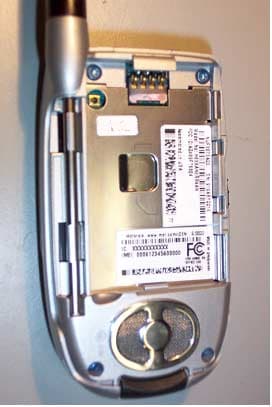
Click to zoom
Application Details
- Equipment Class
- TNE - Licensed Non-Broadcast Transmitter Held to Ear
- Date of Grant
- Jul 16, 2003
- Application Purpose
- Original Equipment
- Date of Application
- Jun 26, 2003
- Equipment Note
- i730
- Frequency Range
- 896.00000000 - 901.00000000
- Company
- Motorola Solutions, Inc.
- Country
- United States
Documents & Files
Document Text
Text extracted from the exhibit documents filed with the FCC. Open a document above to read the original.
Users Manual
Motorola iDEN Digital Multi-service Data-capable Phone i 730 Phone User’s Guide THIRD DRAFT @NNTN4760A@NNTN4760A i ContentsGetting Started .............................................. 1 Locating Your SIM Card....................................... 3Battery.................................................................. 3Activating Service ................................................ 6Powering On ........................................................ 6Enabling Over-the-Air Security ............................ 7Finding Your Phone Number ............................... 7Completing Setup ................................................ 8Phone Basics ....................................................... 8SIM Card Security.............................................. 12Locking the Keypad ........................................... 15Accessories........................................................ 15For More Information ......................................... 15 Making Calls ................................................ 17 Receiving Calls .................................................. 17Call Icons ........................................................... 18Entering the Number to Call............................... 18Missed Phone Calls ........................................... 21Using Speakerphone ......................................... 21Using Mute ......................................................... 22 Making Emergency Phone Calls ........................ 22 Call Alerts .................................................... 23 Sending Call Alerts............................................. 23Receiving Call Alerts .......................................... 23Using the Call Alert Queue................................. 23 Recent Calls ................................................ 25 Storing Recent Calls to Contacts ....................... 25Deleting Recent Calls......................................... 26 Contacts ...................................................... 27 Viewing Contacts ............................................... 28Creating Entries ................................................. 29Storing Numbers Faster ..................................... 30Editing Entries .................................................... 31Deleting Entries.................................................. 31Checking Capacity ............................................. 31Creating Pauses and Waits................................ 31International Numbers........................................ 32Accessing Contacts with GSM Phones.............. 32 Call Forwarding........................................... 33 Forwarding All Calls ........................................... 33Turning Off Call Forwarding ............................... 33 ii Forwarding Missed Calls.................................... 34 Ring Tones................................................... 35 Using the Vibrate Feature .................................. 35Turning Ring Tones Off...................................... 35Ring and Vibrate ................................................ 36Assigning Ring Tones to Contacts..................... 36Viewing Ring Tone Assignments ....................... 37Downloading More Ring Tones.......................... 37Managing Memory ............................................. 37Deleting Custom Ring Tones............................. 37 Messages ..................................................... 39 Message Notifications........................................ 39Voice Mail .......................................................... 39Text and Numeric Messages ............................. 40Net Alerts ........................................................... 41 Mobile Originated Text Messaging ............ 43 Setting Up .......................................................... 43Receiving Messages.......................................... 43Reading Messages From the Message Center . 44Creating and Sending Messages....................... 44Managing Memory ............................................. 47 Datebook ..................................................... 49 Viewing Datebook .............................................. 49Creating Events.................................................. 50Editing Events .................................................... 52Deleting Events .................................................. 52Receiving Reminders ......................................... 53Making Calls From Datebook............................. 53Customizing Datebook Setup............................. 54 Java Applications ....................................... 55 Running Applications ......................................... 55Suspending Applications.................................... 55Resuming Applications....................................... 55Ending Applications............................................ 56Downloading Applications .................................. 56Installing Applications......................................... 56Deleting Applications.......................................... 56Managing Memory ............................................. 57Shortcuts on the Main Menu .............................. 57Java Applications and GPS Enabled ................. 58 GPS Enabled ............................................... 61 IMPORTANT: Things to Keep in Mind ............... 61 iii Making an Emergency Call ................................ 62Viewing Your Approximate Location .................. 63Enhancing GPS Performance............................ 64Updating Satellite Almanac Data ....................... 65Setting Privacy Options...................................... 66Using GPS with Map Software........................... 67 Voice Records ............................................. 69 Creating Voice Records..................................... 69Playing Voice Records....................................... 69Labelling Voice Record…
Text truncated - open the document above for the full version.
Cover Letter(s)
______________________________________________________________________________ 8000 West Sunrise Boulevard, Fort Lauderdale, Florida 33322. Confidentiality Request Date: 20 th June 2003 Authorization & Evaluation Division Federal Communications Commission Laboratory 7435 Oakland Mills Road Columbia, MD 21046 Subject: Application for Certification of Transmitter with FCC ID: AZ489FT5824. Dear Sir or Madam: Motorola is requesting that Exhibit 4 (Circuit Descriptions), Exhibit 5 (Schematic Diagrams), Exhibit 10 (Parts List and Tune Up Procedures), and Exhibit 12 (Operational Description) not be made routinely available for public inspection. Motorola considers the information in these exhibits to be classified as trade secrets, pursuant to 47 CFR Section 0.457(d) and Section 552(b)(4) of the Freedom of Information Act. Please mark Exhibits 4, 5, 10, and 12 as “Confidential.” Please contact me if you require any additional information. Sincerely, /s/ Mike Ramnath FCC Liaison Tel: (954) 723-5793 E-mail: [email protected] EXHIBIT 13b
External Photos
FCC Filing Package for Motorola i730 Transceiver FCC ID: AZ489FT5824 IDEN, Motorola Inc., 8000 W. Sunrise Blvd., Plantation, FL 33322, USA WWW.MOT.COM/iDEN Page: 3 - 1 Exhibit 3. External Photographs -- Pursuant to 47 CFR 2.1033(c)12 The radio product shapes, colors and housing/bezel vary. Photograph 3-1: Front view, antenna retracted. Photograph 3-2: Back view, antenna retracted, battery cover attached. FCC Filing Package for Motorola i730 Transceiver FCC ID: AZ489FT5824 IDEN, Motorola Inc., 8000 W. Sunrise Blvd., Plantation, FL 33322, USA WWW.MOT.COM/iDEN Page: 3 - 2 Photograph 3-3: Button side view, antenna retracted, battery cover attached. Photograph 3-4: Antenna side view, antenna extended, battery cover attached. FCC Filing Package for Motorola i730 Transceiver FCC ID: AZ489FT5824 IDEN, Motorola Inc., 8000 W. Sunrise Blvd., Plantation, FL 33322, USA WWW.MOT.COM/iDEN Page: 3 - 3 Photograph 3-5: Back view, antenna retracted, battery cover attached. FCC Filing Package for Motorola i730 Transceiver FCC ID: AZ489FT5824 IDEN, Motorola Inc., 8000 W. Sunrise Blvd., Plantation, FL 33322, USA WWW.MOT.COM/iDEN Page: 3 - 4 Photograph 3-6: Back view, battery cover removed.
ID Label/Location Info
FCC Filing Package for Motorola i730Transceiver FCC ID: AZ489FT5824 IDEN, Motorola Inc., 8000 W. Sunrise Blvd., Plantation, FL 33322, USA WWW.MOT.COM/iDEN Page 1-2 Exhibit 1. Identification Label -- Pursuant to 47 CFR 2.925, 2.1065 and 2.1033(c)11 1.1 Location Back side of the radio product unit chassis (Photograph 1.1). 1.2 Type The label is a white polyester film laminate with a pressure sensitive adhesive backing. The adhesive is a permanent type acrylic with minimum peel strength of 5 lbs/in. 1.3 Markings (Text) Enlarged view of label (showing FCC ID and manufacturer type number): Photograph 1.1: Location of label on back of unit’s housing (battery cover removed). Photograph 1.2: Zoom view of labels containing FCC ID and FCC Logo FCC Filing Package for Motorola i730Transceiver FCC ID: AZ489FT5824 IDEN, Motorola Inc., 8000 W. Sunrise Blvd., Plantation, FL 33322, USA WWW.MOT.COM/iDEN Page 1-2 Exhibit 1A. General Information 1A.1 Production Plans Quantity production is planned. 1A.2 Application References -- Pursuant to 47 CFR 2.948 and 2.1061 Reference is made to the following Motorola "Application References" 1. Open Area Test Site “OATS” (FCC Registration: 91932 / Industry of Canada: IC3679) 1A.3 Data Submittal Procedure Data located in Exhibit 6 is supplied in accordance with 47CFR2, Sub-part J and Part 90, Sub-parts I and Sub-part S of the Commission’s rules. 1A.4 Similar, currently Certified Transceiver FCC ID: AZ489FT5822 1A.5 Additional Considerations This radio product also integrates a receiver that will receive and process signals from Global Positioning System satellites. The radio product can also function as a Part 15.3(r) computer peripheral device when functioning as an RF modem when connected to a computer via a data cable accessory (Exhibit 12). A Declaration of Conformity in accordance with 47CFR2.1077(a) is provided in Exhibit 8 as evidence of compliance with Part 15 requirements for these additional Class B digital device functionalities per 47CFR15.101(a). Compliance with Part 15 requirements for the Direct-Conversion (zero IF superheterodyne) receiver has been determined by verification in accordance with 47CFR15.1.
Internal Photos
FCC Filing Package for Motorola i730 Transceiver FCC ID: AZ489FT5824 IDEN, Motorola Inc., 8000 W. Sunrise Blvd., Plantation, FL 33322, USA WWW.MOT.COM/iDEN Page: 9- 1 Exhibit 9. Internal Photographs -- Pursuant to 47 CFR 2.1033(c)12 Photograph 9-1: Front side view of radio PCB. Photograph 9-2: Back side view of radio PCB. Photograph 9.5: Back side view of keyboard. Photograph 9-3: Front side view of radio PCB without shields. Photograph 9-4: Back side view of radio PCB without shields. Photograph 9.6: Front side view of keyboard.
RF Exposure Info
FCC Package for Motorola i730 Transceiver FCC ID: AZ489FT5824 IDEN, Motorola Inc., 8000 W. Sunrise Blvd., Plantation, FL 33322, USA WWW.MOT.COM/iDEN Page: 7 - 1 Exhibit 7. Measurement Procedures -- 47 CFR. 2.947 This exhibit presents a summary of how the measurements were made. 7.1 RF Power -- Pursuant to 47 CFR 2.947(c) Method of Conducted Output Power Measurement : Adaptation of TIA/EIA-603-B clause 2.2.1 for Pulsed Measurements The RF output power is not adjustable by the user. The output power is controlled by the radio in response to the received signal strength or by or special radio service software. To obtain RF output power reading, the radio was programmed to utilize the maximum and minimum output power setting. To correct the average reading power meter, a setting of the duty cycle on the RF power meter was set to 16.667% for herein reported 6:1 TDM test signals. A special DC/RF test fixture was utilized to interface with the radio test RF connector while simultaneously supplying the nominal operating voltage of 4.0V. The radio RF connector is utilized in all factory tuning and testing procedures, and provides a 50 ohm connection to the transmitter path while disconnecting the radio antenna. All conducted measurements were performed via this test port. NOTE: This DC/RF test fixture in not offered for sale. Method of Measurement for Effective Radiated Power: TIA/EIA-603-B 2.2.17.2 The ERP characteristic was measured while a radio was set to transmit a test mode CW signal at the maximum rated output power (+/- 5%) and was vertically mounted on a non-conducting platform/turntable in a RF Anechoic Chamber. The power received at an antenna located at the end of the chamber was recorded on a spectrum analyzer for a complete 360-degree rotation. The same procedure was repeated for 800 and 900 MHz sleeve reference dipole. The CW RF output power of the radio product was measured by a conducted means to determine the necessary input power for the reference dipole (after compensation for interface, cable, and antenna losses). The maximum power levels measured were compared to determine the antenna gain of the radio antenna in reference to the standard dipole. This relative antenna gain was used to scale the maximum RF conducted output power and determine the maximum herein reported ERP. 7.2 Emission Mask-- Pursuant to 47 CFR 2.947(b) Method of Measurement: Per TIA/EIA-603-B clause 2.2.11 (1) Set the radio for measurement of RF output power using the power test procedure in the service manual which employs a pseudo random data sequence per part 2.1049(h), and attach it to a spectrum analyzer through a 10 dB attenuator. The analyzer is to be set for peak detection with a video bandwidth of 3 times the resolution bandwidth setting, a span of 100 kHz, and a sweep period of 20 seconds. (2) Using a 30 kHz resolution bandwidth to assure that essentially all of the transmitted FCC Package for Motorola i730 Transceiver FCC ID: AZ489FT5824 IDEN, Motorola Inc., 8000 W. Sunrise Blvd., Plantation, FL 33322, USA WWW.MOT.COM/iDEN Page: 7 - 3 energy is measured, obtain a “rainbow” curve and adjust the analyzer setting so that the crest of the curve lies at the 0 dB reference location. This is portrayed as trace 1 on the analyzer display. (3) Reduce the resolution bandwidth to 300 Hz to characterize the transmitter emission on- channel and adjacent channels spectral performance characteristic. This is portrayed as trace 2 on the analyzer display of Figures 6-7 to 6-12. (4) Overlay the applicable emission mask on the analyzer display as trace 3. (5) Compare traces 2 and 3 to ensure that trace 2 never exceeds trace 3. 7.3 Radiated Spurious Emissions -- Pursuant to 47 CFR 2.947(b) Test Sites: Open Area Test Site (OATS) of the Timco Eng. Lab, 849 N.W. State Road 45, Newberry, Florida 32669 which is accredited to ISO/IEC 25 from the American Association for Laboratory Accreditation (FCC Registration: 95517 /Industury Canada: 2056-A).. The radiated emission testing was performed for minimum and maximum power levels in transmit mode. Method of Measurement: TIA/EIA-603-B clause 2.2.12 The equipment is placed on the turntable and placed in normal operation transmit mode of operation. A broad-band receiving antenna located 3 meters from the transmitter receives any signal radiated from the transmitter and its operational accessories. The antenna is adjustable in height and can be rotated for horizontal or vertical polarization. A spectrum analyzer covering the necessary frequency range is used to detect and measure any radiation received by the antenna. The transmitter’s modulated pseudo random digital signal is monitored and adjusted to obtain peak reading of received signals wherever they occur in the spectrum by: (1) Rotating the transmitter under test. (2) Adjusting the antenna height. The testing procedure is repeated for both horizontal and vertical polarization of the receiving antenna. Relative signal strength is indicated on the spectrum analyzer connected to this antenna. The spectrum analyzer resolution bandwidth was set to 10 kHz for emissions below 1 GHz, and 1 MHz for higher frequency emissions. To obtain actual radiated signal strength for each spurious and harmonic frequency observed, a standard signal generator with calibrated output is connected to an antenna adjusted to in the range from 30 MHz to that harmonic frequency. This antenna is substituted for the transmitter under test. The signal generator output level is adjusted until a reading identical to that obtained with the actual transmitter is observed on the spectrum analyzer. Signal strength is then derived from the generator and appropriate cable losses due to set up. Measured emissions for both maximum and minimum transmit power levels are recorded in tables in Exhibit 6. FCC Package for Motorola i730 Transceiver FCC ID: AZ489FT5824 IDEN, Motorola Inc., 8000 W. Sunrise Blvd., Plantation, FL 33322, USA WWW.MOT.COM/iDEN Page: 7 - 4 7.4 Fr…
Text truncated - open the document above for the full version.
Test Report
Form-SAR-Rpt-Rev. 2.00 Page 1 of 27 CGISS EME Test Laboratory 8000 West Sunrise Blvd Fort Lauderdale, FL. 33322 S.A.R. EME Compliance Test Report Part 1 of 2 Note: Based on the information and the testing results provided herein, the undersigned certifies that when used as stated in the operating instructions supplied, said product complies with the national and international reference standards and guidelines listed in section 2.0 of this report. Signature on file 6/19/03 ____________________________________________________________ _________________________ Ken Enger Date Approved Senior Resource Manager, Laboratory Director, CGISS EME Lab Note: This report shall not be reproduced without written approval from an officially designated representative of the Motorola EME Laboratory. Date of Report: June 19, 2003 Report Revision: Rev. 0 Manufacturer: Motorola Product Description: 1:6, 2:6, 81:120 TDM; 64 QAM, 16 QAM & QPSK Modulation; 0.6 W Pulse average FCC ID: AZ489FT5824 Device Model: H63XAN6RR4AN Certificate Number: 1449-02 Test Period: 5/23/03-6/17/03 EME Tech: Clint Miller/Ed Church EME Eng.: Stephen Whalen (Sr. EME Eng.) Author: Michael Sailsman Global EME Regulatory Affairs Liaison Form-SAR-Rpt-Rev. 2.00 Page 2 of 27 TABLE OF CONTENTS Part 1 of 2 1.0 Introduction 2.0 Reference Standards and Guidelines 3.0 Description of Test Sample 3.1 Test Signal 3.2 Test Output Power 4.0 Description of Test Equipment 4.1 Description of S.A.R Measurement System 4.2 Description of Phantom 4.2.1 Flat Phantom 4.2.2 SAM phantom 4.3 Simulated Tissue Properties 4.3.1 Type of Simulated Tissue 4.3.2 Simulated Tissue Composition 4.4 Test condition 5.0 Description of Test Procedure 5.1 Device Test Positions 5.1.1 Abdomen 5.1.2 Head 5.1.3 Face 5.2 Test Position Photographs 5.3 Probe Scan Procedures 6.0 Measurement Uncertainty 7.0 S.A.R. Test Results 7.1 S.A.R. results 7.2 Peak S.A.R. location 7.3 Highest S.A.R. results calculation methodology 8.0 Conclusion Part 2 of 2 Appendix A: Power Slump Data/Shortened scan Appendix B: Data Results Appendix C: Dipole System Performance Check Results Appendix D: Calibration Certificates Appendix E: Illustration of Body-worn Accessories Appendix F: Accessories and options test status and separation distances Form-SAR-Rpt-Rev. 2.00 Page 3 of 27 REVISION HISTORY Date Revision Comments 6/19/03 O Prototype results Form-SAR-Rpt-Rev. 2.00 Page 4 of 27 1.0 Introduction This report details the utilization, test setup, test equipment, and test results of the Specific Absorption Rate (S.A.R.) measurements performed at the CGISS EME Test Lab for model number H63XAN6RR4AN, FCC ID: AZ489FT5824. The applicable exposure environment is General Population/Uncontrolled. The test results included herein represent the highest S.A.R. levels applicable to this product and clearly demonstrate compliance with FCC General Population/Uncontrolled RF Exposure limits of 1.6 mW/g per the requirements of 47 CFR 2.1093(d). 2.0 Reference Standards and Guidelines This product is designed to comply with the following national and international standards and guidelines. • United States Federal Communications Commission, Code of Federal Regulations; 47CFR part 2 sub-part J • American National Standards Institute (ANSI) / Institute of Electrical and Electronic Engineers (IEEE) C95. 1-1992 • Institute of Electrical and Electronic Engineers (IEEE) C95.1-1999 Edition • International Commission on Non-Ionizing Radiation Protection (ICNIRP) 1998 • Ministry of Health (Canada) Safety Code 6. Limits of Human Exposure to Terminal frequency Electromagnetic Fields in the Frequency Range from 3 kHz to 300 GHz, 1999 • Australian Communications Authority Terminal communications (Electromagnetic Radiation - Human Exposure) Standard 2001 • ANATEL, Brazil Regulatory Authority, Resolution 256 (April 11, 2001) "additional requirements for SMR, cellular and PCS product certification." Form-SAR-Rpt-Rev. 2.00 Page 5 of 27 3.0 Description of Test Sample FCC ID: AZ489FT5824 is a digital multi-service data capable device that employs time division multiplexing transmission technology with a duty cycle ranging from 16.67% to 33.33% using 16-QAM modulation for voice or circuit data transmission. There is a Split 3:1 mode that operates using a 16.67% transmission duty cycle. Two 7.5ms pulses occurs during the six time slots within the 90-msec frame format. This mode is available in both the 806-825MHz and 896-902MHz bands in the telephone interconnect mode only. Packet data transmission is also supported up to a maximum duty cycle of 67.5% using quad QPSK modulation. This device will be marketed to and used by the general population. This device may be used while held against the head in voice mode, in front of the face in PTT mode, and against the body in both voice and data modes. FCC ID: AZ489FT5824 is capable of operating in the 806-825 MHz and 896-902MHz bands. Packet data transmission is not available while transmitting in the 896-902 MHz band. The rated power is 0.6 watts pulsed averaged. The maximum output is 0.7 watts pulsed average as defined by the upper limit of the production line final test station. Form-SAR-Rpt-Rev. 2.00 Page 6 of 27 FCC ID: AZ489FT5824 is offered with the following options and accessories: Antenna 8585924E01 Retractable whip ¼ wave antenna; 806-941 MHz; -1.30dBd @ 813MHz (extended) to 0.10dBd @ 896MHz (retracted) Batteries SNN5705B 750 mAh Lithium Ion SNN5704A 600 mAh Lithium Ion Body-worn Accessories NNTN4682A Holster Applicable attachments SYN0547A Digital Camera NTN8496A Light-weight headset w/ mic SYN7875C Hearing Aid Neck loop (incl. SYN8608C, SNN5536A battery) SYN8390B Privacy Earpiece and Microphone NNTN4033A Privacy earpiece and Mic w/ PTT NSN6066A Remote speaker w/PTT NNTN4877A Mini Keyboard SYN8146C Lightweight Over the Ear headset w/ boom microphone NTN8513B Lightweight headband NNTN4620A Silver Ear Bud NKN6544B RS232 Data cable NKN6540A Dual Port Adaptor cable NNTN4007A USB Data cable NNTN40…
Text truncated - open the document above for the full version.
Test Report
Form-SAR-Rpt-Rev. 2.00 Page 1 of 62 CGISS EME Test Laboratory 8000 West Sunrise Blvd Fort Lauderdale, FL. 33322 S.A.R. EME Compliance Test Report Part 2 of 2 Note: Based on the information and the testing results provided herein, the undersigned certifies that when used as stated in the operating instructions supplied, said product complies with the national and international reference standards and guidelines listed in section 2.0 of this report. Signature on file 6/19/03 ____________________________________________________________ _________________________ Ken Enger Date Approved Senior Resource Manager, Laboratory Director, CGISS EME Lab Note: This report shall not be reproduced without written approval from an officially designated representative of the Motorola EME Laboratory. Certificate Number: 1449-02 Date of Report: June 19, 2003 Report Revision: Rev. 0 Manufacturer: Motorola Product Description: 1:6, 2:6, 81:120 TDM; 64 QAM, 16 QAM & QPSK Modulation; 0.6 W Pulse average FCC ID: AZ489FT5824 Device Model: H63XAN6RR4AN Test Period: 5/23/03-6/17/03 EME Tech: Clint Miller/Ed Church EME Eng.: Stephen Whalen (Sr. EME Eng.) Author: Michael Sailsman Global EME Regulatory Affairs Liaison Form-SAR-Rpt-Rev. 2.00 Page 2 of 62 APPENDIX A Power Slump Data/Shortened Scan Form-SAR-Rpt-Rev. 2.00 Page 3 of 62 DUT Power versus time data Form-SAR-Rpt-Rev. 2.00 Page 4 of 62 Shortened Scan Results FCC ID: AZ489FT5824; Test Date: 6/10/03 Motorola CGISS EME Laboratory Run #: Lear-R1-030610-04 Model #: H63XAN6RR4AN SN: 364ADJ0002 TX Freq: 813.5125 MHz Sim Tissue Temp: 21.3 (Celsius) Start Power: .714 W Normal scan (29min) Start Power: .716 W Short scan (6min) Antenna: IN Battery Kit: SNN5704A Carry Accessories: None Attached Accessories: None This shortened scan reflects the highest S.A.R. producing configuration; Run time 6 minutes. Representative “normal” scan run time was 29 minutes “Shortened” scan max calculated S.A.R. using S.A.R. drift: 1-g Avg. = 0.94 mW/g; 10-g Avg. = 0.62mW/g “Normal” scan max calculated S.A.R. using S.A.R. drift: 1-g Avg. = 1.19 mW/g; 10-g Avg. = 0.76 mW/g (see section 7.1 run # SW-LEar-R1-030610-04) DUT in Cheek touch position against the phantom SAM Phantom; Left Hand Section; Position: (90°,59°); Probe: ET3DV6 - SN1384(Cal Date 05-15-2003); ConvF(6.60,6.60,6.60); Probe cal date: 15/05/03; Crest factor: 3.0; IEEE Head 813 MHz: σ = 0.93 mho/m εr = 43.5 ρ = 1.00 g/cm3; DAE3: 363V1 DAE Cal Date: 05/13/2003 Cube 7x7x7: SAR (1g): 0.919 mW/g, SAR (10g): 0.601 mW/g * Max outside, (Worst-case extrapolation) Coarse: Dx = 15.0, Dy = 15.0, Dz = 10.0; Max at 37.5, 19.5, 4.7 Power drift: -0.10 dB Form-SAR-Rpt-Rev. 2.00 Page 5 of 62 FCC ID: AZ489FT5824; Test Date: 6/10/03 Motorola CGISS EME Laboratory Run #: Ab-R1-030608-04 Model #: H63XAN6RR4AN SN: 364ADJ0002 TX Freq: 824.9875 MHz Sim Tissue Temp: 21.1 (Celsius) Start Power: .639 W Normal scan (27min) Start Power: .630 W Short scan (8min) Antenna: in Battery Kit: SNN5705B Carry Accessories: Belt Clip #: NNTN4682A Attached Accessory: None This shortened scan reflects the highest S.A.R. producing configuration; Run time 8 minutes. Representative “normal” scan run time was 29 minutes “Shortened” scan max calculated S.A.R. using S.A.R. drift: 1-g Avg. = 1.05 mW/g; 10-g Avg. = 0.75 mW/g “Normal” scan max calculated S.A.R. using S.A.R. drift: 1-g Avg. = 1.15 mW/g; 10-g Avg. = 0.81 mW/g (see section 7.1 run # CM-Ab-R1-030604-16) DUT w/ carry case against phantom Flat Phantom; Device Section; Position: (90°,90°); Probe: ET3DV6 - SN1384(Cal Date 05-15-2003); ConvF (6.50,6.50,6.50); Probe cal date: 15/05/03; Crest factor: 1.5; FCC Body_813 MHz: σ = 0.94 mho/m εr = 53.3 ρ = 1.00 g/cm3; DAE3: 363V1 DAE Cal Date: 05/13/2003 Cube 5x5x7: SAR (1g): 0.946 mW/g, SAR (10g): 0.672 mW/g, (Worst-case extrapolation) Coarse: Dx = 15.0, Dy = 15.0, Dz = 10.0; Max at 33.0, 70.5, 4.7 Power drift: 0.05dB Form-SAR-Rpt-Rev. 2.00 Page 6 of 62 APPENDIX B Data Results Form-SAR-Rpt-Rev. 2.00 Page 7 of 62 FCC ID: AZ489FT5824; Test Date: 6/10/03 Motorola CGISS EME Laboratory Run #: Lear-R1-030610-04 Model #: H63XAN6RR4AN SN: 364ADJ0002 TX Freq: 813.5125 MHz Sim Tissue Temp: 21.1 (Celsius) Start Power: .714 W Antenna: IN Battery Kit: SNN5704A Carry Accessories: NONE Attached Accessory: NONE DUT in cheek touch position against the phantom SAM Phantom; Left Hand Section; Position: (90°,59°); Probe: ET3DV6 - SN1384(Cal Date 05-15-2003); ConvF(6.60,6.60,6.60); Probe cal date: 15/05/03; Crest factor: 3.0; IEEE Head 813 MHz: σ = 0.93 mho/m εr = 43.5 ρ = 1.00 g/cm3; DAE3: 363V1 DAE Cal Date: 05/13/2003 Cube 7x7x7: SAR (1g): 0.955 mW/g, SAR (10g): 0.613 mW/g * Max outside, (Worst-case extrapolation) Coarse: Dx = 15.0, Dy = 15.0, Dz = 10.0; Max at 37.5, 19.5, 4.7 Power drift: -0.94dB Note: “Max outside” has been identified by SPEAG as an unresolved intermittent occurrence with the DASY 3 application even when the entire peak area is captured. Form-SAR-Rpt-Rev. 2.00 Page 8 of 62 FCC ID: AZ489FT5824; Test Date: 5/27/03 Motorola CGISS EME Laboratory Run #: LEAR-R1-030527-08 Model #: H63XAN6RR4AN SN: 364ADJ0002 TX Freq: 806.0125 MHz Sim Tissue Temp: 21.1 (Celsius) Start Power: .688 W Test time: 29 min. Antenna: out Battery Kit: SNN5704A Carry Accessories: NONE Attached Accessory: NONE DUT in cheek touch position against the phantom SAM Phantom; Left Hand Section; Position: (90°,59°); Probe: ET3DV6 - SN1384(Cal Date 05-15-2003); ConvF (6.60,6.60,6.60); Probe cal date: 15/05/03; Crest factor: 3.0; IEEE Head_813 MHz: σ = 0.93 mho/m εr = 43.4 ρ = 1.00 g/cm3; DAE3: 363V1 DAE Cal Date: 05/13/2003 Cube 7x7x7: SAR (1g): 0.789 mW/g, SAR (10g): 0.536 mW/g, (Worst-case extrapolation) Coarse: Dx = 15.0, Dy = 15.0, Dz = 10.0; Max at 36.0, 15.0, 4.7 Power drift: -0.46dB Form-SAR-Rpt-Rev. 2.00 Page 9 of 62 FCC ID: AZ489FT5824; Test Date: 5/27/03 Motorola CGISS EME Laboratory Run #: REAR-R1-030527-12 Model #: H63XAN6RR4AN SN: 364ADJ0002 TX Freq: 813.5125 MHz Sim Tissue Temp: 21.2 (Celsius) Start Power:…
Text truncated - open the document above for the full version.
Test Report
FCC Filing Package for Motorola i730 Transceiver FCC ID: AZ489FT5824 IDEN, Motorola Inc., 8000 W. Sunrise Blvd., Plantation, FL 33322, USA WWW.MOT.COM/iDEN Page: 6- 1 Exhibit 6. Measured Data -- Pursuant 47 CFR. 2.1041 6.1 Transmitter Power The transmitter is a variable power type used in a SMR trunking system. Output power (as defined in 47 CFR 90.7) is dynamically controlled as described in Exhibit 12. 6.1.1 Maximum Output Power Rating -- Pursuant 47 CFR 2.1033(c)7 and 90.635(d)) Maximum output power rating: 700 milliwatts (28.45 dBm), pulse average power Note 1: Nominal output power rating: 600 milliwatts (27.78 dBm) (Pulse average power). Note 2: These ratings are compliant with the FCC maximum of 100 watts (50 dBm) for Mobile stations Note 3: The term pulse average power is used to specify the power that would be measured during the intervals of recurrent TDM transmission pulses by an average responding RF power meter. Power expressed in this manner is independent of the TDM duty cycle, and facilitates RF system coverage analysis. …
Text truncated - open the document above for the full version.
Contact Information
Applicant
Deanna Zakharia(Regulatory Compliance Manager)
Test Firm
MotorolaWilliam Elliott
Technical Specifications
| # | Rule Parts | Frequency Range | Power Output | Emission | Tolerance |
|---|---|---|---|---|---|
| 2 | 9 | 896 MHz - 901 MHz | 700.00 mW | 18K3D7W | 0.5 ppm |
Other Applications from Motorola Solutions, Inc.

AZ489FT4980
Sep 08, 2026Portable two way radio
Equipment Class
TNF - Licensed Non-Broadcast Transmitter Held to FaceAZ489FT4981
Aug 14, 2026Handheld Portable - TANAPA BPR 45 400-470 MHZ 4W NKP
Equipment Class
TNF - Licensed Non-Broadcast Transmitter Held to Face
AZ489FT7187
Jul 13, 2026Portable 2-Way Radio with Bluetooth, Bluetooth LE, WIFI 2.4GHz, WIFI 5GHz, LTE
Equipment Class
DSS - Part 15 Spread Spectrum TransmitterAZ499FT6031
May 11, 2026Operation Critical Wireless Earpiece PTT
Equipment Class
DSS - Part 15 Spread Spectrum Transmitter
AZ499FT5879
Dec 19, 20252-way Portable Radio with BT, BTLE, WIFI, NFC and LTE
Equipment Class
DSS - Part 15 Spread Spectrum Transmitter