AZ489FT5830iDEN i325 with MOTOtalk
Motorola Solutions, Inc.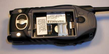
Click to zoom
Application Details
- Equipment Class
- TNE - Licensed Non-Broadcast Transmitter Held to Ear
- Date of Grant
- Apr 27, 2004
- Application Purpose
- Original Equipment
- Date of Application
- Feb 26, 2004
- Equipment Note
- iDEN i325 with MOTOtalk
- Frequency Range
- 896.00000000 - 902.00000000
- Company
- Motorola Solutions, Inc.
- Country
- United States
Documents & Files
Document Text
Text extracted from the exhibit documents filed with the FCC. Open a document above to read the original.
Users Manual
Motorola iDEN Digital Multi-service Data-capable Phone i 325 Phone User’s Guide SECOND DRAFT @NNTN5506A@NNTN5506A IMPORTANT NOTICE: PLEASE READ PRIOR TO USING YOUR PHONEThe SIM card provided in this kit is intended for use with the phone provided in this package. Loss of certain features will result when using a SIM card from one of the following models: i 30 sx , i 35 s , i 50 sx , i 55 sr , i 58 sx , i 60 c , i 80 s , i 85 s , i 88 s , i 90 c , i 95 cl series, and the i 2000 series. For more information on SIM card compatibility, go to www.motorola.com/iden/support. i ContentsGetting Started........................................... 1 Locating Your SIM Card ....................................2Activating Service ..............................................5Powering On and Off.........................................5Enabling Over-the-Air Security..........................6Finding Your Phone Number.............................6Phone Basics ....................................................7SIM Card Security ...........................................11Locking the Keypad .........................................14Accessories .....................................................15For More Information .......................................15 Making Calls ............................................. 16 Phone Calls .....................................................16Private Calls ....................................................16Receiving Calls................................................16Call Icons.........................................................17Ways to Enter Calls.........................................17Using Speakerphone .......................................19Using Mute ......................................................20 Making Emergency Phone Calls .....................20 Call Alerts..................................................21 Sending Call Alerts..........................................21Receiving Call Alerts .......................................21Using the Call Alert Queue..............................21 Recent Calls ..............................................23 Storing Recent Calls to Contacts ....................23Deleting Recent Calls......................................24 Contacts ....................................................25 Viewing Contacts ............................................26Creating Entries ..............................................27Storing Numbers Faster ..................................28Editing Entries .................................................29Deleting Entries ...............................................29Checking Capacity ..........................................30Creating Pauses and Waits.............................30International Numbers .....................................30Accessing Contacts with GSM Phones ...........31 Call Forwarding ........................................32 Forwarding All Calls ........................................32 ii Turning Off Call Forwarding ............................33Forwarding Missed Calls .................................33Viewing Call Forwarding Settings....................34 Additional Calling Options...................... 35 Call Waiting .....................................................35Call Hold ..........................................................363-Way Calling ..................................................36Creating Pauses and Waits While Dialing.......37Making International Calls ...............................37Setting One Touch PTT...................................37Group Calls .....................................................38Call Timers ......................................................39Using Your Phone as a Modem ......................40Making TTY Calls ............................................41 Memo ........................................................ 43Ring Tones ............................................... 44 Setting Your Phone to Vibrate .........................44Turning Ring Tones Off ...................................44Ring and Vibrate..............................................45Assigning Ring Tones to Contacts ..................45 Viewing Ring Tone Assignments ....................46Downloading More Ring Tones .......................46Managing Memory ..........................................46Deleting Custom Ring Tones ..........................47 Entering Text ............................................48 Using Alpha Mode ...........................................48Using Word Mode ...........................................48Special Function Keys.....................................49Using Numeric Mode.......................................50Using Symbols Mode ......................................50 Advanced Features ..................................51 Making Talkgroup or Hub Calls .......................51Emergency Group Call ....................................52Isolated Site Operation (ISO) ..........................55Status Messages.............................................55 Your Messaging Services ........................57 Voice Mail........................................................57Text Messages ................................................57 Receiving Messages ................................59 Message Notifications .....................................59 iii Message Center ..............................................60 Voice Mail Messages ............................... 61 Receiving a Message ......................................61Accessing Voice Mail from the Message Center ...................................61 Sending Unanswered Calls to Voice Mail .......61 MOSMS Messages ................................... 62 Setting Up........................................................62Receiving a Message ......................................62Reading from the Message Center .................63Creating and Sending Messages ....................63Managing Memor…
Text truncated - open the document above for the full version.
Users Manual
23 MOTOtalkThe MOTOtalk feature allows direct two-way phone-to-phone communications between two or more phones equipped for MOTOtalk. MOTOtalk does not require any network connection; therefore, you can make and receive MOTOtalk calls in places where not network service is available. You can talk to anyone on your code and channel within your range.MOTOtalk allows you to:• use code or private mode operation • use up to 10 channels • communicate with standalone MOTOtalk radiosNote: MOTOtalk is a new digital service and is not compatible with older Family Radio Services products such as Talkabout radios. Using MOTOtalkWhile using MOTOtalk, the idle screen will look similar to the on-network idle screen (see “Phone Basics” on page 7). The MOTOtalk icon on the display indicates that you are in MOTOtalk mode. The tone emitted from your phone when using MOTOtalk will have 4 beeps and will be longer than the standard tone heard with on-network Private and Group calls.While using MOTOtalk, it will not be possible to communicate, transmit or receive data from the network. Activating MOTOtalk1 Scroll to MOTOtalk on the main menu. 2 Select Go to MOTOtalk , you’ll see on the display: Switching to MOTOtalk please wait . You’ll be on MOTOtalk screen. Mesg Contcs s d 1 S 24 MOTOtalkSetup OptionsThe Setup Option allows you to setup options for MOTOtalk:1 From the main menu, select MOTOtalk Options . 2 Select Setup . 3 Scroll to Direct Launch or State Tone . 4 Press A . • Direct Launch — When you select MOTOtalk from the Main Menu and Direct Launch is ON, your phone launches directly to MOTOtalk. Otherwise, it displays an screen allowing you to change the MOTOtalk Options. • State Tone — A tone will remind you periodically that you are in MOTOtalk. Your phone cannot receive incoming calls from the network while in MOTOtalk.+ MOTOtalk Icons MOTOtalk Options (intermediate screen):-Go To MOTOtalk (launch MOTOtalk)-Setup-HelpMOTOtalk Type-Code-ChannelMOTOtalk In UseNo Signal - Indicates you are off-network and in MOTOtalk mode. 25 MOTOtalk Code Calls MOTOtalk Code CallsSetting Channels and CodesChannelsYour phone has 10 channels and 15 codes. To have a conversation, all parties must be on the same channel and code.To set a channel:1 From the idle screen, press A under Edit . 2 Select Channel . 3 Press A . 4 Scroll to the Channel you want to select. 5 Press A . CodesTo set a code:1 From the idle screen, press A under Edit . 2 Select Code . 3 Press A . 4 Scroll to the Code you want to select. 5 Press A . Note: All parties that are on your code and channel can hear your conversation. Receive All1 You can set your phone with Code set to Receive All . Your phone will receive calls from any phone that has been set to the same Channel regardless of the Code (1-15). 2 If you receive a call while in Receive All , your phone display will change from Receive All to the Code on which the transmission was received.Note: You cannot initiate a call when the code is set to Receive All . If you press the PTT button when in Receive All it will ask you to enter a code. Contcs d S MT Ready Code:Receive All Channel:4 Edit status icons text area menu icondisplay options 26 MOTOtalkMOTOtalk Private CallsYou can make MOTOtalk Private Calls as follows:• entering a valid MOTOtalk number (maximum of 10 digits) of the person you want to call. • accessing a previously stored number or name from Contacts. • accessing a valid number from Recent Calls.Note: You must on the same channel as the person you want to call in Private Call. Making a MOTOtalk Call1 Enter the name or 10-digit number (for example, 9545555555) you want to call on your channel. 2 Press and hold the PTT button on the side of your phone. Begin talking after your phone emits the MOTOtalk tone. 3 Release the PTT button to listen.Note: If you get a bad key press tone, immediately following the talk permit tone, it means that nobody is in MOTOtalk mode, or they are in a different channel or out-of-range. Receiving a MOTOtalk Call1 Wait for the caller to finish speaking. 2 Press and hold the PTT button on the side of your phone. Begin talking after your phone emits the MOTOtalk tone. 3 Release the PTT button to listen. Assigning a MOTOtalk Number in ContactsFor information on assigning a MOTOtalk number to an existing entry in Contacts, see “Contacts” on page 29.Recent CallsFor information on viewing, storing or deleting recent calls, see “Recent Calls” on page 27.Making Emergency Calls from MOTOtalkYour phone supports emergency calling. Emergency phone calls can be made even when you are not connected to the network as long as there is a network to connect to.Dial 911 to be connected to an emergency response center. If you are on an active call, you must end it before calling 911.
Users Manual
121 Portable Radio Product Operation and EME Exposure Approved AccessoriesFor a list of approved Motorola accessories call 1-800-453-0920, or visit our website at www.motorola.com/iden.ALL MODELS WITH FCC ID AZ489FT5830 MEET THE GOVERNMENT’S REQUIREMENTS FOR EXPOSURE TO RADIO WAVES.Your wireless phone is a radio transmitter and receiver. It is designed and manufactured not to exceed the emission limits for exposure to radiofrequency (RF) energy set by the Federal Communications Commission of the U.S. Government. These limits are part of comprehensive guidelines and establish permitted levels of RF energy for the general population. The guidelines are based on standards that were developed by independent scientific organizations through periodic and thorough evaluation of scientific studies. The standards include a substantial safety margin designed to assure the safety of all persons, regardless of age and health.The exposure standard for wireless mobile phones employs a unit of measurement known as the Specific Absorption Rate, or SAR. The SAR limit set by the FCC is 1.6W/kg. 1 Tests for SAR are conducted using standard operating positions reviewed by the FCC with the phone transmitting at its highest certified power level in all tested frequency bands. Although the SAR is determined at the highest certified power level, the actual SAR level of the phone while operating can be well below the maximum value. This is because the phone is designed to operate at multiple power levels so as to use only the power required to reach the network. In general, the closer you are to a wireless base station antenna, the lower the power output. Before a phone model is available for sale to the public, it must be tested and certified to the FCC that is does not exceed the limit established by the government-adopted requirement for safe exposure. The tests are performed in positions and locations (e.g., at the ear and worn on the body) as required by the FCC for each model. The highest SAR value for this model phone when tested for use at the ear is 1.06 W/kg and when tested on the body, as described in this user guide, is 1.09 W/kg during packet data transmission. (Body-worn measurements differ among phone models, depending upon available accessories and FCC requirements.) 2 While there may be differences between the SAR levels of various phones and at various positions, they all meet the government requirement for safe exposure.The FCC has granted an Equipment Authorization for this model phone with all reported SAR levels evaluated as in compliance with the FCC RF exposure guidelines. SAR information on this model phone is on file with the FCC and can be found under the Display Grant section of http://www.fcc.gov/oet/fccid after searching on FCC ID AZ489FT5830.Additional information on Specific Absorption Rates (SAR) can be found on the Cellular Telecommunications Industry Association (CTIA) web-site at http://www.wow-com.com. 1 In the United States and Canada, the SAR limit for mobile phones used by the public is 1.6 watts/kg (W/kg) averaged over one gram of tissue. The standard incorporates a substantial margin of safety to give additional protection for the public and to account for any variations in measurements.
Attestation Statements
FCC Application for Motorola i325 FCC ID: AZ489FT5830 IDEN, Motorola Inc., 8000 W. Sunrise Blvd. Plantation, FL 33322 www.mot.com/iden Page 1 of 1 EXHIBIT 2: STATEMENT OF CERTIFICATION – Pursuant 47 CFR 2.907 The technical data supplied with this application, having been taken under my supervision is hereby duly certified. The following is a statement of my qualifications: B.S. Electrical Engineering, 1983, Iowa State University M.S.E. Microwaves and Communications, 1990 Arizona State University 20 Years Experience in RF/Microwave Design/ Development/ Measurement NAME: John Goshinska SIGNATURE: DATE: February 17, 2004 TITLE: Hardware Lead Electrical Engineer I hereby certify that the above application was prepared under my direction and that to the best of my knowledge and belief, the facts set forth in the application and accompanying technical data are true and correct: NAME: Bob Muszkiewicz SIGNATURE: DATE: February 17, 2004 TITLE: Engineer Manager
Cover Letter(s)
Applicant: Motorola Inc FCC ID: AZ489FT5830 iDEN, Motorola Inc., 8000 W. Sunrise Blvd., Plantation, FL 33322 www.mot.com/iDEN Page: 13- 1 26 th February 2004 Authorization & Evaluation Division Federal Communications Commission Laboratory 7435 Oakland Mills Road Columbia, MD 21046 Gentlemen; Motorola Inc., 8000 West Sunrise Boulevard, Fort Lauderdale, Florida 33322, herein submits its application for Certification of the transmitter with FCC ID: AZ489FT5830. This variable output power (0.088 to 700 milliwatt) transmitter is part of a handheld transceiver used in a SMR and EA SMR trunking system operating in the United States 806-821/851-866MHz and 896- 901/935-940 MHz frequency band. It also possess a transmitter that operates in the ISM band (902 – 927 MHz). The two transmitters are configured so that only one transmitter can operate at a time. Certification is sought for this transceiver, and performance data is provided for that purpose. This transceiver possesses two distinct modes of operation. The operation mode is selected via the user menu. The two transceivers can only operate independent of each other and only one mode can operate at a time. The first transceiver is of the receive-first type described in International Telecommunications Union Recommendation ITU-R M.1221 entitled Technical And Operational Requirements For Cellular Multimode Mobile Radio Stations. It must first find, acquire and lock onto a control channel from a predefined set of control channel frequencies assigned to a companion Authorized base station (e.g. FCC ID: ABZ89FC5792). Transmission is not possible until lock to a base station control channel has been achieved, then transmission is limited to digitally modulated service request bursts on the reverse control channel. Upon recognition of a proper request, the control channel base station transmitter will then assign the transceiver a traffic channel for transmission of digital voice or circuit-switched data from the set of frequencies for which the trunking system is licensed. Attached Exhibit 12.1 provides additional descriptive details. The second transceiver is frequency hopping spread spectrum operating in the unlicensed ISM (902-928 MHz) band. It uses an FSK (Frequency Shift Key) modulation, 50KHz spacing up to 1 watt. The protocol is defined to have 10 interleaved hopsets of 50 frequencies each with 500 kHz separation between set members. All 10 hopsets span the entire ISM band. In the ISM transceiver mode, conversations are held only via the speakerphone; the earpiece is disabled. In addition, the ISM transceiver mode does not function while plugged into a wall charger unit. Applicant: Motorola Inc FCC ID: AZ489FT5830 iDEN, Motorola Inc., 8000 W. Sunrise Blvd., Plantation, FL 33322 www.mot.com/iDEN Page: 13- 2 It is expected that this handheld time division multiplexed transceiver marketed in the United States will also be used for itinerant operation with companion Authorized Base Stations by users requesting trunked radio and telephone interconnect service while roaming outside the United States. In some countries the companion base stations are licensed to operate at frequencies in the 821-825/866-870 MHz band in addition to some of those in the 806-821/851- 866 MHz band normally used in United States SMR systems. Consequently, this transmitter has been designed to meet FCC requirements for operation in the 806-821 MHz band over the more global band of 806 - 825 MHz when used with a companion Authorized Base Station. Thus, performance data is provided to substantiate FCC compliant operation with a Companion Base Station over the broader 806 to 825 MHz band expected for global use of this handheld transceiver. To facilitate global roaming it is kindly requested that a note be provided in the Grant for Equipment Authorization, which states that this ‘receive first’ type of equipment is compliant for transmitter operation over the broader range 806-825 MHz when used with a compatible Authorized Base Station. This will aid equipment authorization in foreign countries, which accept a United States FCC Grant for Equipment Authorization, yet not jeopardize United States public safety or cellular systems licensed to operate in the 821-825 MHz frequency band since no compatible base station may be authorized on those frequencies in the United States. It is also expected that this transceiver type will be marketed outside the United States and brought into the United States for itinerant “roaming” operation on compatible 806 - 821 MHz base stations located within the United States. Consequently, upon receipt of Authorization, only those units of this equipment type authorized for marketing in countries outside the United States will also bear a label with the specified FCC identifier. In accordance with 47 CFR 2.1093(c) this transmitter may be used in “covered” SMR service so it has been subjected to routine environmental evaluation for RF exposure and found to be compliant with the limits specified in 47 CFR 2.1093(d)(2). The subject transmitter complies with 47 CFR 90.203 of the rules in that the operator cannot directly program transmit frequencies using only the unit's normally accessible external controls. This transceiver can function as a Part 15.3(r) computer peripheral device when functioning as an RF modem when connected to a computer via a data cable (ref: Exhibit 12.1). For this reason a Declaration of Conformity has been prepared and is provided on Page 5 of the user Manual in the Exhibit 8. Enclosed is a complete Certification Application comprised of 12 Exhibits. Contact me at (954) 723-5793 if you require any additional information. Sincerely, /s/ Mike Ramnath (signed) Manager, Regulatory Compliance Email: [email protected]
Cover Letter(s)
______________________________________________________________________________ 8000 West Sunrise Boulevard, Fort Lauderdale, Florida 33322. Confidentiality Request Date: 27th February 2004 Authorization & Evaluation Division Federal Communications Commission Laboratory 7435 Oakland Mills Road Columbia, MD 21046 Subject: Application for Certification of Transmitter with FCC ID: AZ489FT5830. Dear Sir or Madam: Motorola is requesting that Exhibit 4 (Circuit Descriptions), Exhibit 5 (Schematic Diagrams), Exhibit 10 (Parts List and Tune Up Procedures), and Exhibit 12 (Operational Description) not be made routinely available for public inspection. Motorola considers the information in these exhibits to be classified as trade secrets, pursuant to 47 CFR Section 0.457(d) and Section 552(b)(4) of the Freedom of Information Act. Please mark Exhibits 4, 5, 10, and 12 as “Confidential.” Please contact me if you require any additional information. Sincerely, /s/ Mike Ramnath Manager, Regulatory Compliance Tel: (954) 723-5793 E-mail: [email protected] EXHIBIT 13a
Cover Letter(s)
Applicant: Motorola Inc FCC ID: AZ489FT5830 Motorola Inc., 8000 W. Sunrise Blvd., Plantation, FL 33322 1 Date: 7 th April 2004 Steven Dayhoff Authorization & Evaluation Division Federal Communications Commission Laboratory 7435 Oakland Mills Road Columbia, MD 21046 Re: Form 731 Confirmation Number: EA132176 with FCC ID: AZ489FT5830. Dear Mr. Dayhoff, Motorola Inc., 8000 West Sunrise Boulevard, Fort Lauderdale, Florida 33322, herein submits its response to your 2 nd April 2004 request for information on FCC ID: AZ489FT5830, EA132176 via correspondence number 26616. Q1) User manual pg 121 has max SAR at ear = 1.05; SAR report has 1.06 - please explain and revise if appropriate. R1) Please see amended page of the User Manual to reflect the max SAR of 1.06. Q2) a) In future filings please indicate IEEE Std 1528 horizontal and vertical line definitions on device photo. b) SAR sec. 5 desc. is useful format - in future filing please consist to include sub- numbering in sec. 5 and corresponding row numbers in data tables R2) Will try to implement items (a) and (b) in future submissions. Q3) SAR setup Fig1 - is back of device flat against phantom, or tilted? What is spacing? What is significance of 2.5cm spacing to antenna? R3) Figure 1 of the submitted report presents the test configuration of the overall highest S.A.R. result for this device. The device is tilted only to allow for the antenna to be positioned parallel to and separated 2.5cm from the phantom. The significance of the assessment with the antenna separated 2.5cm is to support Motorola’s standardized user instructions for two-way radios which stipulates that if you are not using the device with an approved body worn accessory nor in its intended position in front of the face, ensure that the antenna and the device housing are kept 2.5cm from the body when transmitting. Q4) In this and future filings, please submit purpose and parameter description for SAR shortened scan, also listing parameters used in full scans. Applicant: Motorola Inc FCC ID: AZ489FT5830 Motorola Inc., 8000 W. Sunrise Blvd., Plantation, FL 33322 2 R4) Part 1 of 2 Section 7.0 of the submitted report explains the purpose of the shortened scan and directs the reader to the DASY cube scan outputs in part 2 of 2 APPENDIX A which includes test parameters of the measured shortened scans for the worst case test configuration at each body location. The representative normal scan information is provided as well. The shortened scan was previously requested via FCC correspondence 22631, dated 4/16/02, by Martin Perrine, regarding FCC ID: ABZ99FT5000, in order to validate Motorola’s reported compliance results that are scaled to the maximum power of the DUT. The following is taken directly from correspondence 22631. 4) Data to validate the calculation made to account for power drift. Please provide: a plot of conducted power versus time (at least 30 minutes) for each of the batteries, a “shortened “ scan SAR measurement that focuses in on the hot spot and makes a measurement in minimal time. A measurement for the highest SAR point for body worn and held-to-face configurations should suffice. For reference purposes please repeat the original measurement to establish that the configuration is the same as previously reported. Motorola submitted a response to FCC correspondence 22631 on 4/26/02. The initial grant was issued on 5/3/2002. Please reference the submitted response along with the associated attachment entitled “Shortened scan results” for the format that was accepted. Motorola has subsequently included shortened scan information in the accepted format. Sincerely, /s/ Mike Ramnath (signed) FCC Liaison Email: [email protected]
External Photos
FCC Application for Motorola i325 FCC ID: AZ489FT5830 IDEN, Motorola Inc., 8000 W. Sunrise Blvd. Plantation, FL 33322 www.mot.com/iden Page 1 of 1 EXHIBIT 3: EXTERNAL PHOTOGRAPHS – Pursuant 47 CFR 2.1033(c)12 Note: The radio housing style and color will vary. Also stylistic changes to the appearance of the antenna do not affect antenna performance. Figure 3-1. Photograph of Front. Figure 3-2. Photograph of back. Figure 3-3 Connector Cover Closed. Figure 3-4 Connector Cover Open. FCC Application for Motorola i325 FCC ID: AZ489FT5830 IDEN, Motorola Inc., 8000 W. Sunrise Blvd. Plantation, FL 33322 www.mot.com/iden Page 1 of 1 Figure 3-5. Photo showing inside of the battery housing. Figure 3-6. FCC Label
ID Label/Location Info
FCC Application for Motorola i325 FCC ID: AZ489FT5830 IDEN, Motorola Inc., 8000 W. Sunrise Blvd. Plantation, FL 33322 www.mot.com/iden Page 1 of 1 EXHIBIT 1: IDENTIFICATION LABEL – Pursuant 47 CFR 2.925, 2.1065 and 2.1033(c)11 1.1 Location The FCC identification label is applied to phone inside the battery compartment (Figure 1- 1) 1.2 Type The label is a white polyester film laminate with a pressure sensitive adhesive backing. The adhesive is a permanent type acrylic with a minimum peel strength of 5 lbs/in. 1.3 Markings (Text) An enlarged photo of the label showing FCC identification is shown in Figure 1-2. Figure 1-1. Location of the FCC label in the phone. Figure 1-2. FCC Label FCC Application for Motorola i325 FCC ID: AZ489FT5830 IDEN, Motorola Inc., 8000 W. Sunrise Blvd. Plantation, FL 33322 www.mot.com/iden Page 1 of 1 EXHIBIT 1A: GENERAL INFORMATION – Pursuant 47 CFR 2.948, 2.1061 1A.1 Production Plans Quantity production is planned. 1A.2 Application References – Pursuant 47 CFR 2.948 and 2.1061 Reference is made to the following Motorola “Application References.” 1. Open Air test Site (FCC Registration: 91932; Industry Canada: IC3679) 2. Florida Atlantic University EMI Lab (FCC Registration: 90599; Industry Canada: IC46405-4076) 1A.3 Data Submittal Procedure Data located in Exhibit 6 is supplied in accordance with Part 2, Sub-part J and Part 90, Sub-part I and Sub-part S of the Commission’s rules. 1A.4 Similar, currently Type Accepted Transmitter FCC ID: AZ49FT5828 1A.5 Additional Considerations This transceiver possesses two distinct modes of operation. The operation mode is selected via the user menu. The two transceivers can only operate independent of each other and only one mode can operate at a time. The first transceiver is of the receive-first type described in International Telecommunications Union Recommendation ITU-R M.1221 entitled Technical And Operational Requirements For Cellular Multimode Mobile Radio Stations. It must first find, acquire and lock onto a control channel from a predefined set of control channel frequencies assigned to a companion Authorized base station (e.g. – FCC ID: ABZ89FC5792). Transmission is not possible until lock to a base station control channel has been achieved, then transmission is limited to digitally modulated service request bursts on the reverse control channel. Upon recognition of a proper request, the control channel base station transmitter will then assign the transceiver a traffic channel for transmission of digital voice or circuit-switched data from the set of frequencies for which the trunking system is licensed. Attached Exhibit 12.1 provides additional descriptive details. The second transceiver is frequency hopping spread spectrum operating in the unlicensed ISM (902-928 MHz) band. It uses an 8FSK (Frequency Shift Key) modulation, 50KHz spacing up to 1 watt. The protocol is defined to have 10 interleaved hopsets of 50 frequencies each with 500 kHz separation between set members. All 10 hopsets span the entire ISM band. In the ISM transceiver mode, conversations are held only via the speakerphone; the earpiece is disabled. In addition, the ISM transceiver mode does not function while plugged into a wall charger unit. This radio product also integrates a receiver that will receive and process signals from Global Positioning satellites. The radio can also function as a Part 15.3(r) computer FCC Application for Motorola i325 FCC ID: AZ489FT5830 IDEN, Motorola Inc., 8000 W. Sunrise Blvd. Plantation, FL 33322 www.mot.com/iden Page 1 of 1 peripheral device when functioning as an RF modem when connected to a computer via a data cable accessory (Exhibit 12). A Declaration…
Text truncated - open the document above for the full version.
Contact Information
Applicant
Arine Lee(Certification Manager)
Technical Contact
Motorola IncMike Ramnath
[email protected]954-723-5793
8000 West Sunrise Blvd · Ft. Lauderdale, Florida · United States
Technical Specifications
| # | Rule Parts | Frequency Range | Power Output | Emission | Tolerance |
|---|---|---|---|---|---|
| 2 | 9 | 896 MHz - 902 MHz | 700.00 mW | 18K3D7W | 0.1 ppm |
Other Applications from Motorola Solutions, Inc.

AZ489FT4980
Sep 08, 2026Portable two way radio
Equipment Class
TNF - Licensed Non-Broadcast Transmitter Held to FaceAZ489FT4981
Aug 14, 2026Handheld Portable - TANAPA BPR 45 400-470 MHZ 4W NKP
Equipment Class
TNF - Licensed Non-Broadcast Transmitter Held to Face
AZ489FT7187
Jul 13, 2026Portable 2-Way Radio with Bluetooth, Bluetooth LE, WIFI 2.4GHz, WIFI 5GHz, LTE
Equipment Class
DSS - Part 15 Spread Spectrum TransmitterAZ499FT6031
May 11, 2026Operation Critical Wireless Earpiece PTT
Equipment Class
DSS - Part 15 Spread Spectrum Transmitter
AZ499FT5879
Dec 19, 20252-way Portable Radio with BT, BTLE, WIFI, NFC and LTE
Equipment Class
DSS - Part 15 Spread Spectrum Transmitter