AZ489FT5835ideni215
Motorola Solutions, Inc.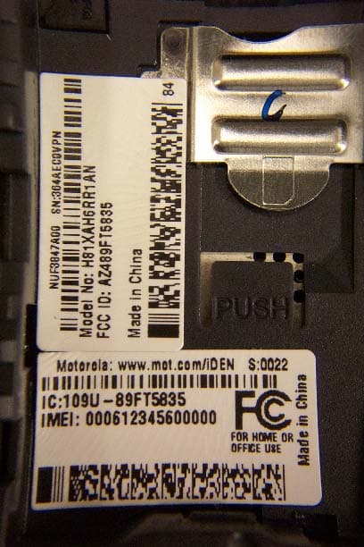
Click to zoom
Application Details
- Equipment Class
- TNE - Licensed Non-Broadcast Transmitter Held to Ear
- Date of Grant
- May 20, 2004
- Application Purpose
- Original Equipment
- Date of Application
- May 20, 2004
- Equipment Note
- ideni215
- Frequency Range
- 896.00000000 - 901.00000000
- Company
- Motorola Solutions, Inc.
- Country
- United States
Documents & Files
Document Text
Text extracted from the exhibit documents filed with the FCC. Open a document above to read the original.
Users Manual
i 215 Boost Mobile TM Phone User’s Guide FINAL DRAFT i ContentsIntroduction ................................................... 1 WelcometoBoostMobile TM - Wireless for a New Generation ........................................................... 1 Getting Started .............................................. 2 Opening the Battery Door .................................... 3Battery.................................................................. 5Powering On and Off ........................................... 7Enabling Over-the-Air Security ............................ 7Finding Your Phone Number ............................... 8Phone Basics ....................................................... 9SIM Security....................................................... 12Locking the Keypad ........................................... 14Accessories........................................................ 15Boost Mobile Customer Care............................. 15 Making Calls ................................................ 17 Receiving Calls .................................................. 17Call Icons ........................................................... 18Entering the Number to Call............................... 18Using Mute......................................................... 20Making Emergency Phone Calls........................ 20 Call Alerts .................................................... 22 Sending Call Alerts............................................. 22Receiving Call Alerts .......................................... 22Using the Call Alert Queue................................. 22 Recent Calls ................................................ 24 Storing Recent Calls to Contacts ....................... 24Deleting Recent Calls......................................... 25 Entering Text............................................... 26 Using Alpha Mode.............................................. 26Using Word Mode .............................................. 26Special Function Keys........................................ 27Using Numeric Mode.......................................... 28Using Symbols Mode ......................................... 28 Contacts ...................................................... 29 Viewing Contacts ............................................... 30Creating Entries ................................................. 31Storing Numbers Faster ..................................... 32Editing Entries .................................................... 33Deleting Entries.................................................. 33Checking Capacity ............................................. 33Creating Pauses and Waits................................ 33 ii International Numbers........................................ 34 Memo ............................................................ 35Advanced Calling Features ........................ 36 Call Hold ............................................................ 36Creating Pauses and Waits While Dialing ......... 36Making International Calls.................................. 37Setting One Touch Boost Walkie-Talkie ............ 37Call Timers......................................................... 38Making TTY Calls............................................... 38Special Dialing Codes........................................ 40 Boost Mobile TM Phone Services................ 41 Caller ID ............................................................. 41Per-Call Blocking ............................................... 41Per-Line Blocking............................................... 41Boost Mobile TM 411 ........................................... 41 Yellow Page Listings.......................................... 41Nationwide Call Completion............................... 42Driving Directions............................................... 42Restaurant Reservations ................................... 42Movie Listings and Show Times ........................ 42Local Event Information ..................................... 42 Ring Tones .................................................. 43 Setting Your Phone to Vibrate............................ 43Assigning Ring Tones to Contacts ..................... 44Ring and Vibrate ................................................ 44Viewing Ring Tone Assignments ....................... 44Downloading More Ring Tones.......................... 45Managing Memory ............................................. 45Deleting Custom Ring Tones ............................. 45 Message Center .......................................... 46 Accessing the Message Center ......................... 46Message Center Options ................................... 46 Receiving Messages................................... 47 Message Notifications ........................................ 47Message Center ................................................. 48 Voice Mail Messages .................................. 49 Receiving a Message ......................................... 49Accessing Voice Mail fromthe Message Center........................................... 49Sending Unanswered Calls to Voice Mail .......... 49 iii Boost Mobile Voice Mail ............................. 50 Setting Up Your Voice Mail Box......................... 50Changing Your Password .................................. 51Recording Your Name ....................................... 51Advanced Voice Mail Features .......................... 52 SMS and Boost Mobile TM Text and Numeric Messages ..................................................... 57 SMS Messages.................................................. 57Boost Mobile TM Text Messages and Web Alerts58 Boost Mobile TM Numeric Messages .................. 59 Boost Mobile Wireless Web Services........ 61 Starting the Microbrowser .................................. 61 Call Forwarding ........................................... 63 Forwarding All Calls .......................................…
Text truncated - open the document above for the full version.
Cover Letter(s)
FCC ID: AZ489FT5835 Motorola Inc., 8000 W. Sunrise Blvd., Plantation, FL 3332 http://www.mot.com/iDEN Page: 13-3 REQUEST FOR CONFIDENTIALITY 14th May 2004 Authorization & Evaluation Division Federal Communications Commission Laboratory 7435 Oakland Mills Road Columbia, MD 21046 Subject: Application for Type Acceptance of Transmitter with FCC ID: AZ489FT5835. Gentlemen; Motorola is requesting that Exhibit 4 (Circuit Description), Exhibit 5 (Schematic Diagrams), Exhibit 10 (Semiconductor/Active Device List) and Exhibit 12 not be made routinely available for public inspection. Motorola is in the process of licensing the technology and has a number of Patent applications pending. Please mark Exhibit 4, 5,10 and 12 as Confidential. Contact me at (954) 723-5793 if you require any additional information. Regards, /s/ Mike Ramnath (signed) FCC Liaison Email: [email protected]
Cover Letter(s)
FCC ID: AZ489FT5835 iDEN, Motorola Inc., 8000 W. Sunrise Blvd., Plantation, FL 33322 www.mot.com/iDEN Page: 13- 1 19 th May 2004 Authorization & Evaluation Division Federal Communications Commission Laboratory 7435 Oakland Mills Road Columbia, MD 21046 Gentlemen; Motorola Inc., 8000 West Sunrise Boulevard, Fort Lauderdale, Florida 33322, herein submits it’s application for Certification of the transmitter with FCC ID: AZ489FT5835. This variable output power (0.088 to 700 milliwatt) transmitter is part of a handheld transceiver used in a SMR and EA SMR trunking system operating in the United States 806-821/851- 866 MHz and 896-901/935-940 MHz frequency band. Certification is sought for this transceiver, and performance data is provided for that purpose. This transceiver is of the receive-first type described in International Telecommunications Union Recommendation ITU-R M.1221 entitled Technical and Operational Requirements for Cellular Multimode Mobile Radio Stations. It must first find, acquire and lock onto a control channel from a predefined set of control channel frequencies assigned to a companion Authorized base station (e.g. – FCC ID: ABZ89FC5792). Transmission is not possible until lock to a base station control channel has been achieved, then transmission is limited to digitally modulated service request bursts on the reverse control channel. Upon recognition of a proper request, the control channel base station transmitter will then assign the transceiver a traffic channel for transmission of digital voice or circuit-switched data from the set of frequencies for which the trunking system is licensed. Attached Exhibit 12.1 provides additional descriptive details. It is expected that this handheld time division multiplexed transceiver marketed in the United States will also be used for itinerant operation with companion Authorized Base Stations by users requesting trunked radio and telephone interconnect service while roaming outside the United States. In some countries the companion base stations are licensed to operate at frequencies in the 821-825/866-870 MHz band in addition to some of those in the 806-821/851-866 MHz band normally used in United States SMR systems. Consequently, this transmitter has been designed to meet FCC requirements for operation in the 806-821 MHz band over the more global band of 806 - 825 MHz when used with a companion Authorized Base Station. Thus, performance data is provided to substantiate FCC compliant operation with a Companion Base Station over the broader 806 to 825 MHz band expected for global use of this handheld transceiver. To facilitate global roaming it is kindly requested that a note be provided in the Grant for Equipment Authorization, which states that this ‘receive first’ type of equipment is FCC ID: AZ489FT5835 iDEN, Motorola Inc., 8000 W. Sunrise Blvd., Plantation, FL 33322 www.mot.com/iDEN Page: 13- 1 compliant for transmitter operation over the broader range 806-825 MHz when used with a compatible Authorized Base Station. This will aid equipment authorization in foreign countries, which accept a United States FCC Grant for Equipment Authorization, yet not jeopardize United States public safety or cellular systems licensed to operate in the 821- 825 MHz frequency band since no compatible base station may be authorized on those frequencies in the United States. It is also expected that this transceiver type will be marketed outside the United States and brought into the United States for itinerant “roaming” operation on compatible 806 - 821 MHz base stations located within the United States. Consequently, upon receipt of Authorization, only those units of this equipment type authorized for marketing in countries outside the United States will also bear a label with the specified FCC identifier. In accordance with 47 CFR 2.1093(c) this transmitter may be used in “covered” SMR service so it has been subjected to routine environmental evaluation for RF exposure and found to be compliant with the limits specified in 47 CFR 2.1093(d)(2). The subject transmitter complies with 47 CFR 90.203 of the rules in that the operator cannot directly program transmit frequencies using only the unit's normally accessible external controls. This transceiver can function as a Part 15.3(r) computer peripheral device when functioning as an RF modem and connected to a computer via a data cable (ref: Exhibit 12.1). For this reason a Declaration of Conformity has been prepared and is provided on Page 5 of the User Manual in the Exhibit 8. Enclosed is a complete Certification application comprised of 14 Exhibits. Contact me at (954) 723-5793 if you require any additional information. Sincerely, /s/ Mike Ramnath (signed) Mike Ramnath Manager, Regulatory Compliance Email: [email protected]
External Photos
FCC Filing Package for Motorola i215 Transceiver FCC ID: AZ489FT5835 Exhibit 3. External Photographs -- Pursuant to 47 CFR 2.1033(c) 12 Photograph 3-1: Front view Photograph 3-2: Back view IDEN, Motorola Inc., 8000 W. Sunrise Blvd., Plantation, FL 33322, USA WWW.MOT.COM/iDEN Page: 3 - 1 FCC Filing Package for Motorola i215 Transceiver FCC ID: AZ489FT5835 Photograph 3-3: Button side view Photograph 3-4: No button side view IDEN, Motorola Inc., 8000 W. Sunrise Blvd., Plantation, FL 33322, USA WWW.MOT.COM/iDEN Page: 3 - 2 FCC Filing Package for Motorola i215 Transceiver FCC ID: AZ489FT5835 Photograph 3-5: Back view, battery cover removed. Figure 3-6: Zoom view of labels containing FCC ID and FCC Logo IDEN, Motorola Inc., 8000 W. Sunrise Blvd., Plantation, FL 33322, USA WWW.MOT.COM/iDEN Page: 3 - 3
ID Label/Location Info
FCC Filing Package for Motorola i215 Transceiver FCC ID: AZ489FT5835 Exhibit 1. Identification Label -- Pursuant to 47 CFR 2.925, 2.1065 and 2.1033(c) 11 1.1 Location Back side of the radio product unit chassis (Photograph 1.1). 1.2 Type The label is a white polyester film laminate with a pressure sensitive adhesive backing. The adhesive is a permanent type acrylic with minimum peel strength of 5 lbs/in. 1.3 Markings (Text) Enlarged view of label (showing FCC ID and manufacturer type number): Photograph 1.1: Location of label on back of unit’s housing (battery cover removed). Figure 1.2: Zoom view of labels containing FCC ID and FCC Logo IDEN, Motorola Inc., 8000 W. Sunrise Blvd., Plantation, FL 33322, USA WWW.MOT.COM/iDEN Page: 1- 1 FCC Filing Package for Motorola i215 Transceiver FCC ID: AZ489FT5835 Exhibit 1A. General Information 1A.1 Production Plans Quantity production is planned. 1A.2 Application References -- Pursuant to 47 CFR 2.948 and 2.1061 Reference is made to the following Motorola "Application References" 1. Open Area Test Site “OATS” (FCC Registration: 91932 / Industry of Canada: IC3679) 1A.3 Data Submittal Procedure Data located in Exhibit 6 is supplied in accordance with 47CFR2, Sub-part J and Part 90, Sub-parts I and Sub-part S of the Commission’s rules. 1A.4 Similar, currently Certified Transceiver FCC ID: AZ489FT5822 1A.5 Additional Considerations This radio product also integrates a receiver that will receive and process signals from Global Positioning System satellites. The radio product can also function as a Part 15.3(r) computer peripheral device when functioning as an RF modem when connected to a computer via a data cable accessory (Exhibit 12). A Declaration of Conformity in accordance with 47CFR2.1077 (a) is provided in Exhibit 8 as evidence of compliance with Part 15 requirements for these additional Class B digital device functionalities per 47CFR15.101 (a). Compliance with Part 15 requirements for the super heterodyne receiver has been determined by verification in accordance with 47CFR15.1. IDEN, Motorola Inc., 8000 W. Sunrise Blvd., Plantation, FL 33322, USA WWW.MOT.COM/iDEN Page: 1- 2
Internal Photos
FCC Filing Package for Motorola i215 Transceiver FCC ID: AZ489FT5835 Exhibit 9. Internal Photographs -- Pursuant to 47 CFR 2.1033(c) 12 Photograph 9-1: Front side view of Photograph 9-2: Back side view of radio PCB. radio PCB. IDEN, Motorola Inc., 8000 W. Sunrise Blvd., Plantation, FL 33322, USA WWW.MOT.COM/iDEN Page: 9- 1 FCC Filing Package for Motorola i215 Transceiver FCC ID: AZ489FT5835 Photograph 9-3: Front side view of radio PCB without factory applied shields. Photograph 9-4: Back side view of radio PCB without factory applied shields. IDEN, Motorola Inc., 8000 W. Sunrise Blvd., Plantation, FL 33322, USA WWW.MOT.COM/iDEN Page: 9- 2
Parts List/Tune Up Info
FCC Filing Package for Motorola i215 Transceiver FCC ID: AZ489FT5835 IDEN, Motorola Inc., 8000 W. Sunrise Blvd., Plantation, FL 33322, USA WWW.MOT.COM/iDEN Page: 10- 1 Confidentiality Requested Exhibit 10. -- Pursuant to 47 CFR 2.1033 10.1 Semiconductor/Active Device List -- 47 CFR 2.1033(c)(10) NOTE: To ensure production continuity, components from multiple sources have been qualified for manufacture. COMMENTS: The Motorola designators are production part numbers for active devices used in Motorola radios. These devices are either identical or derived from the device family listed under source. Service people do not have access to any cross-references or given any information on proprietary devices and are prevented from making unauthorized substitution. 10.2 Tune Up Procedure -- 47 CFR 2.1033(c)(9) All adjustments are software controlled and pre-set at the factory. The service concept is of field replaceable radio substitution. When a radio is determined to be faulty it is replaced. The faulty radio is then forwarded to a high technology center. There it is repaired and returned to the factory for tuning. Reference Designator Motorola Part # Vendor Part Number Device Type Circuit Application Operating Frequency Range (MHz) Source U502 5185633C35 SHS-B080I ASM-1103 Module Antenna Switch 806- 825, 896-902 MHz 851-870, 935-941 MHz Hitachi TDK U516 5185353D89 SKYX77214 Module Power Amplifier 806- 825, 896-902 MHz Skyworks U500 5185353D38 20F7832 10R9861 IC Up-mixer/Modulator 806- 825, 896-902 MHz IBM U600 5185143E02 5185956E44 SC51643VF PC51650VF IC Synthesizer/Baseband 0-625 MHz Motorola SPS (Freescale) U301 5185633C15 MQE9M0A860M V1311AZ0867 UCVA2-W02A Module VCO 806- 825, 896-902 MHz Murata Fujitsu Alps U300 5185633C30 5185633C53 VON1876P26USA YKD10MDC1721M1877A UCVA2XW02A Module VCO 1702-1740, 1870-1882 MHz Samsung Kyocera Alps Y601 5185143E66 CSX532T MTE3055A IT5325BE TCO-5822 Module TCXO 16.8MHz+/-2.25PPM Citizen NDK Rakon Toyocom U204 5185353D17 51R87512V01 66P2922 IC Prescaler Divider/Down-mixer 851-870, 935-941 MHz 1702-1740, 1870-1882 MHz 567.33-580, 623.33-627.33 MHz IBM U801 5195017D05 5195017D06 PC29935VKR2 PC29936VKR2 PC29936JKR2 IC DSP/CPU 0-109.2 MHz Motorola SPS (Freescale) U001 5109879E93 5188450M08 PTWL93013GHHR SC79990AVHR2 IC Power Management/Audio 0-19.44MHz TI Motorola SPS (Freescale)
RF Exposure Info
CGISS EME Form-SAR-Rpt-Rev. 3.00 Page 1 of 23 CGISS EME Test Laboratory 8000 West Sunrise Blvd Fort Lauderdale, FL. 33322 S.A.R. EME Compliance Test Report Part 1 of 2 Note: Based on the information and the testing results provided herein, the undersigned certifies that when used as stated in the operating instructions supplied, said product complies with the national and international reference standards and guidelines listed in section 2.0 of this report. Signature on File 5/13/04 ____________________________________________________________ _________________________ Ken Enger Date Approved Senior Resource Manager, Laboratory Director, CGISS EME Lab Note: This report shall not be reproduced without written approval from an officially designated representative of the Motorola EME Laboratory. Date of Report: May 13, 2004 Report Revision: Rev. A Manufacturer: Motorola Product Description: 1:6, 1:3, 81:120, 1:12 TDM; 64 QAM, 16 QAM & QPSK Modulation; 0.6 W Pulse average FCC ID: AZ489FT5835 Device Model: H81XAH6RR1AN/NUF3847A Certificate Number: 1449-01 Test Period: 4/7/04 – 4/14/04 Technician: Ed Church (EME Technician Electronics II) Responsible Eng: Stephen Whalen (Sr. EME Eng.) Author: Michael Sailsman (Global EME Regulatory Affairs Liaison) CGISS EME Form-SAR-Rpt-Rev. 3.00 Page 2 of 23 TABLE OF CONTENTS Part 1 of 2 1.0 Introduction 2.0 Reference Standards and Guidelines 3.0 Description of Test Sample 3.1 Test Signal 3.2 Test Output Power 4.0 Description of Test Equipment 4.1 Description of S.A.R Measurement System 4.2 Description of Phantom 4.2.1 Flat Phantom 4.2.2 SAM phantom 4.3 Simulated Tissue Properties 4.3.1 Type of Simulated Tissue 4.3.2 Simulated Tissue Composition 4.4 Test conditions 5.0 Probe Scan Procedures 5.1 Shortened scan rationale 5.2 Description of Test Procedure 5.3 Device Test Positions 5.3.1 Body 5.3.2 Head 5.3.3 Face 5.4 Test Position Photographs 6.0 Measurement Uncertainty 7.0 S.A.R. Test Results 7.1 S.A.R. results 7.2 Peak S.A.R. location 7.3 Highest S.A.R. results calculation methodology 8.0 Conclusion Part 2 of 2 Appendix A: Power Slump Data/Shortened scan Appendix B: Data Results Appendix C: Dipole System Performance Check Results Appendix D: Probe/Dipole Calibration Certificates Appendix E: Illustration of Body-worn Accessories Appendix F: Accessories and options test status and separation distances CGISS EME Form-SAR-Rpt-Rev. 3.00 Page 3 of 23 REVISION HISTORY Date Revision Comments 4/20/04 O Release of Prototype results 5/13/04 A Revised antenna gain results in section 3.0 CGISS EME Form-SAR-Rpt-Rev. 3.00 Page 4 of 23 1.0 Introduction This report details the utilization, test setup, test equipment, and test results of the Specific Absorption Rate (S.A.R.) measurements performed at the CGISS EME Test Lab for model number H81XAH6RR1AN/NUF3847A, FCC ID: AZ489FT5835. The applicable exposure environment is General Population/Uncontrolled. 2.0 Reference Standards and Guidelines This product is designed to comply with the following national and international standards and guidelines. • United States Federal Communications Commission, Code of Federal Regulations; 47CFR part 2 sub-part J • IEEE 1528, 2003 "Recommended Practice for Determining the Peak Spatial-Average Specific Absorption Rate (SAR) in the Human Head from Wireless Communications Devices: Measurement Techniques" • American National Standards Institute (ANSI) / Institute of Electrical and Electronic Engi- neers (IEEE) C95. 1-1992 • Institute of Electrical and Electronic Engineers (IEEE) C95.1-1999 Edition • International Commission on Non-Ionizing Radiation Protection (ICNIRP) 1998 • Ministry of Health (Canada) Safety Code 6. Limits of Human Exposure to Terminal frequency Electromagnetic Fields in the Frequency Range from 3 kHz to 300 GHz, 1999 • Australian Communications Authority Radiocommunications (Electromagnetic Radiation - Human Exposure) Standard 2003 • ANATEL, Brazil Regulatory Authority, Resolution 256 (April 11, 2001) "additional requirements for SMR, cellular and PCS product certification." CGISS EME Form-SAR-Rpt-Rev. 3.00 Page 5 of 23 3.0 Description of Test Sample (Horizontal and vertical reference lines intersecting at the acoustic output are marked in blue on the DUT) FCC ID: AZ489FT5835 is a digital multi-service data capable device that employs time division multiplexing transmission technology with a duty cycle ranging from 16.67% to 33.33% using 16-QAM modulation for voice or circuit data transmission. There is a Split 1:3 mode that operates using a 16.67% transmission duty cycle. Two 7.5ms pulses occur during the six time slots within the 90-msec frame format. This mode is available in both the 806-825MHz and 896-902MHz bands in the telephone interconnect mode only. Packet data transmission is also supported up to a maximum duty cycle of 67.5% using quad QPSK modulation. This device will be marketed to and used by the general population. This device may be used while held against the head in voice mode, in front of the face in PTT mode, and against the body in voice, PTT and data modes. FCC ID: AZ489FT5835 is capable of operating in the 806-825 MHz and 896-902MHz bands. Packet data transmission is not available while transmitting in the 896-902 MHz band. The rated power is 0.6 watts pulsed averaged. The maximum output is 0.7 watts pulsed average as defined by the upper limit of the production line final test station. CGISS EME Form-SAR-Rpt-Rev. 3.00 Page 6 of 23 FCC ID: AZ489FT5835 is offered with the following options and accessories: Antenna Description 90-00265 Fixed Top Helical 806 – 941 MHz ¼ wave antenna; 1.5cm (-0.25dBd @ 813MHz, 0.23dBd @ 896 MHz) Batteries SNN5705B 750mAh Lithium Ion Body-worn Accessories NNTN5510A Holster NNTN4747A Belt clip Applicable Audio accessories SYN8390B Privacy Earpiece and Mic NNTN4033A Privacy earpiece and Mic w/ PTT NSN6066A Remote speaker Mic NNTN4620A Silver Earbud SYN8146C Lightweight over the ear headset w/boom Mic SYN7875C Hearing Aid Neck …
Text truncated - open the document above for the full version.
RF Exposure Info
CGISS EME Form-SAR-Rpt-Rev. 3.00 Page 1 of 42 CGISS EME Test Laboratory 8000 West Sunrise Blvd Fort Lauderdale, FL. 33322 S.A.R. EME Compliance Test Report Part 2 of 2 Note: Based on the information and the testing results provided herein, the undersigned certifies that when used as stated in the operating instructions supplied, said product complies with the national and international reference standards and guidelines listed in section 2.0 of this report. Signature on File 4/21/2004 ____________________________________________________________ _________________________ Ken Enger Date Approved Senior Resource Manager, Laboratory Director, CGISS EME Lab Note: This report shall not be reproduced without written approval from an officially designated representative of the Motorola EME Laboratory. Certificate Number: 1449-01 Date of Report: April 20, 2004 Report Revision: Rev. O Manufacturer: Motorola Product Description: 1:6, 1:3, 81:120, 1:12 TDM; 64 QAM, 16 QAM & QPSK Modulation; 0.6 W Pulse average FCC ID: AZ489FT5835 Device Model: H81XAH6RR1AN/NUF3847A Test Period: 4/7/04 – 4/14/04 Technician: Ed Church (EME Technician Electronics II) Responsible Eng: Stephen Whalen (Sr. EME Eng.) Author: Michael Sailsman (Global EME Regulatory Affairs Liaison) CGISS EME Form-SAR-Rpt-Rev. 3.00 Page 2 of 42 APPENDIX A Power Slump Data/Shortened Scan CGISS EME Form-SAR-Rpt-Rev. 3.00 Page 3 of 42 DUT Power versus time data CGISS EME Form-SAR-Rpt-Rev. 3.00 Page 4 of 42 Shortened Scan Results FCC ID: AZ489FT5835; Test Date: 4/13/04 Motorola CGISS EME Laboratory Run #: EC-Ab-R1-040413-15 Model #: H81XAH6RR1AN SN: 364KEC00DW TX Freq: 813.5125 MHz Tissue Temp: 20.9 (Celsius) Start Power: .690 W Antenna: Fixed - STUBBY Battery Kit: SNN5705B Carry Case: Holster NNTN5510A Audio/Data Acc.: None Shortened scan reflect highest S.A.R. producing configuration; Run time 8 minutes. Representative “normal” scan run time was 23 minutes “Shortened” scan max calculated S.A.R. using S.A.R. drift: 1-g Avg. = 1.46mW/g; 10-g Avg. = 1.04mW/g “Normal” scan max calculated S.A.R. using S.A.R. drift: 1-g Avg. = 1.57mW/g; 10-g Avg. = 1.13mW/g (see section 7.1 run # EC-Ab-R1-040413-12) DUT with carry case against phantom Flat Phantom; Device Section; Position: (90°,90°); Probe: ET3DV6 - SN1384(Cal Date 05-15-2003); ConvF(6.50,6.50,6.50); Probe cal date: 15/05/03; Crest factor: 1.5; FCC Body 813 MHz: σ = 0.96 mho/m ε = 54.7 ρ = 1.00 g/cm3; DAE3: 363V1 DAE Cal Date: 05/13/2003 Cube 5x5x7: SAR (1g): 1.29 mW/g, SAR (10g): 0.920 mW/g, (Worst-case extrapolation) Cube 5x5x7: Dx = 8.0, Dy = 8.0, Dz = 5.0; SAR (1g): 1.29 mW/g, SAR (10g): 0.920 mW/g Power Drift: -0.46 dB CGISS EME Form-SAR-Rpt-Rev. 3.00 Page 5 of 42 FCC ID: AZ489FT5835; Test Date: 4/14/04 Motorola CGISS EME Laboratory Run #: EC- Lear-R1-040414-11 Model #: H81XAH6RR1AN SN: 364KEC00D4 TX Freq: 806.0125 MHZ Tissue Temp: 20.9 (Celsius) Start Power: .700 W Antenna: Fixed - STUBBY Battery Kit: SNN5705B Carry Case: None Audio/Data Acc.: None Shortened scan reflect highest S.A.R. producing configuration; Run time 8 minutes. Representative “normal” scan run time was 25 minutes “Shortened” scan max calculated S.A.R. using S.A.R. drift: 1-g Avg. = 1.41mW/g; 10-g Avg. = 0.96mW/g “Normal” scan max calculated S.A.R. using S.A.R. drift: 1-g Avg. = 1.41mW/g; 10-g Avg. = 0.98mW/g (see section 7.1 run # EC-Ab-R1-040407-03) DUT at the left ear in cheek touch position SAM Phantom; Left Head Section; Position: (90°,301°); Probe: ET3DV6 - SN1384(Cal Date 05-15-2003); ConvF(6.60,6.60,6.60); Probe cal date: 15/05/03; Crest factor: 3.0; IEEE Head 813 MHz: σ = 0.93 mho/m ε = 42.1 ρ = 1.00 g/cm3; DAE3: 363V1 DAE Cal Date: 05/13/2003 Cube 5x5x7: SAR (1g): 1.41 mW/g, SAR (10g): 0.960 mW/g, (Worst-case extrapolation) Cube 5x5x7: Dx = 8.0, Dy = 8.0, Dz = 5.0; SAR (1g): 1.41 mW/g, SAR (10g): 0.960 mW/g Power Drift: 0.06 dB CGISS EME Form-SAR-Rpt-Rev. 3.00 Page 6 of 42 APPENDIX B Data Results CGISS EME Form-SAR-Rpt-Rev. 3.00 Page 7 of 42 FCC ID: AZ489FT5835; Test Date: 4/7/04 Motorola CGISS EME Laboratory Run #: EC- Lear-R1-040407-03 Model #: H81XAH6RR1AN SN: 364KEC00D4 TX Freq: 813.5125 MHZ Tissue Temp: 20.5 (Celsius) Start Power: .700 W Antenna: Fixed - STUBBY Battery Kit: SNN5705B Carry Case: None Audio/Data Acc.: None DUT at left ear in cheek touch position SAM Phantom; Left Head Section; Position: (90°,59°); Probe: ET3DV6 - SN1384(Cal Date 05-15-2003); ConvF(6.60,6.60,6.60); Probe cal date: 15/05/03; Crest factor: 3.0; IEEE Head 813 MHz: σ = 0.93 mho/m ε = 41.8 ρ = 1.00 g/cm3; DAE3: 363V1 DAE Cal Date: 05/13/2003 Cube 7x7x7: SAR (1g): 1.41 mW/g, SAR (10g): 0.976 mW/g, (Worst-case extrapolation) Coarse: Dx = 15.0, Dy = 15.0, Dz = 10.0; Max at 90.0, 31.5, 4.7 Power Drift: 0.18 dB CGISS EME Form-SAR-Rpt-Rev. 3.00 Page 8 of 42 FCC ID: AZ489FT5835; Test Date: 4/8/04 Motorola CGISS EME Laboratory Run #: EC-Face-R1-040408-20 Model #: H81XAH6RR1AN SN: 364KEC00D4 TX Freq: 806.0125 MHZ Tissue Temp: 20.7 (Celsius) Start Power: .711 W Antenna: Fixed - STUBBY Battery Kit: SNN5705B Carry Case: None Audio/Data Acc.: None DUT front towards phantom w/ 2.5 cm separation SAM Phantom; Flat Section; Position: (90°,90°); Probe: ET3DV6 - SN1384(Cal Date 05-15-2003); ConvF(6.60,6.60,6.60); Probe cal date: 15/05/03; Crest factor: 6.0; IEEE Head 813 MHz: σ = 0.93 mho/m ε = 41.8 ρ = 1.00 g/cm3; DAE3: 363V1 DAE Cal Date: 05/13/2003 Cube 7x7x7: SAR (1g): 0.573 mW/g, SAR (10g): 0.402 mW/g, (Worst-case extrapolation) Coarse: Dx = 15.0, Dy = 15.0, Dz = 10.0; Max at 39.0, 75.0, 4.7 Power drift: 0.03 dB CGISS EME Form-SAR-Rpt-Rev. 3.00 Page 9 of 42 FCC ID: AZ489FT5835; Test Date: 4/8/04 Motorola CGISS EME Laboratory Run #: EC-Lear-R1-040408-14 Model #: H81XAH6RR1AN SN: 364KEC00D4 TX Freq: 896.01875 MHZ Tissue Temp: 20.9 (Celsius) Start Power: .695 W Antenna: Fixed - STUBBY Battery Kit: SNN5705B Carry Case: None Audio/Data Acc.: None DUT at left ear in Cheek Touch position SAM Phantom; Left Head Section; Position: (90°,59°); Probe: ET3DV6 -…
Text truncated - open the document above for the full version.
Test Report
FCC Filing Package for Motorola i215 Transceiver FCC ID: AZ489FT5835 Exhibit 6. Measured Data -- Pursuant 47 CFR. 2.1041 6.1 Transmitter Power The transmitter is a variable power type used in a SMR trunking system. Output power (as defined in 47 CFR 90.7) is dynamically controlled as described in Exhibit 12. 6.1.1 Maximum Output Power Rating -…
Text truncated - open the document above for the full version.
Contact Information
Applicant
Deanna Zakharia(Regulatory Compliance Manager)
Test Firm
MotorolaWilliam Elliott
Technical Specifications
| # | Rule Parts | Frequency Range | Power Output | Emission | Tolerance |
|---|---|---|---|---|---|
| 2 | 9 | 896 MHz - 901 MHz | 700.00 mW | 18K3D7W | 0.5 ppm |
Other Applications from Motorola Solutions, Inc.

AZ489FT4980
Sep 08, 2026Portable two way radio
Equipment Class
TNF - Licensed Non-Broadcast Transmitter Held to FaceAZ489FT4981
Aug 14, 2026Handheld Portable - TANAPA BPR 45 400-470 MHZ 4W NKP
Equipment Class
TNF - Licensed Non-Broadcast Transmitter Held to Face
AZ489FT7187
Jul 13, 2026Portable 2-Way Radio with Bluetooth, Bluetooth LE, WIFI 2.4GHz, WIFI 5GHz, LTE
Equipment Class
DSS - Part 15 Spread Spectrum TransmitterAZ499FT6031
May 11, 2026Operation Critical Wireless Earpiece PTT
Equipment Class
DSS - Part 15 Spread Spectrum Transmitter
AZ499FT5879
Dec 19, 20252-way Portable Radio with BT, BTLE, WIFI, NFC and LTE
Equipment Class
DSS - Part 15 Spread Spectrum Transmitter