AZ489FT5837ATS2500, PMUF1063B, 1064B
Motorola Solutions, Inc.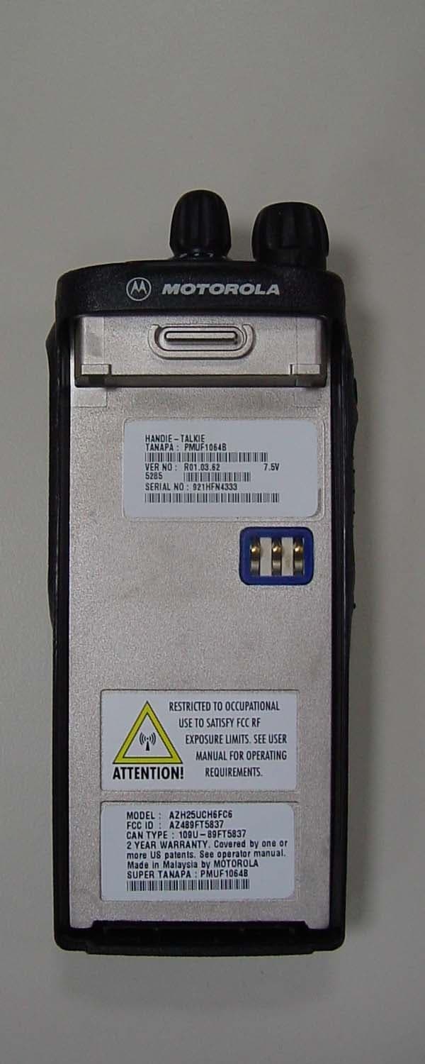
Click to zoom
Application Details
- Equipment Class
- TNF - Licensed Non-Broadcast Transmitter Held to Face
- Date of Grant
- Nov 06, 2005
- Application Purpose
- Original Equipment
- Date of Application
- Nov 06, 2005
- Equipment Note
- ATS2500, PMUF1063B, 1064B
- Frequency Range
- 851.00000000 - 870.00000000
- Company
- Motorola Solutions, Inc.
- Country
- United States
Documents & Files
Document Text
Text extracted from the exhibit documents filed with the FCC. Open a document above to read the original.
Users Manual
1 CONTENTS CONTENTS Radio Overview . . . . . . . . . . . . . . . . . . . . 4 Operation and Control Functions. . . . . . . . 5 Radio Controls . . . . . . . . . . . . . . . . . . . 5 Programmable Buttons. . . . . . . . . . . . . 7 Keypad Keys (for Model II radios only). 8 Menu Keys (for Model II radios only) . . 9 Selecting a Feature. . . . . . . . . . . . . . . . 9 Menu Display . . . . . . . . . . . . . . . . . . . 10 LCD Screen and Icons . . . . . . . . . . . . 10 Alert Tone Indications. . . . . . . . . . . . . 11 Getting Started. . . . . . . . . . . . . . . . . . . . 13 Battery Information. . . . . . . . . . . . . . . . . . 13 Battery Care and Tips. . . . . . . . . . . . . 13 Recycling or Disposal of Batteries . . . 14 Charging the Battery. . . . . . . . . . . . . . 14 Accessory Information . . . . . . . . . . . . . . . 15 Attaching the Battery. . . . . . . . . . . . . . 15 Removing the Battery. . . . . . . . . . . . . 15 Attaching the Antenna. . . . . . . . . . . . . 16 Removing the Antenna. . . . . . . . . . . . 16 Attaching the Belt Clip. . . . . . . . . . . . . 17 Removing the Belt Clip. . . . . . . . . . . . 17 Attaching the Dust Cover . . . . . . . . . . 18 Radio Operation . . . . . . . . . . . . . . . . . . . .19 Turning The Radio On or Off . . . . . . . .19 Adjusting the Radio’s Volume. . . . . . . .19 Radio Self Test. . . . . . . . . . . . . . . . . . .19 Basic Radio Calls . . . . . . . . . . . . . . . . . .20 Selecting a Zone and Mode. . . . . . . . . . . .20 Selecting a Zone (for Model II radios only). . . . . . . . . . . .20 Selecting a Mode . . . . . . . . . . . . . . . . .20 Receiving a Call. . . . . . . . . . . . . . . . . . . . .21 Making a Call. . . . . . . . . . . . . . . . . . . . . . .21 Conventional Modes. . . . . . . . . . . . . . .21 Trunked Modes. . . . . . . . . . . . . . . . . . .21 Low-Battery Alert . . . . . . . . . . . . . . . . .22 Coded Squelch Operation . . . . . . . . . .22 Variable RF Power Level (Selected Models Only) . . . . . . . . . . . .22 Failsoft Operation (Trunked Systems Only) . . . . . . . . . . . . . .22 Muting the Keypad Tones (for keypad Radios only) . . . . . . . . . . . . . .23 Trunked Features . . . . . . . . . . . . . . . . . .24 Viewing Your Radio’s ID Number . . . . . . .24 Enhanced Private Call Operation . . . . . . .24 ATS2500 .book Page 1 Monday, December 18, 2000 7:39 PM 2 CONTENTS Answering a Private Call. . . . . . . . . . . 24 Making a Private Call . . . . . . . . . . . . . 25 Leaving a Call Alert Page. . . . . . . . . . 28 Call Alert Operation . . . . . . . . . . . . . . . . . 28 Answering a Call Alert Page with a Group Call . . . . . . . . . . . . . . . . . . . . . . . . . . . 28 Making a Call Alert . . . . . . . . . . . . . . . 29 Automatic Multiple Site Selection (AMSS)31 Viewing the Current Site. . . . . . . . . . . 31 Forcing a Site Change . . . . . . . . . . . . 32 Locking and Unlocking a Site . . . . . . . 32 Conventional Features . . . . . . . . . . . . . 33 Repeat/Direct. . . . . . . . . . . . . . . . . . . . . . 33 Smart PTT . . . . . . . . . . . . . . . . . . . . . . . . 33 Scan. . . . . . . . . . . . . . . . . . . . . . . . . . . . . 35 Scan Operation . . . . . . . . . . . . . . . . . . . . 35 Turning Scan On or OFF with the Keypad (for Keypad radios only) . . . . . . . . . . . 35 Deleting Nuisance Modes. . . . . . . . . . 36 Viewing a Scan List (for keypad radios only) . . . . . . . . . . . 36 Programming a Scan List (for keypad radios only) . . . . . . . . . . . 37 Scan Modes . . . . . . . . . . . . . . . . . . . . 38 Programming the Radio . . . . . . . . . . . . .39 Programming the Telephone List Numbers . . . . . . . . . . .39 Programming the Call List . . . . . . . . . .40 Telephone Operation. . . . . . . . . . . . . . . .42 Answering a Telephone Call. . . . . . . . .42 Making a Telephone Call (for Model II radios only). . . . . . . . . . . .42 Special Features . . . . . . . . . . . . . . . . . . .46 Emergency Operation . . . . . . . . . . . . . . . .46 Sending an Emergency Alarm . . . . . . .46 Sending a Silent Emergency Alarm . . .47 Canceling an Emergency Alarm. . . . . .47 Sending an Emergency Call. . . . . . . . .47 Ending an Emergency Call. . . . . . . . . .48 Emergency with Voice to Follow. . . . . .48 Dynamic Regrouping. . . . . . . . . . . . . . . . .48 Mode Selection. . . . . . . . . . . . . . . . . . .48 Select Enable and Disable. . . . . . . . . .49 SmartZone Operation . . . . . . . . . . . . . . .50 Benefits of SmartZoneTM . . . . . . . . . . . . .50 Site Switching in SmartZone . . . . . . . .51 Viewing the Current Site. . . . . . . . . . . .52 ATS2500 .book Page 2 Monday, December 18, 2000 7:39 PM 3 CONTENTS Forcing a Site Change . . . . . . . . . . . . 52 Locking and Unlocking a Site . . . . . . . 52 Preferred Site Selection . . . . . . . . . . . 52 Busy Override. . . . . . . . . . . . . . . . . . . 53 Site Trunking. . . . . . . . . . . . . . . . . . . . 54 Stat-Alert Features. . . . . . . . . . . . . . . . . 55 Viewing Your Radio’s ID Number. . . . . . . 55 Stat-Alert Voice Selective Call Operation. 55 Receiving a Voice Selective Call . . . . 56 Making a Voice Selective Call. . . . . . . 56 Stat-Alert Call Alert Operation . . . . . . . . . 58 Receiving a Call Alert Page . . . . . . . . 58 Making a Call Alert . . . . . . . . . . . . . . . 59 PTT-ID. . . . . . . . . . . . . . . . . . . . . . . . . . . .60 Radio Check . . . . . . . . . . . . . . . . . . . . . . .60 Emergency Operation . . . . . . . . . . . . . . . .60 ATS2500 .book Page 3 Monday, December 18, 2000 7:39 PM RADIO OVER VIE W 4 RADIO OVERVIEW This user guide covers the operation of the ATS 2500 Portable Radio. Please read the “Safety Information” on pages 61 to 64 before using this radio. 2. On-Off / Volume Knob 9. Microphone 4. Push to Talk (PTT) 8. LED Indicator 5. Side Button 2 6. Side Button 3 1. Mode Selector Knob 7. Top Button 10. Antenna Connector 11. Dust Cover Button covering Accessory 3. Side Button 1/ Model I Select Key ATS…
Text truncated - open the document above for the full version.
Users Manual
English Product Safety and RF Energy Exposure Booklet for Portable Two-Way Radios The information provided in this document supersedes the general safety information contained in user guides published prior to February 2002. BEFORE USING THIS RADIO, READ THIS BOOKLET WHICH CONTAINS IMPORTANT OPERATING INSTRUCTIONS FOR SAFE USAGE AND RF ENERGY AWARENESS AND CONTROL INFORMATION AND OPERATIONAL INSTRUCTIONS FOR COMPLIANCE WITH RF ENERGY EXPOSURE LIMITS IN APPLICABLE NATIONAL AND INTERNATIONAL STANDARDS. ALSO READ THE OPERATIONAL INSTRUCTIONS FOR SAFE USAGE. FOR RADIOS THAT HAVE BEEN APPROVED AS INTRINSICALLY SAFE, READ THE INSTRUCTIONS AND INFORMATION ON INTRINSIC SAFETY ON PAGE 10 OF THIS BOOKLET. ! C a u t i o n © Motorola, Inc. 2004 8000 W. Sunrise Blvd., Ft. Lauderdale, FL 33322 68P81095C98 68P81095C98-C 95C98-C.book Page 1 Wednesday, October 27, 2004 11:59 AM 2 English RF Energy Exposure Awareness and Control Information and Operational Instructions for Occupational Use NOTICE: This radio is intended for use in occupational/controlled conditions where users have full knowledge of their exposure and can exercise control over their exposure to meet the occupational limits in FCC and International standards. This radio device is NOT authorized for general population consumer use. This two-way radio uses electromagnetic energy in the radio frequency (RF) spectrum to provide communications between two or more users over a distance. It uses radio frequency (RF) energy or radio waves to send and receive calls. RF energy is one form of electromagnetic energy. Other forms include, but are not limited to, sunlight and x-rays. RF energy, however, should not be confused with these other forms of electromagnetic energy, which when used improperly, can cause biological damage. Very high levels of x-rays, for example, can damage tissues and genetic material. Experts in science, engineering, medicine, health, and industry work with organizations to develop standards for safe exposure to RF energy. These standards provide recommended levels of RF exposure for both workers and the general public. These recommended RF exposure levels include substantial margins of protection. All Motorola two-way radios are designed, manufactured, and tested to ensure they meet government-established RF exposure levels. In addition, manufacturers also recommend specific operating instructions to users of two-way radios. These instructions are important because they inform users about RF energy exposure and provide simple procedures on how to control it. 95C98-C.book Page 2 Wednesday, October 27, 2004 11:59 AM 3 English Please refer to the following websites for more information on what RF energy exposure is and how to control your exposure to assure compliance with established RF exposure limits: http://www.fcc.gov/oet/rfsafety/rf-faqs.html http://www.osha.gov/SLTC/radiofrequencyradiation/index.html Federal Communication Commission (FCC) Regulations The FCC rules require manufacturers to comply with the FCC RF energy exposure limits for portable two-way radios before they can be marketed in the U.S. When two-way radios are used as a consequence of employment, the FCC requires users to be fully aware of and able to control their exposure to meet occupational requirements. Exposure awareness can be facilitated by the use of a product label directing users to specific user awareness information. Your Motorola two-way radio has a RF Exposure Product Label. Also, your Motorola user manual, or separate safety booklet includes information and operating instructions required to control your RF exposure and to satisfy compliance requirements. Compliance with RF Exposure Standards Your Motorola two-way radio is designed and tested to comply with a number of national and International standards and guidelines (listed below) for human exposure to radio frequency electromagnetic energy. This radio complies with the IEEE (FCC) and ICNIRP exposure limits for occupational/controlled RF exposure environments at operating duty factors of up to 50% talk-50% listen and is authorized by the FCC for occupational use only. In terms of measuring RF energy for compliance with these exposure guidelines, your radio generates measurable RF energy only while it is transmitting (during talking), not when it is receiving (listening) or in standby mode. NOTE:The approved batteries, supplied with this radio, are rated for a 5-5-90 duty factor (5% talk-5% listen-90% standby) even though this radio complies with FCC occupational exposure limits and may operate at duty factors of up to 50% talk. 95C98-C.book Page 3 Wednesday, October 27, 2004 11:59 AM 4 English Your Motorola two-way radio complies with the following RF energy exposure standards and guidelines: • United States Federal Communications Commission, Code of Federal Regulations; 47CFR part 2 sub-part J • American National Standards Institute (ANSI) / Institute of Electrical and Electronic Engineers (IEEE) C95. 1-1992 • Institute of Electrical and Electronic Engineers (IEEE) C95.1-1999 Edition • International Commission on Non-Ionizing Radiation Protection (ICNIRP) 1998 • Ministry of Health (Canada) Safety Code 6. Limits of Human Exposure to Radiofrequency Electromagnetic Fields in the Frequency Range from 3 kHz to 300 GHz, 1999 • Australian Communications Authority Radiocommunications (Electromagnetic Radiation – Human Exposure) Standard, 2003 • ANATEL ANNEX to Resolution No. 303 of July 2, 2002 "Regulation of limitation of exposure to electrical, magnetic and electromagnetic fields in the radio frequency range between 9 KHz and 300 GHz" and "Attachment to resolution # 303 from July 2, 2002" RF Exposure Compliance and Control Guidelines and Operating Instructions To control your exposure and ensure compliance with the occupational/controlled environment exposure limits, always adhere to the following procedures. Guidelines: • Do not remove the RF Exposure Label from the device. • User awareness i…
Text truncated - open the document above for the full version.
Cover Letter(s)
REQUEST FOR CONFIDENTIALITY Date: 2 nd November 2005 Authorization & Evaluation Division Federal Communications Commission Laboratory 7435 Oakland Mills Road Columbia, MD 21046 Request for Confidentiality for Transmitter with FCC ID: AZ489FT5837 Dear Sir / Madam, Motorola is requesting that Exhibit 4 (Circuit Descriptions), Exhibit 5 (Schematic Diagrams), Exhibit 10 (Parts List and Tune Up Procedures) and Exhibit 12 (Operational Description) not be made routinely available for public inspection. Motorola considers the information in these exhibits to be classified as trade secrets, pursuant to 47 CFR Section 0.457(d) and Section 552(b)(4) of the Freedom of Information Act. Please mark Exhibits 4, 5, 10 and 12 as “Confidential.” Please contact me at 954-723-5793 if you require any additional information. Sincerely, /s/ Mike Ramnath (signed) Manager, Regulatory Compliance Email: [email protected] EXHIBIT 13B SHEET 1
Cover Letter(s)
Date: 2 nd November 2005 Authorization & Evaluation Division Federal Communications Commission Laboratory 7435 Oakland Mills Road Columbia, MD 21046 Application for Certification of Transmitter with FCC ID: AZ489FT5837 Dear Sir / Madam, Motorola Inc., 8000 West Sunrise Blvd., Fort Lauderdale, FL, herein submits application for Certification of the equipment identified by FCC ID: AZ489FT5837. This transmitter is primarily intended for use in a portable radio application with capabilities for conventional communications with a conducted transmit power which is adjustable from 1 Watts (+30 dBm) to 2.95 Watts (+34.7 dBm) for frequency range 806 – 869 MHz. The subject transmitter complies with CFR Title 47, Section 90.203, in that the operator cannot directly program the transmit frequencies using only the normally accessible external controls of the unit. Enclosed is a complete Certification Application. Please contact me at 954-723-5793 if you require any additional information. Sincerely, /s/ Mike Ramnath (signed) Manager, Regulatory Compliance Email: [email protected] EXHIBIT 13A SHEET 1 OF 1
External Photos
Applicant: Motorola Inc. FCC ID: AZ489FT5837 EXHIBIT 3 SHEET 1 OF 5 EXTERNAL PHOTOGRAPH Pursuant to 47 CFR 2.1033(c) 12 Figure 3-1: Front view of complete radio (Preferred Keypad). Applicant: Motorola Inc. FCC ID: AZ489FT5837 EXHIBIT 3 SHEET 2 OF 5 Figure 3-2: Front view of complete radio (Popular Keypad). Applicant: Motorola Inc. FCC ID: AZ489FT5837 EXHIBIT 3 SHEET 3 OF 5 Figure 3-3: Back view of complete radio. Applicant: Motorola Inc. FCC ID: AZ489FT5837 EXHIBIT 3 SHEET 4 OF 5 RF Safety Label Location FCC Label Location Figure 3-6: Rear view of complete radio showing FCC Label Applicant: Motorola Inc. FCC ID: AZ489FT5837 EXHIBIT 3 SHEET 5 OF 5 Model List Model Number Super Tanapa Name Plate Description AZH25UCC6FC3 PMUF1063A ATS2500 800 MHz 2.5W 25 kHz 1.5PPM AZH25UCH6FC6 PMUF1064A ATS2500 800 MHz 2.5W 25 kHz DISP 1.5PPM
ID Label/Location Info
Applicant: Motorola Inc. FCC ID: AZ489FT5837 EXHIBIT 1 SHEET 1 OF 1 IDENTIFICATION LABEL Pursuant to 47 CFR 2.925(a), 2.1033(c), 2.0165 LOCATION A nameplate of the type presented below will be affixed to every transmitter. It will be placed on the bottom of the unit near the front. Shown below is a photo of the actual label affixed to the cast chassis of the transmitter. TYPE The label is a paper polyester film laminate with a pressure sensitive adhesive backing. The adhesive is a permanent type acrylic with minimum peel strength of 40 oz/inch. EXHIBIT 1A – GENERAL INFORMATION 1. Application References: TIA/EIA-603 Land Mobile FM or PM Communications Equipment Measurement and Performance Standards Code of Federal Regulations Title 47, Part 2, Sec. 2.1033-2.1057, and Part 90, Section 90.210. 2. Data Submittal Procedure: Data is supplied in accordance with Part 2, Sub-part J of the Commission’s rules. The intended use of this transceiver includes applications covered in the Code of Federal Regulations Title 47, Part 90. Maximum transmitter power shall not be adjustable by the user.
Internal Photos
Applicant: Motorola Inc. FCC ID: AZ489FT5837 EXHIBIT 9 SHEET 1 OF 4 INTERNAL PHOTOGRAPH Pursuant to 47 CFR 2.1033(c) 12 Figure 9-1: Top Side of RF PCB with shields. Figure 9-2: Bottom Side of RF PCB with shields. Applicant: Motorola Inc. FCC ID: AZ489FT5837 EXHIBIT 9 SHEET 2 OF 4 Figure 9-3: Top Side of RF PCB Figure 9-4: Bottom Side of RF PCB. Applicant: Motorola Inc. FCC ID: AZ489FT5837 EXHIBIT 9 SHEET 3 OF 4 Figure 9-3: Top Side of Controller PCB. Applicant: Motorola Inc. FCC ID: AZ489FT5837 EXHIBIT 9 SHEET 4 OF 4 Figure 9-4: Bottom Side of Controller PCB.
Test Report
AZ489FT5837 SR2859_60 GEMS EME Form-SAR-Rpt-Rev. 4.00 Page 1 of 30 Certificate Number: 1449-01 FCC ID: AZ489FT5837 DECLARATION OF COMPLIANCE SAR ASSESSMENT Part 1 of 3 Government & Enterprise Mobility Solutions EME Test Laboratory 8000 West Sunrise Blvd Fort Lauderdale, FL. 33322 Date of Report: October 11, 2005 Report Revision: Rev. O Report ID: FCC rpt_ATS2500_Rev O_051011 SR2859_60 Responsible Engineer: Deanna Zakharia (Elect. Principle Staff Eng.) Date/s Tested: 9/16/2005 – 9/30/2005 Manufacturer/Location: Motorola, Penang Sector/Group/Div.: GEMS Date submitted for test: 9/7/2005 DUT Description: Portable transceiver 800MHz 2.5W; POP & Pref KP; 1.5PPM Test TX mode(s): CW Max. Power output: 2.95W (806-824MHz band); 2.40W (851-870MHz band) Nominal Power: 2.5W (806-824MHz band); 2.0W (851-870MHz band) Tx Frequency Bands: 806-824MHz; 851-870MHz Signaling type: FM Model(s) Tested: PMUF1063B & PMUF1064B Model(s) Certified: PMUF1063B & PMUF1064B Serial Number(s): 921HFN4312, 921HFN4298, 921HFN4333(PMUF1064B) Classification: Occupational/Controlled Rule Part(s): 90 Approved Accessories: Antenna(s): PMAF4000A (Whip 806-870MHz ½ wave; -3.0dBd); PMAF4001A (Stubby 806-941MHz ¼ wave) Battery(ies): HNN9008A (NiMH High Cap.), HNN9009A (NiMH Ultra High Cap.), HNN9010A (NiMH Ultra High Cap. FM), HNN9011A (NiCd High Cap. FM), HNN9012A (NiCd High Cap), HNN9013B (Li Ion High Cap.), HNN9013D (Li Ion High Cap.), PMNN4045BR (NiMH 1400mAH MAGONE) Body worn accessory: HLN9652A (Short, Plain, belt loop, thin bat.), HLN9665A (Short, Plain, belt loop, std bat.), HLN9670A (Short, Plain, swivel, thin bat), HLN9676A (Short, Plain, swivel, Std bat.), HLN9677A (Short, DTMF, belt loop, thin bat.), HLN9689A (Short, DTMF, belt loop, std. bat), HLN9690A (Short, DTMF, swivel, thin bat.), HLN9694A (Short, DTMF, swivel, std. bat.), HLN9701B (Short, Plain, belt loop, thin bat), NTN8039B (Belt swivel 2.5”), HLN9714A (Spring belt clip for 2.5” belt width), HLN9844A (Spring belt clip for 1.5” belt width), HLN9945A (Limited keypad, hard leather, w/ belt loop, thin bat.), HLN9946A (Limited keypad, hard leather, w/belt loop, std. bat), HLN9955A (Limited keypad, hard leather, w/swivel, thin bat), HLN9998A (Limited keypad, hard leather, w/swivel, std. bat.), NTN5243A (Carry strap), RLN4815A (Fanny pack carry acc., Universal radio pack), PMLN4280A (Carry case, Full thin leather), HLN9952A (Belt clip carry holder) Audio Accessories See section 3.0 for list of approved audio acc. Max. Calc. 1-g/10-g Avg. SAR: 4.79/3.51 mW/g (Body-worn) Max. Calc. 1-g/10-g Avg. SAR: 1.83/1.33 mW/g (Face) Based on the information and the testing results provided herein, the undersigned certifies that when used as stated in the operating instructions supplied, said product complies with the national and international reference standards and guidelines listed in section 2.0 of this report. This report shall not be reproduced without written approval from an officially designated representative of the Motorola EME Laboratory. This reporting format is consistent with the test report guidelines of the TIA TSB-150 December 2004 The results and statements contained in this report pertain only to the device(s) evaluated. Signature on file – Ken Enger Ken Enger GEMS EME Lab Senior Resource Manager, Laboratory Director, Approval Date: 10/12/2005 Certification Date: 10/12/2005 Certification No.: L1051012 & L1051013 AZ489FT5837 SR2859_60 GEMS EME Form-SAR-Rpt-Rev. 4.00 Page 2 of 30 Part 1 of 2 1.0 Introduction and Overview .......................................................................................... 3 2.0 References, Standards, and Guidelines ........................................................................ 3 2.1 SAR Limits ............................................................................................................... 4 3.0 Description of Device Under Test (DUT).................................................................... 4 4.0 Description of Test System .......................................................................................... 6 4.1 Description of Robotics/Probes/Readout Electronics ............................................... 6 4.2 Description of Phantom(s) ........................................................................................ 7 4.3 Description of Equivalent Tissues ............................................................................ 7 5.0 Additional Test Equipment ......................................................................................... 8 6.0 SAR Measurement System Verification ..................................................................... 8 6.1 Equivalent Tissue Test results.................................................................................. 8 6.2 System Check Test results ....................................................................................... 9 7.0 DUT Test Strategy and Methodology ......................................................................... 9 7.1 Test Plan................................................................................................................... 9 7.2 Device Positioning Procedures .............................................................................. 10 8.0 Environmental Test Conditions................................................................................. 11 9.0 Test Results Summary............................................................................................... 11 9.1 Highest S.A.R. results calculation methodology.................................................... 17 10.0 Conclusion ...............................................................................................................17 APPENDICES A Measurement Uncertainty...............................................................18 B Probe Calibration Certificates...........................................................21 Part 2 of 3 C. Dipole Calibration Certificates..................…
Text truncated - open the document above for the full version.
Test Report
AZ489FT5837 SR2859_60 GEMS EME Form-SAR-Rpt-Rev. 4.00 Page 1 of 24 Certificate Number: 1449-01 FCC ID: AZ489FT5837 DECLARATION OF COMPLIANCE SAR ASSESSMENT Part 2 of 3 Government & Enterprise Mobility Solutions EME Test Laboratory 8000 West Sunrise Blvd Fort Lauderdale, FL. 33322 Date of Report: October 11, 2005 Report Revision: Rev. O Report ID: FCC rpt_ATS2500_Rev O_051011 SR2859_60 Responsible Engineer: Deanna Zakharia (Elect. Principle Staff Eng.) Date/s Tested: 9/16/2005 – 9/30/2005 Manufacturer/Location: Motorola, Penang Sector/Group/Div.: GEMS Date submitted for test: 9/7/2005 DUT Description: Portable transceiver 800MHz 2.5W; POP & Pref KP; 1.5PPM Test TX mode(s): CW Max. Power output: 2.95W (806-824MHz band); 2.40W (851-870MHz band) Nominal Power: 2.5W (806-824MHz band); 2.0W (851-870MHz band) Tx Frequency Bands: 806-824MHz; 851-870MHz Signaling type: FM Model(s) Tested: PMUF1063B & PMUF1064B Model(s) Certified: PMUF1063B & PMUF1064B Serial Number(s): 921HFN4312, 921HFN4298, 921HFN4333(PMUF1064B) Classification: Occupational/Controlled Rule Part(s): 90 Approved Accessories: Antenna(s): PMAF4000A (Whip 806-870MHz ½ wave; -3.0dBd); PMAF4001A (Stubby 806-941MHz ¼ wave) Battery(ies): HNN9008A (NiMH High Cap.), HNN9009A (NiMH Ultra High Cap.), HNN9010A (NiMH Ultra High Cap. FM), HNN9011A (NiCd High Cap. FM), HNN9012A (NiCd High Cap), HNN9013B (Li Ion High Cap.), HNN9013D (Li Ion High Cap.), PMNN4045BR (NiMH MAGONE) Body worn accessory: HLN9652A (Short, plain, belt loop, thin bat.), HLN9665A (Short, Plain, belt loop, std bat.), HLN9670A (Short, Plain, swivel, thin bat), HLN9676A (Short, Plain, swivel, Std bat.), HLN9677A (Short, DTMF, belt loop, thin bat.), HLN9689A (Short, DTMF, belt loop, std. bat), HLN9690A (Short, DTMF, swivel, thin bat.), HLN9694A (Short, DTMF, swivel, std. bat.), HLN9701B (Short, Plain, belt loop, thin bat), NTN8039B (Belt swivel 2.5”), HLN9714A (Spring belt clip for 2.5” belt width), HLN9844A (Spring belt clip for 1.5” belt width), HLN9945A (Limited keypad, hard leather, w/ belt loop, thin bat.), HLN9946A (Limited keypad, hard leather, w/ belt loop, std. bat), HLN9955A (Limited keypad, hard leather, w/ swivel, thin bat), HLN9998A (Limited keypad, hard leather, w/ swivel, std. bat.), NTN5243A (Carry strap), RLN4815A (Fanny pack carry acc., Universal radio pack), PMLN4280A (Carry case, Full thin leather), HLN9952A (Belt clip carry holder) Audio Accessories See section 3.0 for list of approved audio acc. Max. Calc. 1-g/10-g Avg. SAR: 4.79/3.51 mW/g (Body-worn) Max. Calc. 1-g/10-g Avg. SAR: 1.83/1.33 mW/g (Face) Based on the information and the testing results provided herein, the undersigned certifies that when used as stated in the operating instructions supplied, said product complies with the national and international reference standards and guidelines listed in section 2.0 of this report. This report shall not be reproduced without written approval from an officially designated representative of the Motorola EME Laboratory. This reporting format is consistent with the test report guidelines of the TIA TSB-150 December 2004 The results and statements contained in this report pertain only to the device(s) evaluated. Signature on file – Ken Enger Ken Enger CGISS EME Lab Senior Resource Manager, Laboratory Director, Approval Date: 10/12/2005 Certification Date: 10/12/2005 Certification No.: L1051012 & L1051013 AZ489FT5837 SR2859_60 GEMS EME Form-SAR-Rpt-Rev. 4.00 Page 2 of 24 APPENDIX C Dipole Calibration Certificates AZ489FT5837 SR2859_60 GEMS EME Form-SAR-Rpt-Rev. 4.00 Page 3 of 24 AZ489FT5837 SR2859_60 GEMS EME Form-SAR-Rpt-Rev. 4.00 Page 4 of 24 AZ489FT5837 SR2859_60 GEMS EME Form-SAR-Rpt-Rev. 4.00 Page 5 of 24 AZ489FT5837 SR2859_60 GEMS EME Form-SAR-Rpt-Rev. 4.00 Page 6 of 24 AZ489FT5837 SR2859_60 GEMS EME Form-SAR-Rpt-Rev. 4.00 Page 7 of 24 Appendix D Test System Verification Scans Note: Dipole validation scans at the head from SPEAG are provided in APPENDIX D. The GEMS EME lab validated the dipole to the applicable IEEE system performance targets. Within the same day system validation was performed using FCC body tissue parameters to generate the system performance target values for body at the applicable frequency. The results of the GEMS EME system performance validation are provided herein. To assess the isotropic characteristics of the measurement probe, two system performance zoom scans (0 and 90 degrees) were measured. The results were averaged together and adjusted to account for the power drift in order to obtain the final calculated 1 and 10 gram results. AZ489FT5837 SR2859_60 GEMS EME Form-SAR-Rpt-Rev. 4.00 Page 8 of 24 SPEAG 900 MHz Dipole; Model D900V2, SN 085; Test Date: 9/16/05 Motorola GEMS EME Lab Run #: ErC-SYSP-900B-050916-01 Sim.Tissue Temp: 21.7 (C) TX Freq: 900(MHz) Start power: 250 (mW) Target: 11.41 mW/g for 1g SAR 7.43 mW/g for 10g SAR 11.87 mW/g calculated 1g-SAR; 4.05 % from target (including drift) 7.75 mW/g calculated 10g-SAR; 4.29 % from target (including drift) Probe: ET3DV6 - SN1384, Calibrated: 5/26/2005, ConvF(6.19, 6.19, 6.19), Duty Cycle: 1:1, Medium: 900 MHz FCC Body, Medium parameters used: σ = 1.06 mho/m, εr = 53.4; ρ = 1000 kg/m3 ; Electronics: DAE3 Sn374, Calibrated: 4/6/2005 System Performance Check/0-Degree 5x5x7 Cube (5x5x7)/Cube 0: Measurement grid: dx=7.5mm, dy=7.5mm, dz=5mm Reference Value = 57.7 V/m; Power Drift = 0.0173 dB Peak SAR (extrapolated) = 4.38 W/kg SAR(1 g) = 2.97 mW/g; SAR(10 g) = 1.91 mW/g Maximum value of SAR (measured) = 3.24 mW/g System Performance Check/90-Degree 5x5x7 Cube (5x5x7)/Cube 0: Measurement grid: dx=7.5mm, dy=7.5mm, dz=5mm Reference Value = 57.7 V/m; Power Drift = 0.0173 dB Peak SAR (extrapolated) = 4.52 W/kg SAR(1 g) = 3.04 mW/g; SAR(10 g) = 1.95 mW/g Maximum value of SAR (measured) = 3.30 mW/g System Performance Check/Dipole Area Scan (5x9x1): Measurement grid: dx=15mm, dy=15mm Maximum value of SAR (measured) = 3.23 mW/g System Performance Check/Z-Axis Scan (1x1x17): Measurement g…
Text truncated - open the document above for the full version.
Test Report
AZ489FT5837 SR2859_60 GEMS EME Form-SAR-Rpt-Rev. 4.00 Page 1 of 19 Certificate Number: 1449-01 FCC ID: AZ489FT5837 DECLARATION OF COMPLIANCE SAR ASSESSMENT Part 3 of 3 Government & Enterprise Mobility Solutions EME Test Laboratory 8000 West Sunrise Blvd Fort Lauderdale, FL. 33322 Date of Report: October 11, 2005 Report Revision: Rev. O Report ID: FCC rpt_ATS2500_Rev O_051011 SR2859_60 Responsible Engineer: Deanna Zakharia (Elect. Principle Staff Eng.) Date/s Tested: 9/16/2005 – 9/30/2005 Manufacturer/Location: Motorola, Penang Sector/Group/Div.: GEMS Date submitted for test: 9/7/2005 DUT Description: Portable transceiver 800MHz 2.5W; POP & Pref KP; 1.5PPM Test TX mode(s): CW Max. Power output: 2.95W (806-824MHz band); 2.40W (851-870MHz band) Nominal Power: 2.5W (806-824MHz band); 2.0W (851-870MHz band) Tx Frequency Bands: 806-824MHz; 851-870MHz Signaling type: FM Model(s) Tested: PMUF1063B & PMUF1064B Model(s) Certified: PMUF1063B & PMUF1064B Serial Number(s): 921HFN4312, 921HFN4298, 921HFN4333(PMUF1064B) Classification: Occupational/Controlled Rule Part(s): 90 Approved Accessories: Antenna(s): PMAF4000A (Whip 806-870MHz ½ wave; -3.0dBd); PMAF4001A (Stubby 806-941MHz ¼ wave) Battery(ies): HNN9008A (NiMH High Cap.), HNN9009A (NiMH Ultra High Cap.), HNN9010A (NiMH Ultra High Cap. FM), HNN9011A (NiCd High Cap. FM), HNN9012A (NiCd High Cap), HNN9013B (Li Ion High Cap.), HNN9013D (Li Ion High Cap.), PMNN4045BR (NiMH 1400mAH MAGONE) Bo…
Text truncated - open the document above for the full version.
Contact Information
Applicant
Arine Lee(Certification Manager)
Test Firm
MotorolaWilliam Elliott
Technical Specifications
| # | Rule Parts | Frequency Range | Power Output | Emission | Tolerance |
|---|---|---|---|---|---|
| 2 | 9 | 851 MHz - 870 MHz | 2.95 W | 16K0F3E | 1.5 ppm |
Other Applications from Motorola Solutions, Inc.

AZ489FT4980
Sep 08, 2026Portable two way radio
Equipment Class
TNF - Licensed Non-Broadcast Transmitter Held to FaceAZ489FT4981
Aug 14, 2026Handheld Portable - TANAPA BPR 45 400-470 MHZ 4W NKP
Equipment Class
TNF - Licensed Non-Broadcast Transmitter Held to Face
AZ489FT7187
Jul 13, 2026Portable 2-Way Radio with Bluetooth, Bluetooth LE, WIFI 2.4GHz, WIFI 5GHz, LTE
Equipment Class
DSS - Part 15 Spread Spectrum TransmitterAZ499FT6031
May 11, 2026Operation Critical Wireless Earpiece PTT
Equipment Class
DSS - Part 15 Spread Spectrum Transmitter
AZ499FT5879
Dec 19, 20252-way Portable Radio with BT, BTLE, WIFI, NFC and LTE
Equipment Class
DSS - Part 15 Spread Spectrum Transmitter