AZ489FT5839iDEN i265
Motorola Solutions, Inc.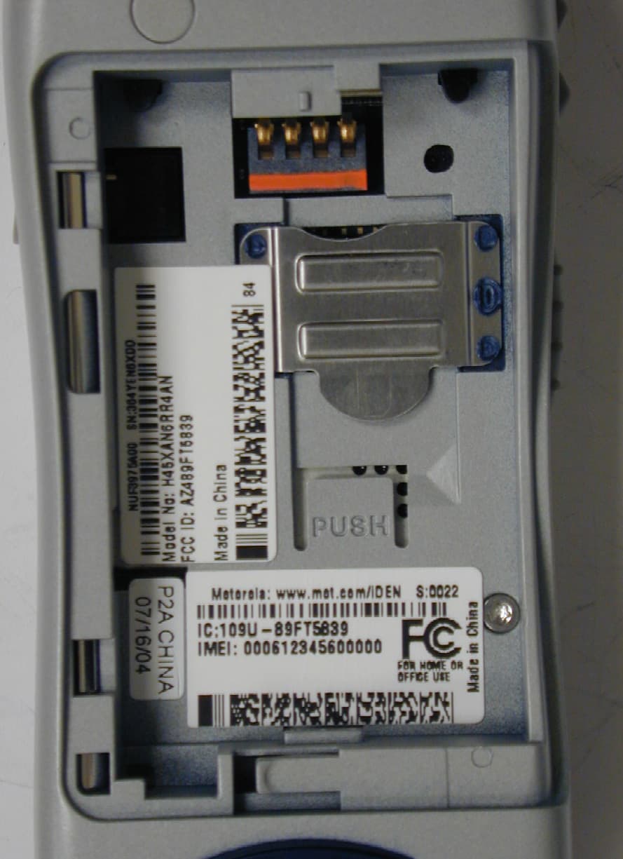
Click to zoom
Application Details
- Equipment Class
- TNE - Licensed Non-Broadcast Transmitter Held to Ear
- Date of Grant
- Aug 29, 2004
- Application Purpose
- Original Equipment
- Date of Application
- Aug 29, 2004
- Equipment Note
- iDEN i265
- Frequency Range
- 896.00000000 - 901.00000000
- Company
- Motorola Solutions, Inc.
- Country
- United States
Documents & Files
Document Text
Text extracted from the exhibit documents filed with the FCC. Open a document above to read the original.
Cover Letter(s)
FCC ID: AZ489FT5839 ______________________________________________________________________________ iDEN, Motorola Inc. 8000 West Sunrise Boulevard, Fort Lauderdale, Florida 33322. CONFIDENTIALITY REQUESTED Date: 26th August 2004 Authorization & Evaluation Division Federal Communications Commission Laboratory 7435 Oakland Mills Road Columbia, MD 21046 Subject: Confidentiality Request for Transmitter with FCC ID: AZ489FT5839. Dear Sir or Madam: Motorola is requesting that Exhibit 4 (Circuit Descriptions), Exhibit 5 (Schematic Diagrams), Exhibit 10 (Parts List and Tune Up Procedures), and Exhibit 12 (Operational Description) not be made routinely available for public inspection. Motorola considers the information in these exhibits to be classified as trade secrets, pursuant to 47 CFR Section 0.457(d) and Section 552(b)(4) of the Freedom of Information Act. We are also requesting that the FCC mark Exhibit 3 (External Photos) and Exhibit 9, (Internal Photos) as Temporary Confidentiality as outlined in Public Notice DA 04-1705, dated June 15, 2004. This provision will give Motorola temporary confidentiality prior to product launch. Please mark Exhibits 4, 5, 10, and 12 as “Confidential” And Exhibit 3 and 9 as “Temporary Confidential”. Please contact me if you require any additional information. Sincerely, /s/ Mike Ramnath (signed) Manager, Regulatory Compliance Tel: (954) 723-5793 E-mail: [email protected] EXHIBIT 13B
External Photos
FCC Filing Package for Motorola i265 Transceiver FCC ID: AZ489FT5839 IDEN, Motorola Inc., 8000 W. Sunrise Blvd., Plantation, FL 33322, USA WWW.MOT.COM/iDEN Page: 3 - 1 Exhibit 3. External Photographs -- Pursuant to 47 CFR 2.1033(c) 12 The radio product shapes, colors and housing vary. Photograph 3-1: Front view, antenna retracted. Photograph 3-2: Back view, antenna retracted, battery cover attached. FCC Filing Package for Motorola i265 Transceiver FCC ID: AZ489FT5839 IDEN, Motorola Inc., 8000 W. Sunrise Blvd., Plantation, FL 33322, USA WWW.MOT.COM/iDEN Page: 3 - 2 Photograph 3-3: Front view, antenna extended. Photograph 3-4: Back view, antenna extended battery cover attached. FCC Filing Package for Motorola i265 Transceiver FCC ID: AZ489FT5839 IDEN, Motorola Inc., 8000 W. Sunrise Blvd., Plantation, FL 33322, USA WWW.MOT.COM/iDEN Page: 3 - 3 Photograph 3-5: Button side view, antenna retracted. Photograph 3-6: Antenna side view, antenna retracted. FCC Filing Package for Motorola i265 Transceiver FCC ID: AZ489FT5839 IDEN, Motorola Inc., 8000 W. Sunrise Blvd., Plantation, FL 33322, USA WWW.MOT.COM/iDEN Page: 3 - 4 Photograph 3-7: Button side view, antenna extended. Photograph 3-8: Antenna side view, antenna extended. FCC Filing Package for Motorola i265 Transceiver FCC ID: AZ489FT5839 IDEN, Motorola Inc., 8000 W. Sunrise Blvd., Plantation, FL 33322, USA WWW.MOT.COM/iDEN Page: 3 - 5 Photograph 3.9: Location of label on back of unit’s housing (battery cover removed). Photograph 3.10: Zoom view of labels containing FCC ID and FCC Logo.
ID Label/Location Info
FCC Filing Package for Motorola i265Transceiver FCC ID: AZ489FT5839 IDEN, Motorola Inc., 8000 W. Sunrise Blvd., Plantation, FL 33322, USA WWW.MOT.COM/iDEN Page 1-2 Exhibit 1. Identification Label -- Pursuant to 47 CFR 2.925, 2.1065 and 2.1033(c) 11 1.1 Location Back side of the radio product unit chassis (Photograph 1.1). 1.2 Type The label is a white polyester film laminate with a pressure sensitive adhesive backing. The adhesive is a permanent type acrylic with minimum peel strength of 5 lbs/in. 1.3 Markings (Text) Enlarged view of label (showing FCC ID and manufacturer type number): Photograph 1.1: Location of label on back of unit’s housing (battery cover removed). FCC Filing Package for Motorola i265Transceiver FCC ID: AZ489FT5839 IDEN, Motorola Inc., 8000 W. Sunrise Blvd., Plantation, FL 33322, USA WWW.MOT.COM/iDEN Page 2-2 Photograph 1.2: Zoom view of labels containing FCC ID and FCC Logo FCC Filing Package for Motorola i265Transceiver FCC ID: AZ489FT5839 IDEN, Motorola Inc., 8000 W. Sunrise Blvd., Plantation, FL 33322, USA WWW.MOT.COM/iDEN Page 2-2 Exhibit 1A. General Information 1A.1 Production Plans Quantity production is planned. 1A.2 Application References -- Pursuant to 47 CFR 2.948 and 2.1061 Reference is made to the following Motorola "Application References" 1. Open Area Test Site “OATS” (FCC Registration: 95517 and 98377 / Industry of Canada: 2056-A) 1A.3 Data Submittal Procedure Data located in Exhibit 6 is supplied in accordance with 47CFR2, Sub-part J and Part 90, Sub-parts I and Sub-part S of the Commission’s rules. 1A.4 Similar, currently Certified Transceiver FCC ID: AZ489FT5822 1A.5 Additional Considerations This radio product also integrates a receiver that will receive and process signals from Global Positioning System satellites. The radio product can also function as a Part 15.3(r) computer peripheral device when functioning as an RF modem when connected to a computer via a data cable accessory (Exhibit 12). A Declaration of Conformity in accordance with 47CFR2.1077(a) is provided in Exhibit 8 as evidence of compliance with Part 15 requirements for these additional Class B digital device functionalities per 47CFR15.101(a). Compliance with Part 15 requirements for the Direct-Conversion (zero IF superheterodyne) receiver has been determined by verification in accordance with 47CFR15.1.
Internal Photos
FCC Filing Package for Motorola i265 Transceiver FCC ID: AZ489FT5839 IDEN, Motorola Inc., 8000 W. Sunrise Blvd., Plantation, FL 33322, USA WWW.MOT.COM/iDEN Page: 9- 1 Exhibit 9. Internal Photographs -- Pursuant to 47 CFR 2.1033(c) 12 Photograph 9-1: Back side view of radio PCB. Photograph 9.3: Back side view of radio PCB without shields. Photograph 9-2: Front side view of radio PCB. Photograph 9.4: Front side view of radio PCB without shields.
RF Exposure Info
CGISS EME Form-SAR-Rpt-Rev. 3.00 Page 1 of 47 CGISS EME Test Laboratory 8000 West Sunrise Blvd Fort Lauderdale, FL. 33322 S.A.R. EME Compliance Test Report Part 2 of 2 Note: Based on the information and the testing results provided herein, the undersigned certifies that when used as stated in the operating instructions supplied, said product complies with the national and international reference standards and guidelines listed in section 2.0 of this report. Jim Fortier’s Signature on file for Ken Enger 8/20/04 ____________________________________________________________ _________________________ Ken Enger Date Approved Senior Resource Manager, Laboratory Director, CGISS EME Lab Note: This report shall not be reproduced without written approval from an officially designated representative of the Motorola EME Laboratory. Certificate Number: 1449-01 Date of Report: August 20, 2004 Report Revision: Rev. O Manufacturer: Motorola Product Description: iDEN i265; 1:6, 1:3, 81:120, 1:12 TDMA; 64 QAM, 16 QAM & QPSK Modulation; 0.6 W Pulse average FCC ID: AZ489FT5839 Device Model: H45XAN6RR4AN/NUF3975A00 Test Period: 8/2/04-8/12/04 Technician: Clint Miller (EME Technician Electronics II) Responsible Eng: Jim Fortier (Elect. Principle Staff Eng.) Author: Michael Sailsman (Global EME Regulatory Affairs Liaison) CGISS EME Form-SAR-Rpt-Rev. 3.00 Page 2 of 47 APPENDIX A Power Slump Data/Shortened Scan CGISS EME Form-SAR-Rpt-Rev. 3.00 Page 3 of 47 DUT Power versus time data CGISS EME Form-SAR-Rpt-Rev. 3.00 Page 4 of 47 Shortened Scan Results FCC ID: AZ489FT5839; Test Date: 8/12/04 Motorola CGISS EME Laboratory Run #: CM-Ab-R3-040812-05 Model #: H45XAN6RR4AN/NUF3975A SN: 364YEN7JB8 TX Freq: 824.9875 MHz Sim Tissue Temp: 18.9 (Celsius) Start Power: 0.609 W Antenna: In Battery Kit: SNN5704C w/ NNTN5845A back cover Carry Acc: NNTN5821A Audio/Data Acc.: NONE Shortened scan reflect highest S.A.R. producing configuration; Run time 11minutes. Representative “normal” scan run time was 24 minutes “Shortened” scan max calculated S.A.R. using S.A.R. drift: 1-g Avg. = 1.38mW/g; 10-g Avg. = 1.01mW/g “Normal” scan max calculated S.A.R. using S.A.R. drift: 1-g Avg. = 1.29mW/g; 10-g Avg. = 0.94mW/g (see section 7.1 run # CM-Ab-R3-040812-04) DUT w/ body worn accessory against phantom Flat Phantom; Section; Position: (90°,90°); Probe: ET3DV6 - SN1383(Cal Date 25 Feb 2004); ConvF(5.82,5.82,5.82); Probe cal date: 25/2/04; Crest factor: 1.5; FCC Body 813: σ = 0.96 mho/m εr = 54.4 ρ = 1.00 g/cm3; DAE3: 401V1 DAE Cal Date: 08/21/2003 Cube 5x5x7: SAR (1g): 1.17 mW/g, SAR (10g): 0.858 mW/g, (Worst-case extrapolation) Cube 5x5x7: Dx = 8.0, Dy = 8.0, Dz = 5.0; SAR (1g): 1.17 mW/g, SAR (10g): 0.858 mW/g Power Drift: -0.49 dB CGISS EME Form-SAR-Rpt-Rev. 3.00 Page 5 of 47 APPENDIX B Data Results CGISS EME Form-SAR-Rpt-Rev. 3.00 Page 6 of 47 FCC ID: AZ489FT5839; Test Date: 8/5/04 Motorola CGISS EME Laboratory Run #: JF-LEAR-R3-040805-02 Model #: H45XAN6RR4AN/NUF3975A SN: 364YEN7JB8 TX Freq: 824.9875 MHz Sim Tissue Temp: 19.1 (Celsius) Start Power: 0.643 W Antenna: In Battery Kit: SNN5705B w/ NNTN5845A back cover Carry Acc: NONE Audio/Data Acc.: NONE DUT at Left ear in cheek touch position SAM; Left Hand Section; Position: (90°,59°); Probe: ET3DV6 - SN1383(Cal Date 25 Feb 2004); ConvF(6.30,6.30,6.30); Probe cal date: 25/2/04; Crest factor: 3.0; IEEE Head 813 MHz: σ = 0.93 mho/m εr = 42.1 ρ = 1.00 g/cm3; DAE3: 401V1 DAE Cal Date: 08/21/2003 Cube 7x7x7: SAR (1g): 1.14 mW/g, SAR (10g): 0.787 mW/g, (Worst-case extrapolation) Coarse: Dx = 15.0, Dy = 15.0, Dz = 10.0; Max at 81.0, 24.0, 4.7 Power Drift: -0.08 dB CGISS EME Form-SAR-Rpt-Rev. 3.00 Page 7 of 47 FCC ID: AZ489FT5839; Test Date: 8/5/04 Motorola CGISS EME Laboratory Run #: CM-FACE-R3-040805-15 Model #: H45XAN6RR4AN/NUF3975A SN: 364YEN7JB8 TX Freq: 813.5125 MHz Sim Tissue Temp: 18.9 (Celsius) Start Power: 0.654 W Antenna: In Battery Kit: SNN5705B w/ NNTN5845A back cover Carry Acc: NONE Audio/Data Acc.: NONE DUT front separated 2.5cm from phantom SAM - Expanded Phantom; Flat Section; Position: (90°,90°); Probe: ET3DV6 - SN1383(Cal Date 25 Feb 2004); ConvF(6.30,6.30,6.30); Probe cal date: 25/2/04; Crest factor: 6.0; IEEE Head 813 MHz: σ = 0.93 mho/m εr = 42.1 ρ = 1.00 g/cm3; DAE3: 401V1 DAE Cal Date: 08/21/2003 Cube 7x7x7: SAR (1g): 0.146 mW/g, SAR (10g): 0.105 mW/g, (Worst-case extrapolation) Coarse: Dx = 15.0, Dy = 15.0, Dz = 10.0; Max at 27.0, 78.0, 4.7 Power drift: 0.05 dB CGISS EME Form-SAR-Rpt-Rev. 3.00 Page 8 of 47 FCC ID: AZ489FT5839; Test Date: 8/4/04 Motorola CGISS EME Laboratory Run #: CM-LEAR-R3-040804-23 Model #: H45XAN6RR4AN/NUF3975A SN: 364YEN7JB8 TX Freq: 896.01875 MHz Sim Tissue Temp: 19.3 (Celsius) Start Power: 0.623 W Antenna: In Battery Kit: SNN5705B w/ NNTN5845A back cover Carry Acc: NONE Audio/Data Acc.: NONE DUT at Left ear in cheek touch position SAM; Left Hand Section; Position: (90°,59°); Probe: ET3DV6 - SN1383(Cal Date 25 Feb 2004); ConvF(6.30,6.30,6.30); Probe cal date: 25/2/04; Crest factor: 3.0; IEEE Head 899 MHz: σ = 1.00 mho/m εr = 40.8 ρ = 1.00 g/cm3; DAE3: 401V1 DAE Cal Date: 08/21/2003 Cube 7x7x7: SAR (1g): 0.957 mW/g, SAR (10g): 0.653 mW/g * Max outside, (Worst-case extrapolation) Coarse: Dx = 15.0, Dy = 15.0, Dz = 10.0; Max at 78.0, 28.5, 4.7 Power drift: 0.00 dB Note: “Max outside” has been identified by SPEAG as an unresolved intermittent occurrence with the DASY 3 application even when the entire peak area is captured. CGISS EME Form-SAR-Rpt-Rev. 3.00 Page 9 of 47 FCC ID: AZ489FT5839; Test Date: 8/5/04 Motorola CGISS EME Laboratory Run #: CM-FACE-R3-040805-16 Model #: H45XAN6RR4AN/NUF3975A SN: 364YEN7JB8 TX Freq: 896.01875 MHz Sim Tissue Temp: 18.9 (Celsius) Start Power: 0.635 W Antenna: In Battery Kit: SNN5705B w/ NNTN5845A back cover Carry Acc: NONE Audio/Data Acc.: NONE DUT front separated 2.5cm from phantom SAM - Expanded Phantom; Flat Section; Position SAM - Expanded Phantom; Flat Section; Position: (90°,90°); Probe: ET3DV6 - SN1383(Cal Date 2…
Text truncated - open the document above for the full version.
RF Exposure Info
CGISS EME Form-SAR-Rpt-Rev. 3.00 Page 1 of 25 CGISS EME Test Laboratory 8000 West Sunrise Blvd Fort Lauderdale, FL. 33322 S.A.R. EME Compliance Test Report Part 1 of 2 Note: Based on the information and the testing results provided herein, the undersigned certifies that when used as stated in the operating instructions supplied, said product complies with the national and international reference standards and guidelines listed in section 2.0 of this report. Jim Fortier’s signature on file for Ken Enger 8/20/04 ____________________________________________________________ _________________________ Ken Enger Date Approved Senior Resource Manager, Laboratory Director, CGISS EME Lab Note: This report shall not be reproduced without written approval from an officially designated representative of the Motorola EME Laboratory. Date of Report: August 20, 2004 Report Revision: Rev. O Manufacturer: Motorola Product Description: iDEN i265; 1:6, 1:3, 81:120, 1:12 TDMA; 64 QAM, 16 QAM & QPSK Modulation; 0.6 W Pulse average FCC ID: AZ489FT5839 Device Model: H45XAN6RR4AN/NUF3975A00 Certificate Number: 1449-01 Test Period: 8/2/04-8/12/04 Technician: Clint Miller (EME Technician Electronics II) Responsible Eng: Jim Fortier (Elect. Principle Staff Eng.) Author: Michael Sailsman (Global EME Regulatory Affairs Liaison) CGISS EME Form-SAR-Rpt-Rev. 3.00 Page 2 of 25 TABLE OF CONTENTS Part 1 of 2 1.0 Introduction 2.0 Reference Standards and Guidelines 3.0 Description of Test Sample 3.1 Test Signal 3.2 Test Output Power 4.0 Description of Test Equipment 4.1 Description of S.A.R Measurement System 4.2 Description of Phantom 4.2.1 Flat Phantom 4.2.2 SAM phantom 4.3 Simulated Tissue Properties 4.3.1 Type of Simulated Tissue 4.3.2 Simulated Tissue Composition 4.4 Test conditions 5.0 Probe Scan Procedures 5.1 Shortened scan rationale 5.2 Description of Test Procedure 5.3 Device Test Positions 5.3.1 Body 5.3.2 Head 5.3.3 Face 5.4 Test Position Photographs 6.0 Measurement Uncertainty 7.0 S.A.R. Test Results 7.1 S.A.R. results 7.2 Peak S.A.R. location 7.3 Highest S.A.R. results calculation methodology 8.0 Conclusion Part 2 of 2 Appendix A: Power Slump Data/Shortened scan Appendix B: Data Results Appendix C: Dipole System Performance Check Results Appendix D: Probe/Dipole Calibration Certificates Appendix E: Illustration of Body-worn Accessories Appendix F: Accessories and options test status and separation distances CGISS EME Form-SAR-Rpt-Rev. 3.00 Page 3 of 25 REVISION HISTORY Date Revision Comments 8/20/04 O Release of Prototype results CGISS EME Form-SAR-Rpt-Rev. 3.00 Page 4 of 25 1.0 Introduction This report details the utilization, test setup, test equipment, and test results of the Specific Absorption Rate (S.A.R.) measurements performed at the CGISS EME Test Lab for model number H45XAN6RR4AN/NUF3975A00, FCC ID: AZ489FT5839. The applicable exposure environment is General Population/Uncontrolled. 2.0 Reference Standards and Guidelines This product is designed to comply with the following national and international standards and guidelines. • United States Federal Communications Commission, Code of Federal Regulations; 47CFR part 2 sub-part J • IEEE 1528, 2003 "Recommended Practice for Determining the Peak Spatial-Average Specific Absorption Rate (SAR) in the Human Head from Wireless Communications Devices: Measurement Techniques" • American National Standards Institute (ANSI) / Institute of Electrical and Electronic Engi- neers (IEEE) C95. 1-1992 • Institute of Electrical and Electronic Engineers (IEEE) C95.1-1999 Edition • International Commission on Non-Ionizing Radiation Protection (ICNIRP) 1998 • Ministry of Health (Canada) Safety Code 6. Limits of Human Exposure to Terminal frequency Electromagnetic Fields in the Frequency Range from 3 kHz to 300 GHz, 1999 • Australian Communications Authority Radiocommunications (Electromagnetic Radiation - Human Exposure) Standard 2003 • ANATEL, Brazil Regulatory Authority, Resolution No. 303 of July 2, 2002 "Regulation of the limitation of exposure to electrical, magnetic, and electromagnetic fields in the radio frequency range between 9KHz and 300 GHz." and “Attachment to resolution # 303 from July 2, 2002” CGISS EME Form-SAR-Rpt-Rev. 3.00 Page 5 of 25 3.0 Description of Test Sample (Horizontal and vertical reference lines intersecting at the acoustic output are marked in white on the DUT) FCC ID: AZ489FT5839 is a digital multi-service data capable device that employs time division multiplexing transmission technology with a duty cycle ranging from 16.67% to 33.33% using M16- QAM modulation for voice or circuit data transmission. There is a Split 1:3 mode that operates using a 16.67% transmission duty cycle. Two 7.5ms pulses occur during the six time slots within the 90-msec frame format. This mode is available in both the 806-825MHz and 896-902MHz bands in the telephone interconnect mode only. Packet data transmission is also supported up to a maximum duty cycle of 67.5% using quad QPSK modulation. This device will be marketed to and used by the general population. This device may be used while held against the head in voice mode, in front of the face in PTT mode, and against the body in voice, PTT and data modes. FCC ID: AZ489FT5839 is capable of operating in the 806-825 MHz and 896-902MHz bands. Packet data transmission is not available while transmitting in the 896-902 MHz band. The rated power is 0.60 watts pulsed averaged. The maximum output is 0.64 watts pulsed average as defined by the upper limit of the production line final test station. CGISS EME Form-SAR-Rpt-Rev. 3.00 Page 6 of 25 FCC ID: AZ489FT5839 is offered with the following options and accessories: Antenna Description 8585924E01 806 – 941 MHz ½ wave retractable antenna; 10.6cm Worst case antenna gain –0.94dBd @ 813MHz, 0.86dBd @ 896 MHz Batteries SNN5705B 750mAh Lithium Ion battery SNN5704A 700mAh Slim line Lithium Ion battery SNN5705C 8-mm battery (950 mAh) SNN5704C 700mAh Slim line Lithium Ion battery N…
Text truncated - open the document above for the full version.
Test Report
FCC Filing Package for Motorola i265 Transceiver FCC ID: AZ489FT5839 IDEN, Motorola Inc., 8000 W. Sunrise Blvd., Plantation, FL 33322, USA WWW.MOT.COM/iDEN Page: 6- 21 6.4. Radiated Spurious Emissions -- Pursuant 47 CFR 2.1053, 2.1057, 90.210(g) (3), 90.691(a) (2) FCC Limits -Per 90.210(g) (3) and 90.691(a) (2), radiated spurious emissions shall be attenuated below the maximum level of emission of the carrier frequency in accordance with the following formula: Spurious attenuation in dB = 43 + 10 log 10 (P) (Thus the effective limit is -13 dBm for any transmitter power level). NOTE 1: Spurious emissions are dependent on the linearity of the Power Amplifier (U516) and are independent of modulation type or TDM interleaving. Thus emissions were tested with the radio set to Quad-16QAM at both maximum and minimum radio output power settings. Data is presented for both primary source and alternate source Power Amplifier (U516). NOTE 2: An asterisk (*) in the data indicates the spurious emission was less than -33 dBm or could not be detected due to noise limitations or ambients. NOTE 3: Spurious emission levels were measured with the non-detachable antenna mounted on the radio product, as in intended use. Measurement setup is described in Exhibit 7.3. FCC Filing Package for Motorola i265 Transceiver FCC ID: AZ489FT5839 IDEN, Motorola Inc., 8000 W. Sunrise Blvd., Plantation, FL 33322, USA WWW.MOT.COM/iDEN Page: 6- 22 Motorola Inc. i265 806.0625 MHz SpurFrequency (MHz) FCC Maximum Limit -13 (dBm) 25 kHz Ch. Spac. Horizontal Measured Emission Equiv. Pwr Into Ideal Dipole (dBm) Vertical Measured Emission Equiv Pwr Into Ideal Dipole (dBm) -13 -13 -13 -13 2XFund1612.1250-13** 3XFund 2418.1875-13-38.10* 4XFund 3224.2500-13** 5XFund 4030.3125-13** 6XFund 4836.3750-13** 7XFund 5642.4375-13** 8XFund 6448.5000-13** 9XFund 7254.5625-13** 10XFund8060.6250-13** * Indicates the spurious emission could not be detected due to noise limitations or ambients. i265 813.5625 MHz SpurFrequency (MHz) FCC Maximum Limit -13 (dBm) 25 kHz Ch. Spac. Horizontal Measured Emission Equiv. Pwr Into Ideal Dipole (dBm) Vertical Measured Emission Equiv Pwr Into Ideal Dipole (dBm) -13 -13 -13 -13 2XFund1627.1250-13** 3XFund 2440.6875-13** 4XFund 3254.2500-13** 5XFund 4067.8125-13** 6XFund 4881.3750-13** 7XFund5694.9375-13** 8XFund 6508.5000-13** 9XFund 7322.0625-13** 10XFund8135.6250-13** * Indicates the spurious emission could not be detected due to noise limitations or ambients. The data presented here was taken using the substitution method as found in the TIA/EIA-603 document. Motorola Plantation EMC Lab – Test Performed by: Frank Baader FCC Registration: 91932 / Industry Canada: IC3679 FCC ID:AZ489FT5839 Transmitter Radiated Spurious Emissions: Transmitter Radiated Spurious Emissions: August 11, 2004 Channel Spacing 25KHZ S/N 364YEN7HTN Channel Spacing 25KHZ S/N 364YEN7HTN Radiated Spurious Emissions -33 -28 -23 -18 -13 -8 -3 2 1 6 1 2 . 1 2 5 0 2 4 1 8 . 1 8 7 5 3 2 2 4 . 2 5 0 0 4 0 3 0 . 3 1 2 5 4 8 3 6 . 3 7 5 0 5 6 4 2 . 4 3 7 5 6 4 4 8 . 5 0 0 0 7 2 5 4 . 5 6 2 5 8 0 6 0 . 6 2 5 0 Frequency (MHz) Emission Level dBm Horizontal Measured Emission Equiv. Pwr Into Ideal Dipole (dBm) Vertical Measured Emission Equiv Pwr Into Ideal Dipole (dBm) FCC Maximum Limit -13 (dBm) 25 kHz Ch. Spac. Radiated Spurious Emissions -33 -28 -23 -18 -13 -8 -3 2 1 6 2 7 . 1 2 5 0 2 4 4 0 . 6 8 7 5 3 2 5 4 . 2 5 0 0 4 0 6 7 . 8 1 2 5 4 8 8 1 . 3 7 5 0 5 6 9 4 . 9 3 7 5 6 5 0 8 . 5 0 0 0 7 3 2 2 . 0 6 2 5 8 1 3 5 . 6 2 5 0 Frequency (MHz) Emission Level dBm Horizontal Measured Emission Equiv. Pwr Into Ideal Dipole (dBm) Vertical Measured Emission Equiv Pwr Into Ideal Dipole (dBm) FCC Maximum Limit -13 (dBm) 25 kHz Ch. Spac. Figure 6-23a: Maximum Power Setting Transmitter Spurious Emissions FCC Filing Package for Motorola i265 Transceiver FCC ID: AZ489FT5839 IDEN, Motorola Inc., 8000 W. Sunrise Blvd., Plantation, FL 33322, USA WWW.MOT.COM/iDEN Page: 6- 23 Motorola Inc. i265 820.9875 MHz SpurFrequency (MHz) FCC Maximum Limit -13 (dBm) 25 kHz Ch. Spac. Horizontal Measured Emission Equiv. Pwr Into Ideal Dipole (dBm) Vertical Measured Emission Equiv Pwr Into Ideal Dipole (dBm) - 13 -13 -13 -13 2XFund 1641.9750-13 ** 3XFund 2462.9625-13** 4XFund 3283.9500-13** 5XFund 4104.9375-13** 6XFund 4925.9250-13** 7XFund5746.9125-13** 8XFund 6567.9000-13** 9XFund 7388.8875-13** 10XFund8209.8750-13** * Indicates the spurious emission could not be detected due to noise limitations or ambients. i265 824.9875 MHz SpurFrequency (MHz) FCC Maximum Limit -13 (dBm) 25 kHz Ch. Spac. Horizontal Measured Emission Equiv. Pwr Into Ideal Dipole (dBm) Vertical Measured Emission Equiv Pwr Into Ideal Dipole (dBm) - 13 -13 -13 -13 2XFund 1649.9750-13 ** 3XFund 2474.9625-13** 4XFund 3299.9500-13** 5XFund4124.9375-13** 6XFund 4949.9250-13** 7XFund 5774.9125-13** 8XFund 6599.9000-13** 9XFund 7424.8875-13** 10XFund8249.8750-13** * Indicates the spurious emission could not be detected due to noise limitations or ambients. The data presented here was taken using the substitution method as found in the TIA/EIA-603 document. Motorola Plantation EMC Lab – Test Performed by: Frank Baader FCC Registration: 91932 / Industry Canada: IC3679 Channel Spacing 25KHZ S/N 364YEN7HTN FCC ID:AZ489FT5839 August 11, 2004 Transmitter Radiated Spurious Emissions: Transmitter Radiated Spurious Emissions: Channel Spacing 25KHZ S/N 364YEN7HTN Radiated Spurious Emissions -33 -28 -23 -18 -13 -8 -3 2 1 6 4 1 . 9 7 5 0 2 4 6 2 . 9 6 2 5 3 2 8 3 . 9 5 0 0 4 1 0 4 . 9 3 7 5 4 9 2 5 . 9 2 5 0 5 7 4 6 . 9 1 2 5 6 5 6 7 . 9 0 0 0 7 3 8 8 . 8 8 7 5 8 2 0 9 . 8 7 5 0 Frequency (MHz) Emission Level dBm Horizontal Measured Emission Equiv. Pwr Into Ideal Dipole (dBm) Vertical Measured Emission Equiv Pwr Into Ideal Dipole (dBm) FCC Maximum Limit -13 (dBm) 25 kHz Ch. Spac. Radiated Spurious Emissions -33 -28 -23 -18 -13 -8 -3 2 1 6 4 9 . 9 7 5 0 2 4 7 4 . 9 6 2 5 3 2 9 9 . 9 5 0 0 4 1 2 4 . 9 3 7 5 4 9 4 9 . 9 2 5 0 5 7 7 4 . 9…
Text truncated - open the document above for the full version.
Test Report
FCC Filing Package for Motorola i265 Transceiver FCC ID: AZ489FT5839 IDEN, Motorola Inc., 8000 W. Sunrise Blvd., Plantation, FL 33322, USA WWW.MOT.COM/iDEN Page: 6- 1 Exhibit 6. Measured Data -- Pursuant 47 CFR. 2.1041 6.1 Transmitter Power The transmitter is a variable power type used in a SMR trunking system. Output power (as defined in 47 CFR 90.7) is dynamically controlled as described in Exhibit 12. 6.1.1 Maximum Output Power Rating -- Pursuant 47 CFR 2.1033(c) 7 and 90.635(d)) Maximum output power rating: 640 milliwatts (28.06 dBm), pulse average power Note 1: Nominal output power rating: 600 milliwatts (27.78 dBm) (Pulse average power). Note 2: These ratings are compliant with the FCC maximum of 100 watts (50 dBm) for Mobile stations Note 3: The term pulse average power is used to specify the power that would be measured during the intervals of recurrent TDM transmission pulses by an average responding RF power meter. Power expressed in this manner is independent of the TDM duty cycle, and facilitates RF system coverage analysis. 6.1.2 Operating output power range -- Pursuant 47 CFR 2.1033(c) 6) Maximum tuned output power will vary over a range of 640 to 500 milliwatts (maximum plus average power) to a minimum power of 39 dB below maximum tuned output power. 6.1.3 DC power used by final amplifier device -- Pursuant 47 CFR 2.1033(c) 8) In order to prevent the malfunctions that can occur due to directly measuring the DC characteristics of the final RF amplifying stage, data was obtained by measuring the entire radio DC current and is reported herein for the entire radio. The DC current and the RF output power was measured with a special RF/DC test fixture set to supply the radio with the nominal battery voltage of 4.0 V. The characteristics were measured during a transmission pulse and are listed in the Table 6-1. 800 MHz band 900 MHz band Characteristics At the maximum power setting At the minimum power setting At the maximum power setting At the minimum power setting DC Voltage (Volts) 4 4 4 4 DC Current (A) 1.422 0.656 1.219 0.64 Output Power (mW) 588 0.07 610 0.07 Table 6-1 Characteristics for 800 and 900 MHz bands
Test Report
FCC Filing Package for Motorola i265 Transceiver FCC ID: AZ489FT5839 IDEN, Motorola Inc., 8000 W. Sunrise Blvd., Plantation, FL 33322, USA WWW.MOT.COM/iDEN Page: 6- 3 6.2 Modulation Characteristics and Necessary Bandwidth -- Pursuant 47 CFR 2.1033(c) 13, 2.1047(d) & 2.202 Digitally encoded speech or digital data is transmitted in four sub-channels at a 4 kHz rate using M-ary symbols mapped to predetermined fixed magnitude and phase components within 1 of 3 constellations associated with a particular modulation scheme. Figure 6-2 illustrates symbol mapping to one of the four QPSK sub-channels constellations. Figure 6-3 illustrates symbol mapping to one of the four-16QAM sub-channels constellation. Figure 6-4 illustrates symbol mapping to one of the four-64QAM sub-channels constellation. For Quad-QPSK modulation, this mapping adjusts the amplitude and phase variations of the baseband signal to one of 4 points on the constellation. For Quad- 16QAM modulation, this mapping adjusts the amplitude and phase variations of the baseband signal to one of 16 points on the constellation. For Quad-64 modulation, this mapping adjusts the amplitude and phase variations of the baseband signal to one of 64 points on the constellation. The bandwidth of the modulating signals is limited by the pair of modulation limiting low pass filters within the modem block function of U801 (see Figure 4-2 in Exhibit 4.3). These filters serve to limit out-of-band and spurious emissions due to modulation. The necessary bandwidth of the sub-channels is limited to 4.8 kHz by the pair of modulation limiting low pass filters. The transfer response of these filters is depicted in Figure 6-1 where the filter excess bandwidth coefficient of 0.2 is shown. This excess bandwidth leads to the necessary bandwidth calculation of (1 + 0.2) x (4 kHz) = 4.8 kHz. Since the sub-channels are spaced 4.5 kHz apart, the necessary bandwidth of the composite 4 sub-channel symbol streams is 4.8 + (3 x 4.5) = 18.3 kHz. FCC Filing Package for Motorola i265 Transceiver FCC ID: AZ489FT5839 IDEN, Motorola Inc., 8000 W. Sunrise Blvd., Plantation, FL 33322, USA WWW.MOT.COM/iDEN Page: 6- 4 0.707 02k2.4k-2k H(f)=root raised α =0.2 Modulation Low Pass Filter Res ponse ω o ω where ω o = 2000 and ω = (1+ α ) ω o = 2400Hz 1for |f| <2 ω o - ω cos 2 ( π /4 (|f| + ω - 2 ω o )/( ω - ω o ))for 2 ω o - ω < |f|< ω 0for |f| > ω { H(f)= Figure 6-1: Modulation Low Pass Filter Response x jy +1+3-1-3 +1 +3 -3 -1 θ Symbol Mapping onto One of Four QPSK Constellations QAM baseband output ready for impression onto a particular subcarrier. Data Source QPSK Encoder Interleaver Subchannel Formatter Modem Interface Bit Stream Complex Symbol Stream Figure 6-2: Symbol Mapping onto One of Four QPSK Constellations FCC Filing Package for Motorola i265 Transceiver FCC ID: AZ489FT5839 IDEN, Motorola Inc., 8000 W. Sunrise Blvd., Plantation, FL 33322, USA WWW.MOT.COM/iDEN Page: 6- 5 x jy +1+3-1-3 +1 +3 -3 -1 θ Symbol Mapping onto One of Four 16-QAM Constellations QAM baseband output ready for impression onto a particular subcarrier. Data Source 16QAM Encoder Real to Complex Combiner Interleaver Modem Interface Bit Stream Complex Symbol Stream Subchannel Formatter Real Symbol Stream Figure 6-3: Symbol Mapping onto One of Four 16-QAM Constellations x jy +.5 +3.5-.5-3.5 +.5 +3.5 -3 .5 -.5 θ Symbol Mapping onto One of Four 64-QAM Constellations QAM baseband output ready for impression onto a particular subcarrier. Data Source 16QAM Encoder Real to Complex Combiner Interleaver Modem Interface Bit Stream Complex Symbol Stream Subchannel Formatter Real Symbol Stream 0 1 -2.0 +2.0 .5 + Figure 6-4: Symbol Mapping onto One of Four 64-QAM Constellations FCC Filing Package for Motorola i265 Transceiver FCC ID: AZ489FT5839 IDEN, Motorola Inc., 8000 W. Sunrise Blvd., Plantation, FL 33322, USA WWW.MOT.COM/iDEN Page: 6- 6 6.3 Emission Mask -- Pursuant 47 CFR 2.1049(h) & 90.210(m) The method described in paragraph 7.2 was employed with the following conditions: For Quad-QPSK Modulation…
Text truncated - open the document above for the full version.
Contact Information
Applicant
Arine Lee(Certification Manager)
Test Firm
MotorolaWilliam Elliott
Technical Specifications
| # | Rule Parts | Frequency Range | Power Output | Emission | Tolerance |
|---|---|---|---|---|---|
| 2 | 9 | 896 MHz - 901 MHz | 640.00 mW | 18K3D7W | 0.5 ppm |
Other Applications from Motorola Solutions, Inc.

AZ489FT4980
Sep 08, 2026Portable two way radio
Equipment Class
TNF - Licensed Non-Broadcast Transmitter Held to FaceAZ489FT4981
Aug 14, 2026Handheld Portable - TANAPA BPR 45 400-470 MHZ 4W NKP
Equipment Class
TNF - Licensed Non-Broadcast Transmitter Held to Face
AZ489FT7187
Jul 13, 2026Portable 2-Way Radio with Bluetooth, Bluetooth LE, WIFI 2.4GHz, WIFI 5GHz, LTE
Equipment Class
DSS - Part 15 Spread Spectrum TransmitterAZ499FT6031
May 11, 2026Operation Critical Wireless Earpiece PTT
Equipment Class
DSS - Part 15 Spread Spectrum Transmitter
AZ499FT5879
Dec 19, 20252-way Portable Radio with BT, BTLE, WIFI, NFC and LTE
Equipment Class
DSS - Part 15 Spread Spectrum Transmitter