AZ489FT5842DTR series Two-Way Portable Transceiver - MOTOtalk
Motorola Solutions, Inc.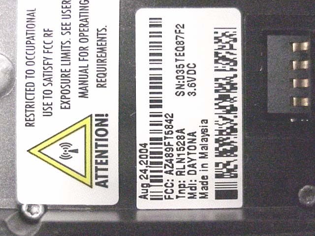
Click to zoom
Application Details
- Equipment Class
- DSS - Part 15 Spread Spectrum Transmitter
- Date of Grant
- Jan 13, 2005
- Application Purpose
- Original Equipment
- Date of Application
- Jan 13, 2005
- Equipment Note
- DTR series Two-Way Portable Transceiver - MOTOtalk
- Frequency Range
- 902.00000000 - 928.00000000
- Company
- Motorola Solutions, Inc.
- Country
- United States
Documents & Files
Document Text
Text extracted from the exhibit documents filed with the FCC. Open a document above to read the original.
Users Manual
Title Page RBR MotoTalk Model Name/Number User Guide Motorola, Inc. 8000 West Sunrise Boulevard Fort Lauderdale, Florida 33322 9980384R89 Product Safety and RF Exposure Compliance ATTENTION! This radio is restricted to occupational use only to satisfy FCC RF energy exposure requirements. Before using this product, read the RF energy awareness information and operating instructions in the Product Safety and RF Exposure booklet enclosed with your radio (Motorola Publication part number 6881095C98) to ensure compliance with RF energy exposure limits. For a list of Motorola-approved antennas, batteries, and other accessories, visit the following web site which lists approved accessories: <http://www.motorola.com/cgiss/index.shtml> Computer Software Copyrights The Motorola products described in this manual may include copyrighted Motorola computer programs stored in semiconductor memories or other media. Laws in the United States and other countries preserve for Motorola certain exclusive rights for copyrighted computer programs, including, but not limited to, the exclusive right to copy or reproduce in any form the copyrighted computer program. Accordingly, any copyrighted Motorola computer programs contained in the Motorola products described in this manual may not be copied, reproduced, modified, reverse-engineered, or distributed in any manner without the express written permission of Motorola. Furthermore, the purchase of Motorola products shall not be deemed to grant either directly or by implication, estoppel, or otherwise, any license under the copyrights, patents or patent applications of Motorola, except for the normal non-exclusive license to use that arises by operation of law in the sale of a product. Document Copyrights No duplication or distribution of this document or any portion thereof shall take place without the express written permission of Motorola. No part of this manual may be reproduced, distributed, or transmitted in any form or by any means, electronic or mechanical, for any purpose without the express written permission of Motorola. Disclaimer The information in this document is carefully examined, and is believed to be entirely reliable. However, no responsibility is assumed for inaccuracies. Furthermore, Motorola reserves the right to make changes to any products herein to improve readability, function, or design. Motorola does not assume any liability arising out of the applications or use of any product or circuit described herein; nor does it cover any license under its patent rights nor the rights of others. Trademarks MOTOROLA, and the Stylized M logo, are registered in the US Patent & Trademark Office. All other product or service names are the property of their respective owners. © Motorola, Inc. 2003. Before using this product, read the operating instructions for safe usage contained in the Product Safety and RF Exposure booklet enclosed with your radio. ! C a u t i o n Table of Contents1 9980384R89 July 23, 2004 Table of Contents Chapter 1Introduction ......................................................................... 1-1 Notations Used in This Manual................................................................................................................... 1 Your RBR MotoTalk Radio ........................................................................................................................ 2 Understanding Your Display....................................................................................................................... 3 Status Indicators......................................................................................................................................... 3 Alert Tones ................................................................................................................................................. 3 Standard Accessories................................................................................................................................. 3 Battery .............................................................................................................................................. 3 Charging Status LEDs ...................................................................................................................... 4 Swivel Belt Holster ............................................................................................................................ 5 Universal Connector Cover............................................................................................................... 5 Chapter 2General Radio Operations.................................................. 2-7 Turning Your Radio On or Off..................................................................................................................... 7 Adjusting the Volume.................................................................................................................................. 7 Using the Radio .......................................................................................................................................... 7 Send a Message ............................................................................................................................... 7 Receiving a Message or Alert ........................................................................................................... 8 Managing Your Messages and Alerts ...............................................................................................8 Access the Main Menu ............................................................................................................................... 9 Recent Calls ..................................................................................................................................... 9 Settings ........................................................................................................................…
Text truncated - open the document above for the full version.
Users Manual
English Product Safety and RF Energy Exposure Booklet for Portable Two-Way Radios The information provided in this document supersedes the general safety information contained in user guides published prior to February 2002. BEFORE USING THIS RADIO, READ THIS BOOKLET WHICH CONTAINS IMPORTANT OPERATING INSTRUCTIONS FOR SAFE USAGE AND RF ENERGY AWARENESS AND CONTROL INFORMATION AND OPERATIONAL INSTRUCTIONS FOR COMPLIANCE WITH RF ENERGY EXPOSURE LIMITS IN APPLICABLE NATIONAL AND INTERNATIONAL STANDARDS. ALSO READ THE OPERATIONAL INSTRUCTIONS FOR SAFE USAGE. FOR RADIOS THAT HAVE BEEN APPROVED AS INTRINSICALLY SAFE, READ THE INSTRUCTIONS AND INFORMATION ON INTRINSIC SAFETY ON PAGE 10 OF THIS BOOKLET. ! C a u t i o n © Motorola, Inc. 2004 8000 W. Sunrise Blvd., Ft. Lauderdale, FL 33322 68P81095C98 68P81095C98-C 95C98-C.book Page 1 Wednesday, October 27, 2004 11:59 AM 2 English RF Energy Exposure Awareness and Control Information and Operational Instructions for Occupational Use NOTICE: This radio is intended for use in occupational/controlled conditions where users have full knowledge of their exposure and can exercise control over their exposure to meet the occupational limits in FCC and International standards. This radio device is NOT authorized for general population consumer use. This two-way radio uses electromagnetic energy in the radio frequency (RF) spectrum to provide communications between two or more users over a distance. It uses radio frequency (RF) energy or radio waves to send and receive calls. RF energy is one form of electromagnetic energy. Other forms include, but are not limited to, sunlight and x-rays. RF energy, however, should not be confused with these other forms of electromagnetic energy, which when used improperly, can cause biological damage. Very high levels of x-rays, for example, can damage tissues and genetic material. Experts in science, engineering, medicine, health, and industry work with organizations to develop standards for safe exposure to RF energy. These standards provide recommended levels of RF exposure for both workers and the general public. These recommended RF exposure levels include substantial margins of protection. All Motorola two-way radios are designed, manufactured, and tested to ensure they meet government-established RF exposure levels. In addition, manufacturers also recommend specific operating instructions to users of two-way radios. These instructions are important because they inform users about RF energy exposure and provide simple procedures on how to control it. 95C98-C.book Page 2 Wednesday, October 27, 2004 11:59 AM 3 English Please refer to the following websites for more information on what RF energy exposure is and how to control your exposure to assure compliance with established RF exposure limits: http://www.fcc.gov/oet/rfsafety/rf-faqs.html http://www.osha.gov/SLTC/radiofrequencyradiation/index.html Federal Communication Commission (FCC) Regulations The FCC rules require manufacturers to comply with the FCC RF energy exposure limits for portable two-way radios before they can be marketed in the U.S. When two-way radios are used as a consequence of employment, the FCC requires users to be fully aware of and able to control their exposure to meet occupational requirements. Exposure awareness can be facilitated by the use of a product label directing users to specific user awareness information. Your Motorola two-way radio has a RF Exposure Product Label. Also, your Motorola user manual, or separate safety booklet includes information and operating instructions required to control your RF exposure and to satisfy compliance requirements. Compliance with RF Exposure Standards Your Motorola two-way radio is designed and tested to comply with a number of national and International standards and guidelines (listed below) for human exposure to radio frequency electromagnetic energy. This radio complies with the IEEE (FCC) and ICNIRP exposure limits for occupational/controlled RF exposure environments at operating duty factors of up to 50% talk-50% listen and is authorized by the FCC for occupational use only. In terms of measuring RF energy for compliance with these exposure guidelines, your radio generates measurable RF energy only while it is transmitting (during talking), not when it is receiving (listening) or in standby mode. NOTE:The approved batteries, supplied with this radio, are rated for a 5-5-90 duty factor (5% talk-5% listen-90% standby) even though this radio complies with FCC occupational exposure limits and may operate at duty factors of up to 50% talk. 95C98-C.book Page 3 Wednesday, October 27, 2004 11:59 AM 4 English Your Motorola two-way radio complies with the following RF energy exposure standards and guidelines: • United States Federal Communications Commission, Code of Federal Regulations; 47CFR part 2 sub-part J • American National Standards Institute (ANSI) / Institute of Electrical and Electronic Engineers (IEEE) C95. 1-1992 • Institute of Electrical and Electronic Engineers (IEEE) C95.1-1999 Edition • International Commission on Non-Ionizing Radiation Protection (ICNIRP) 1998 • Ministry of Health (Canada) Safety Code 6. Limits of Human Exposure to Radiofrequency Electromagnetic Fields in the Frequency Range from 3 kHz to 300 GHz, 1999 • Australian Communications Authority Radiocommunications (Electromagnetic Radiation – Human Exposure) Standard, 2003 • ANATEL ANNEX to Resolution No. 303 of July 2, 2002 "Regulation of limitation of exposure to electrical, magnetic and electromagnetic fields in the radio frequency range between 9 KHz and 300 GHz" and "Attachment to resolution # 303 from July 2, 2002" RF Exposure Compliance and Control Guidelines and Operating Instructions To control your exposure and ensure compliance with the occupational/controlled environment exposure limits, always adhere to the following procedures. Guidelines: • Do not remove the RF Exposure Label from the device. • User awareness i…
Text truncated - open the document above for the full version.
Cover Letter(s)
Applicant: Motorola Inc FCC ID: AZ489FT5842 Motorola Inc., 8000 W. Sunrise Blvd., Plantation, FL 33322 Page: 13- 1 11 th November 2004 Authorization & Evaluation Division Federal Communications Commission Laboratory 7435 Oakland Mills Road Columbia, MD 21046 Gentlemen; Motorola Inc., 8000 West Sunrise Boulevard, Fort Lauderdale, Florida 33322, herein submits its application for Certification of the transmitter with FCC ID: AZ489FT5842. This transmitter operates in the ISM band (902 – 928 MHz). Certification is sought for this transceiver under FCC Rule Part 15c, and performance data is provided for that purpose. This transceiver is frequency hopping spread spectrum operating in the unlicensed ISM (902-928 MHz) band. It uses an FSK (Frequency Shift Key) modulation, 50 kHz spacing up to 1 watt. The protocol is defined to have 10 interleaved hopsets of 50 frequencies each with 500 kHz separation between set members. All 10 hopsets span the entire ISM band. The subject transmitter complies with 47 CFR 90.203 of the rules in that the operator cannot directly program transmit frequencies using only the unit's normally accessible external controls. Enclosed is a complete Certification Application comprised of 13 Exhibits. Contact me at (954) 723- 5793 if you require any additional information. Sincerely, /s/ Mike Ramnath (signed) Mike Ramnath Manager, Regulatory Compliance Email: [email protected] FCC ID: AZ489FT5842 ______________________________________________________________________________ Motorola Inc. 8000 West Sunrise Boulevard, Fort Lauderdale, Florida 33322. CONFIDENTIALITY AND SHORT-TERM CONFIDENTIALITY REQUESTED Date: 11th November 2004 Authorization & Evaluation Division Federal Communications Commission Laboratory 7435 Oakland Mills Road Columbia, MD 21046 Subject: Confidentiality Request for Transmitter with FCC ID: AZ489FT5842. Dear Sir or Madam: Motorola is requesting that Exhibit 4 (Circuit Descriptions), Exhibit 5 (Schematic Diagrams), Exhibit 10 (Parts List and Tune-Up Procedures), and Exhibit 12 (Operational Description) not be made routinely available for public inspection. Motorola considers the information in these exhibits to be classified as trade secrets, pursuant to 47 CFR Section 0.457(d) and Section 552(b)(4) of the Freedom of Information Act. We are also requesting that the FCC mark Exhibit 3 (External Photographs), 8a and 8b (Users Manual) and Exhibit 9, (Internal Photographs) as Temporary or Short-Term Confidentiality as outlined in Public Notice DA 04-1705, dated June 15, 2004. This provision will give Motorola temporary confidentiality prior to product launch. Please mark Exhibits 4, 5, 10, and 12 as “Confidential” and Exhibit 3, 8a and 8b, and 9 as “Short-Term Confidential”. Please contact me if you require any additional information. Sincerely, /s/ Mike Ramnath (signed) Manager, Regulatory Compliance Tel: (954) 723-5793 E-mail: [email protected] Exhibit 13b
Cover Letter(s)
FCC ID: AZ489FT5842 Date: 2 nd December 2004 Gregory Czumak PCTEST Engineering Laboratory, Inc. 6660-B Dobbin Road Columbia, MD 21045 Re: Correspondence Number 240923C.IHD with FCC ID: AZ489FT5842. Confirmation Number: TC4373 Dear MR. Czumak; Motorola Inc., 8000 West Sunrise Boulevard, Fort Lauderdale, Florida 33322, herein submits its response to the 23 rd November 2004 request for information in Correspondence Number 240923C.IHD. Q1. The dipole validation results for body-worn operation listed in Section 4.1 of the SAR report does not match either of the values listed on the data pages (pp. 28, 29). Please address. R1. The system performance result of 11.62 +/- 0.09 at the body presented in section 4.1 of the report reflects the median value of the calculated SAR results shown on pages 28 and 29 +/- ½ the difference of the calculated SAR results. Thus 11.62 + 0.09 gives the upper limit of 11.71 mW/g and 11.62 – 0.09 gives the lower limit of 11.53 mW/g presented on pages 28 and 29 respectively. Q2. Was the conducted output power measured with a power meter, or spectrum analyzer? If a spectrum analyzer, what settings (i.e., detector, RBW, VBW) were used? R2. The conducted power was measured with an Agilent E4418 Power Meter. Q3. Please provide spurious conducted emission results up through the 10 th harmonic. R3. The EUT uses a fixed non removable antenna and as such conducted spurious emissions cannot be measured. Q4. Per Section 15.247(d), radiated emission data is required for any emissions falling within Restricted Bands (as defined in Section 15.205). The limit is a field strength limit, per Section 15.209, of 54 dBuV/m @ 3m (average) and 74 dBuV/m @ 3m (peak), and not an ERP limit of –13dBm (the latter is for licensed devices, not Part 15). Doing the math to convert the listed ERP results, I find that several emissions exceed the average limit (e.g., the emission at the 3 rd harmonic for the high channel has an equivalent field strength of 71.3 dBuV/m @ 3m). Please confirm that these ERP levels are FCC ID: AZ489FT5842 peak levels, and then submit the average field strength data for the emissions in Restricted Bands in order to demonstrate compliance with the 15.209 limit. R4. All Tx radiated spurious emissions measurements were done in peak mode. The worst case measurement occurs at 6x(902.525Mhz), vertical, -29.81 dBm. Converting this to dBuV/m using the bellow relationship yields: E(dBuV/m) = EIRP(dBm) + 104.77 - 20*log(3m) = -29.81 + 104.77 - 9.54 = +65.42 dBuV/m This is within the specified field strength limit of 74 dBuV/m @ 3m (peak), per Section 15.209 of the FCC rules. Q5. Please verify that the hopping sequence is pseudorandom and that the associated receiver has the ability to hop in sequence with the transmitted signal (per Section 15.247(a) (1)). R5. The hopping sequence is pseudo-random and the associated receiver has the ability to hop in sequence with the transmitted signal (per Section 15.247(a)(1)). Q6. Please provide internal photos with the shields removed. R6. Please see amended Exhibit 9 attached. Q7. The statement from Section 15.19(a) (3) must be included in the User’s Manual since it is not on the label. Please confirm that it will be included prior to shipment of the EUT. R7. The statement from section 15.19(a) (3) will be placed on the inside of the radio battery cover; (see attach photos in exhibit 3). It will also be included in the final User’s Manual. Q8. Please address Sections 15.247(g) and (h). R8. Please refer to section 6.14 to 6.17 in Exhibit 6e of the FCC application which addresses section 15.247(g) of the FCC rules. Section 15.247(h) is not applicable to this product as it is not capable of independently choosing and adapting it’s hopsets to avoid hopping on occupied channels. Proposed Grant Listings: CPD Two-Way Portable Transceiver with MOTOTALK Part 15 902.5 – 927.5 MHz 1.00 W Output power listed is conducted. SAR compliance for body-worn operating configurations is limited to the specific beltclips/accessories tested for this filing. FCC ID: AZ489FT5842 End-users must be informed of the body-worn operating requirements for satisfying RF exposure compliance. The highest reported SAR values are: Face: 0.87 W/kg; Body-worn: 0.85 W/kg. We would like to change the Grant title to: DTR series Two-Way Portable Transceiver with MOTOtalk ® Contact me at (954) 723-5793 if you require any additional information. Sincerely, /s/ Mike Ramnath (signed) Manager, Regulatory Compliance Email: [email protected]
Cover Letter(s)
1 Subject:FW: Response to Corres 241206B.IHD , FCC ID: AZ489FT5842 (DTR series Two-Way Portable Transceiver with MOTOtalk) Attachments:FT5842 Ex_6c_(Spur_Em)a.doc FT5842 Ex_6c_(Spur_Em)a.doc (2... Subject: Reply to FCC ID: AZ489FT5842 and Correspondence Reference Number: 241206B.IHD. Q1. Please provide the average filed strength data needed to demonstrate compliance with Section 15.205/15.209 R1. Please see Exhibit 6c attached. The radio was set to transmit in normal operating mode (frequency hopping) and Radiated Spurious Emissions was measured using a peak detector. Average field strength measurement required the radio to be set on a single frequency which is a unique test a mode for the radio that is not accessible by the end-user. The frequency was swept over the harmonics of the frequency hopping bands and the highest Radiated Emission was recorded for each harmonic. All Radiated Emissions measured were below the 74dBuV/m FCC limit for peak measurement per FCC Rule Part 15.35(b). Additionally, all Radiated Spurious Emissions in the Restricted Band per Part 15.205 were below 54dBuV/m as measured with a peak detector which encompasses the worst case measurement condition, demonstrating compliance with Part 15.205 and 15.209. Best Rgds, Mike Ramnath Mgr, Regulatory Compliance 954-723-5793
External Photos
Motorola FCC ID: AZ489FT5842 Motorola Inc., 8000 W. Sunrise Blvd. Plantation, FL 33322 Page 1 of 2 EXHIBIT 3: EXTERNAL PHOTOGRAPHS – Pursuant 47 CFR 2.1033(c)12 Figure 3-1. Photograph of Front. Figure 3-2. Photograph of back. Motorola FCC ID: AZ489FT5842 Motorola Inc., 8000 W. Sunrise Blvd. Plantation, FL 33322 Page 2 of 2 Figure 3-5. Photo showing inside of the battery housing. Figure 3-6. Occupational, and FCC Label
External Photos
FCC Application for Motorola DTR Series FCC ID: AZ489FT5842 Motorola Inc., 8000 W. Sunrise Blvd. Plantation, FL 33322 Page 1 of 3 EXHIBIT 3: EXTERNAL PHOTOGRAPHS – Pursuant 47 CFR 2.1033(c)12 Figure 3-1. Photograph of Front. Figure 3-2. Photograph of back. FCC Application for Motorola DTR Series FCC ID: AZ489FT5842 Motorola Inc., 8000 W. Sunrise Blvd. Plantation, FL 33322 Page 2 of 3 Figure 3-5. Photo showing inside of the battery housing. Figure 3-6. Occupational, and FCC Label FCC Application for Motorola DTR Series FCC ID: AZ489FT5842 Motorola Inc., 8000 W. Sunrise Blvd. Plantation, FL 33322 Page 3 of 3 Figure 3-6. Photo showing inside of the battery cover. Figure 3-6. FCC Statement per section 15.19(a)(3) inside of FCC Part 15 battery cover.
ID Label/Location Info
Motorola FCC ID: AZ489FT5842 Motorola Inc., 8000 W. Sunrise Blvd. Plantation, FL 33322 Page 1 of 2 EXHIBIT 1: IDENTIFICATION LABEL – Pursuant 47 CFR 2.925, 2.1065 and 2.1033(c) 11 1.1 Location The FCC identification label is applied to the radio inside the battery compartment (Figure 1-1) 1.2 Type The label is a white polyester film laminate with a pressure sensitive adhesive backing. The adhesive is a permanent type acrylic with minimum peel strength of 5 lbs/in. 1.3 Markings (Text) An enlarged photo of the label showing FCC identification is shown in Figure 1-2. Figure 1-1: Location of the FCC label in the phone. Figure 1-2. FCC Label Motorola FCC ID: AZ489FT5842 Motorola Inc., 8000 W. Sunrise Blvd. Plantation, FL 33322 Page 2 of 2 EXHIBIT 1A: GENERAL INFORMATION – Pursuant 47 CFR 2.948, 2.1061 1A.1 Production Plans Quantity production is planned. 1A.2 Application References – Pursuant 47 CFR 2.948 and 2.1061 Reference is made to the following Motorola “Application References.” 1. Open Air test Site (FCC Registration: 91932; Industry Canada: IC3679) 1A.3 Data Submittal Procedure Data located in Exhibit 6 is supplied in accordance with Part 2, Sub-part J and Part 90, Sub-part I and Sub-part S of the Commission’s rules. 1A.4 Similar, currently Type Accepted Transmitter FCC ID: AZ49FT5830 1A.5 Additional Considerations The transceiver is frequency hopping spread spectrum operating in the unlicensed ISM (902-928 MHz) band. It uses an 8FSK (Frequency Shift Key) modulation, 50 kHz spacing up to 1 watt. The protocol is defined to have 10 interleaved hopsets of 50 frequencies each with 500 kHz separation between set members. All 10 hopsets span the entire ISM band.
Internal Photos
Motorola FCC ID: AZ489FT5842 Motorola Inc., 8000 W. Sunrise Blvd. Plantation, FL 33322 Page 1 of 2 EXHIBIT 9: INTERNAL PHOTOGRAPHS – Pursuant 47 CFR 2.1033(c) 12 Figure 9-1: Internal photo with shields intact. Figure 9-2: Internal photo with shields intact. Motorola FCC ID: AZ489FT5842 Motorola Inc., 8000 W. Sunrise Blvd. Plantation, FL 33322 Page 2 of 2 Figure 9-3: Internal photo showing the display.
Internal Photos
FCC Application for Motorola DTR Series FCC ID: AZ489FT5842 Motorola Inc., 8000 W. Sunrise Blvd. Plantation, FL 33322 Page 1 of 3 EXHIBIT 9: INTERNAL PHOTOGRAPHS – Pursuant 47 CFR 2.1033(c)12 Figure 9-1. Internal photo with shields intact. Figure 9-1a. Internal photo with out shields. FCC Application for Motorola DTR Series FCC ID: AZ489FT5842 Motorola Inc., 8000 W. Sunrise Blvd. Plantation, FL 33322 Page 2 of 3 Figure 9-2. Internal photo with shields intact. Figure 9-2a. Internal photo with out shields. FCC Application for Motorola DTR Series FCC ID: AZ489FT5842 Motorola Inc., 8000 W. Sunrise Blvd. Plantation, FL 33322 Page 3 of 3 Figure 9-3. Internal photo showing the display.
RF Exposure Info
CGISS EME Form-SAR-Rpt-Rev. 3.00 Page 1 of 52 CGISS EME Test Laboratory 8000 West Sunrise Blvd Fort Lauderdale, FL. 33322 S.A.R. EME Compliance Test Report Note: Based on the information and the testing results provided herein, the undersigned certifies that when used as stated in the operating instructions supplied, said product complies with the national and international reference standards and guidelines listed in section 2.0 of this report. Signature on file 9/15/04 ____________________________________________________________ _________________________ Ken Enger Date Approved Senior Resource Manager, Laboratory Director, CGISS EME Lab Note: This report shall not be reproduced without written approval from an officially designated representative of the Motorola EME Laboratory. Certificate Number: 1449-01 Date of Report: September 10, 2004 Report Revision: Rev. O Manufacturer: Motorola Product Description: CPD; Two-Way 1W Portable; 900MHz MOTOTALK; ISM band FCC ID: AZ489FT5842 Device Model: RLN1528A Test Period: 8/20/04 – 8/24/04 Technician: NA Responsible Eng: Kim Uong (EME Lead Engineer) Author: Michael Sailsman (Global EME Regulatory Affairs Liaison) CGISS EME Form-SAR-Rpt-Rev. 3.00 Page 2 of 52 TABLE OF CONTENTS 1.0 Introduction 2.0 Reference Standards and Guidelines 3.0 Description of Test Sample 3.1 Test Signal 3.2 Test Output Power 4.0 Description of Test Equipment 4.1 Description of S.A.R Measurement System 4.2 Description of Phantom 4.2.1 Flat Phantom 4.2.2 SAM phantom 4.3 Simulated Tissue Properties 4.3.1 Type of Simulated Tissue 4.3.2 Simulated Tissue Composition 4.4 Test conditions 5.0 Probe Scan Procedures 5.1 Shortened scan rationale 5.2 Description of Test Procedure 5.3 Device Test Positions 5.3.1 Body 5.3.2 Head 5.3.3 Face 5.4 Test Position Photographs 6.0 Measurement Uncertainty 7.0 S.A.R. Test Results 7.1 S.A.R. results 7.2 Peak S.A.R. location 7.3 Highest S.A.R. results calculation methodology 8.0 Conclusion Appendix A: Power Slump Data/Shortened scan Appendix B: Data Results Appendix C: Dipole System Performance Check Results Appendix D: Probe/Dipole Calibration Certificates Appendix E: Illustration of Body-worn Accessories Appendix F: Accessories and options test status and separation distances CGISS EME Form-SAR-Rpt-Rev. 3.00 Page 3 of 52 REVISION HISTORY Date Revision Comments 9/10/04 O Release of Prototype results CGISS EME Form-SAR-Rpt-Rev. 3.00 Page 4 of 52 1.0 Introduction This report details the utilization, test setup, test equipment, and test results of the Specific Absorption Rate (S.A.R.) measurements performed at the CGISS EME Test Lab for model number RLN1528A, FCC ID: AZ489FT5842. The applicable exposure environment is Occupational/Controlled. 2.0 Reference Standards and Guidelines This product is designed to comply with the following national and international standards and guidelines. • United States Federal Communications Commission, Code of Federal Regulations; 47CFR part 2 sub-part J • IEEE 1528, 2003 "Recommended Practice for Determining the Peak Spatial-Average Specific Absorption Rate (SAR) in the Human Head from Wireless Communications Devices: Measurement Techniques" • American National Standards Institute (ANSI) / Institute of Electrical and Electronic Engi- neers (IEEE) C95. 1-1992 • Institute of Electrical and Electronic Engineers (IEEE) C95.1-1999 Edition • International Commission on Non-Ionizing Radiation Protection (ICNIRP) 1998 • Ministry of Health (Canada) Safety Code 6. Limits of Human Exposure to Terminal frequency Electromagnetic Fields in the Frequency Range from 3 kHz to 300 GHz, 1999 • Australian Communications Authority Radiocommunications (Electromagnetic Radiation - Human Exposure) Standard 2003 • ANATEL, Brazil Regulatory Authority, Resolution No. 303 of July 2, 2002 "Regulation of the limitation of exposure to electrical, magnetic, and electromagnetic fields in the radio frequency range between 9KHz and 300 GHz." and “Attachment to resolution # 303 from July 2, 2002” CGISS EME Form-SAR-Rpt-Rev. 3.00 Page 5 of 52 3.0 Description of Test Sample FCC ID: AZ489FT5842 is a digital two-way portable device that uses a Motorola proprietary digital two- way communication architecture known as MOTOTALK. MOTOTALK operates in the 900MHz industrial, scientific and medical (ISM) band using spread spectrum protocol with 2, 4, and 8 FSK signaling. The maximum transmission duty cycle of the device is 95%. This device will be marketed for occupational use. This device may be used while held in front of the face in PTT mode, and against the body along with the offered body worn accessories. FCC ID: AZ489FT5842 is capable of operating in the 902.525-927.475MHz band. The rated power is 0.990 watts. The maximum output is 1.0 watts as defined by the upper limit of the production line final test station. CGISS EME Form-SAR-Rpt-Rev. 3.00 Page 6 of 52 FCC ID: AZ489FT5842 is offered with the following options and accessories: Antenna Description Fixed ¼ wave Helical antenna; 902-928MHz; 8.2cm; -2.0dBi gain Batteries SNN5706B 1050mAh Li Ion battery Body-worn Accessories RLN5713A Holster Applicable Audio accessories HMN9039C Earpiece w/boom mic HMN9038A Headset w/swivel boom mic HMN9025C Ear bud w/ PTT mic NTN9159D…
Text truncated - open the document above for the full version.
Contact Information
Applicant
Arine Lee(Certification Manager)
Test Firm
MotorolaWilliam Elliott
Technical Specifications
| # | Rule Parts | Frequency Range | Power Output |
|---|---|---|---|
| 1 | 15C | 902 MHz - 928 MHz | 1 W |
Other Applications from Motorola Solutions, Inc.

AZ489FT4980
Sep 08, 2026Portable two way radio
Equipment Class
TNF - Licensed Non-Broadcast Transmitter Held to FaceAZ489FT4981
Aug 14, 2026Handheld Portable - TANAPA BPR 45 400-470 MHZ 4W NKP
Equipment Class
TNF - Licensed Non-Broadcast Transmitter Held to Face
AZ489FT7187
Jul 13, 2026Portable 2-Way Radio with Bluetooth, Bluetooth LE, WIFI 2.4GHz, WIFI 5GHz, LTE
Equipment Class
DSS - Part 15 Spread Spectrum TransmitterAZ499FT6031
May 11, 2026Operation Critical Wireless Earpiece PTT
Equipment Class
DSS - Part 15 Spread Spectrum Transmitter
AZ499FT5879
Dec 19, 20252-way Portable Radio with BT, BTLE, WIFI, NFC and LTE
Equipment Class
DSS - Part 15 Spread Spectrum Transmitter