AZ489FT5855iDEN i325 WITH MOTOTalk
Motorola Solutions, Inc.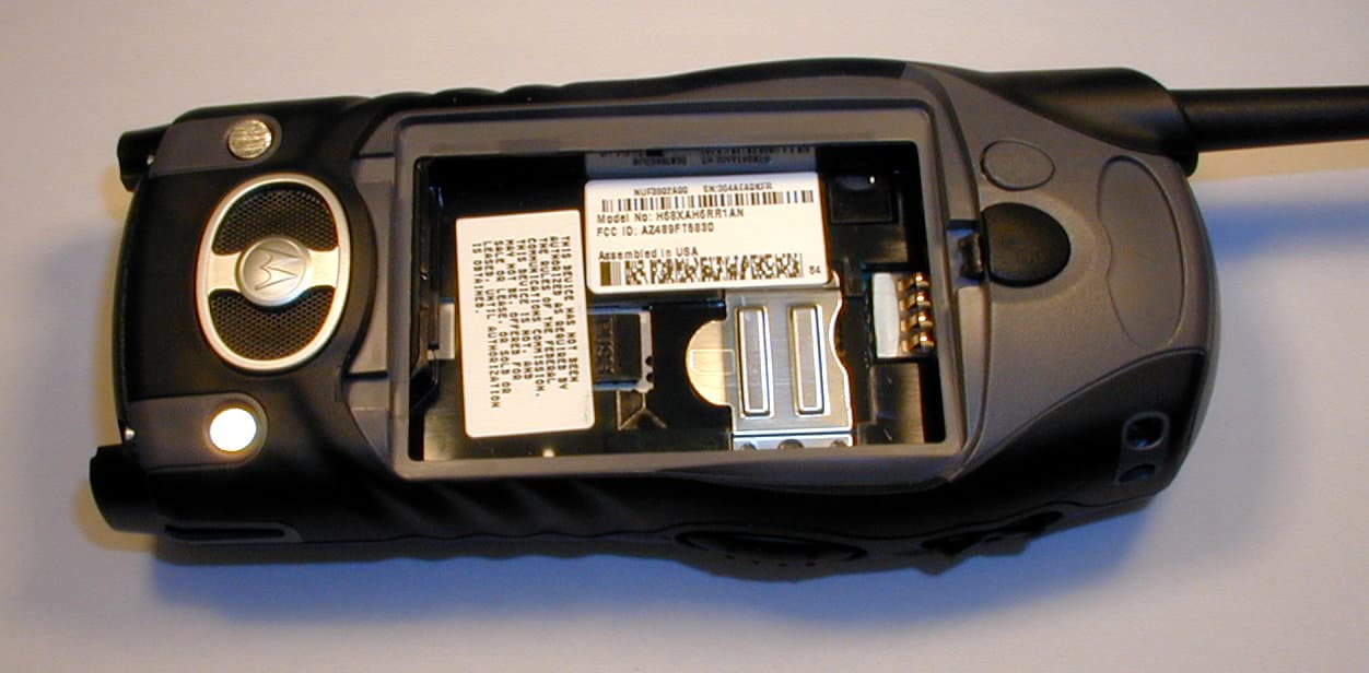
Click to zoom
Application Details
- Equipment Class
- DSS - Part 15 Spread Spectrum Transmitter
- Date of Grant
- Dec 13, 2006
- Application Purpose
- Original Equipment
- Date of Application
- Dec 13, 2006
- Equipment Note
- iDEN i325 WITH MOTOTalk
- Frequency Range
- 902.52500000 - 927.47500000
- Company
- Motorola Solutions, Inc.
- Country
- United States
Documents & Files
Document Text
Text extracted from the exhibit documents filed with the FCC. Open a document above to read the original.
Users Manual
Motorola iDEN Digital Multi-service Data-capable Phone i 325 Phone User’s Guide @NNTN5837A@NNTN5837A IMPORTANT NOTICE: PLEASE READPRIOR TO USING YOUR PHONEThe SIM card provided in this kit is intended for use withthe phone provided in this package.Loss of certain features will result when using a SIMcard from one of the following models: i 30 sx , i 35 s , i 50 sx , i 55 sr , i 58 sr , i 60 c , i 80 s , i 85 s , i 88 s , i 90 c , i 95 cl series, and the i 2000 series. For more information on SIM card compatibility, go towww.motorola.com/iden/support.Defects or damage to your Motorola phone that resultfrom the use of non-Motorola branded or certifiedAccessories, including but not limited to replacementhousings and or other peripheral accessories, areexcluded from warranty coverage. Please refer to thetext of Motorola's Limited One Year warranty located inthis user’s guide for complete details. i ContentsGetting Started........................................... 1 Removing the Battery Door ...............................2Locating Your SIM Card ....................................3Activating Service ..............................................6Antenna .............................................................6Maintaining Durability ........................................6Powering On and Off.........................................6Enabling Over-the-Air Security..........................7Finding Your Phone Number.............................8Phone Basics ....................................................9SIM Card Security ...........................................12Locking the Keypad .........................................15Accessories .....................................................16For More Information .......................................16 Making Calls ............................................. 17 Phone Calls .....................................................17Private Calls ....................................................17Receiving Calls................................................17Call Icons.........................................................18 Ways to Enter Calls.........................................18Using Speakerphone.......................................20Using Mute ......................................................21Making Emergency Phone Calls .....................21 MOTOtalk TM ..............................................22 Channels and Codes.......................................23Private MOTOtalk Calls...................................25Emergency Calls Using MOTOtalk .................26Setup Options .................................................26 Call Alerts..................................................28 Sending Call Alerts..........................................28Receiving Call Alerts .......................................28Using the Call Alert Queue..............................28 Recent Calls ..............................................30 Storing Recent Calls to Contacts ....................30Deleting Recent Calls......................................31 Contacts ....................................................32 Viewing Contacts ............................................33Creating Entries ..............................................34Storing Numbers Faster ..................................36 ii Editing Entries .................................................36Deleting Entries ...............................................36Checking Capacity ..........................................37Creating Pauses and Waits.............................37International Numbers .....................................37Accessing Contacts with GSM Phones ...........38 Call Forwarding........................................ 39 Forwarding All Calls ........................................39Turning Off Call Forwarding ............................40Forwarding Missed Calls .................................40Viewing Call Forwarding Settings....................41 Additional Calling Options...................... 42 Call Waiting .....................................................42Call Hold ..........................................................43Making a 3-Way Call .......................................43Creating Pauses and Waits While Dialing.......44Making International Calls ...............................44Setting One Touch PTT...................................44Group Calls .....................................................45Call Timers ......................................................46Using Your Phone as a Modem ......................47 Making TTY Calls ............................................48 Memo .........................................................50Ring Tones ................................................51 Setting Your Phone to Vibrate.........................51Turning Ring Tones Off ...................................51Ring and Vibrate .............................................52Assigning Ring Tones to Contacts ..................53Viewing Ring Tone Assignments ....................53Downloading More Ring Tones .......................53Managing Memory ..........................................53Deleting Custom Ring Tones ..........................54 Entering Text ............................................55 Using Alpha Mode ...........................................55Using Word Mode ...........................................55Special Function Keys.....................................56Using Numeric Mode.......................................57Using Symbols Mode ......................................57 Messages ..................................................58 Message Notifications .....................................58Message Center ..............................................59 iii Voice Mail Messages ............................... 60 Receiving a Message ......................................60Accessing Voice Mail from the Message Center ...................................60 Send…
Text truncated - open the document above for the full version.
Cover Letter(s)
FCC ID: AZ489FT5855 iDEN, Motorola Inc., 8000 W. Sunrise Blvd., Plantation, FL 33322 www.mot.com/iDEN Page: 13- 1 8 December 2006 Authorization & Evaluation Division Federal Communications Commission Laboratory 7435 Oakland Mills Road Columbia, MD 21046 Subject: Application for Certification of transmitter with FCC ID: AZ489FT5855. Gentlemen; Motorola Inc., 8000 West Sunrise Boulevard, Fort Lauderdale, Florida 33322, herein submits its application for Certification of the transmitter with FCC ID: AZ489FT5855. This variable output power (0.088 to 700 milliwatts) transmitter is part of a handheld transceiver used in an SMR and EA SMR trunking system operating in the United States 806-821/851-866 MHz and 896-901/935-940 MHz frequency band. Operation is also extended for use in a Narrowband PCS system operating in the United States in the spectrum between 901-902/940-941 MHz, on channels which the licensee has aggregated together to form twenty-one 25 kHz operating channels. It also possesses a transmitter that operates in the ISM band (902 – 928 MHz). The two transmitters are configured so that they can only operate exclusive of each other (i.e. only one mode can operate at a time). The operation mode is selected via the user menu. Certification is also sought for this transceiver, and performance data is provided for that purpose. The first transceiver is of the receive-first type described in International Telecommunications Union Recommendation ITU-R M.1221 entitled Technical and Operational Requirements for Cellular Multimode Mobile Radio Stations. It must first find, acquire and lock onto a control channel from a predefined set of control channel frequencies assigned to a companion Authorized base station (e.g. – FCC ID: ABZ89FC5794). Transmission is not possible until lock to a base station control channel has been achieved, then transmission is limited to digitally modulated service request bursts on the reverse control channel. Upon recognition of a proper request, the control channel base station transmitter will then assign the transceiver a traffic channel for transmission of digital voice or circuit-switched data from the set of frequencies for which the trunking system is licensed. Attached Exhibit 12.1 provides additional descriptive details. FCC ID: AZ489FT5855 iDEN, Motorola Inc., 8000 W. Sunrise Blvd., Plantation, FL 33322 www.mot.com/iDEN Page: 13- 2 To facilitate global roaming it is kindly requested that a note be provided in the Grant for Equipment Authorization, which states that this ‘receive first’ type of equipment is compliant for transmitter operation over the broader range 806-825 MHz when used with a compatible Authorized Base Station. This will aid equipment authorization in foreign countries, which accept a United States FCC Grant for Equipment Authorization, yet not jeopardize United States public safety or cellular systems licensed to operate in the 821- 825 MHz frequency band since no compatible base station may be authorized on those frequencies in the United States. It is also expected that this transceiver type will be marketed outside the United States and brought into the United States for itinerant “roaming” operation on compatible 806 - 821 MHz base stations located within the United States. Consequently, upon receipt of Authorization, only those units of this equipment type authorized for marketing in countries outside the United States will also bear a label with the specified FCC identifier. In accordance with 47 CFR 2.1093(c) this transmitter may be used in “covered” SMR and Personal Communications Services so it has been subjected to routine environmental evaluation for RF exposure and found to be compliant with the limits specified in 47 CFR 2.1093(d)(2). The subject transmitter complies with 47 CFR 90.203 of the rules in that the operator cannot directly program transmit frequencies using only the unit's normally accessible external controls. The second transceiver is a frequency hopping spread spectrum type, operating in the unlicensed ISM (902-928 MHz) band. It uses an FSK (Frequency Shift Key) modulation, 50 kHz spacing, up to 1 watt. The protocol is defined to have 10 interleaved hopsets of 50 frequencies each with 500 kHz separation between set members. All 10 hopsets span the entire ISM band. In this transceiver mode, conversations are held only via the speakerphone; the earpiece is disabled. This transceiver can function as a Part 15.3(r) computer peripheral device when functioning as an RF modem when connected to a computer via a data cable (ref: Exhibit 12.4). For this reason a Declaration of Conformity has been prepared and is provided on Page vi (10 th page) of the User Manual in the Exhibit 8. Enclosed is a complete Certification Application comprised of 13 Exhibits. Contact me at (954) 723-5793 if you require any additional information. Sincerely, /s/ Mike Ramnath (signed) Manager, Regulatory Compliance Email: [email protected]
Cover Letter(s)
FCC ID: AZ489FT5855 ______________________________________________________________________________ Motorola Inc, 8000 West Sunrise Boulevard, Fort Lauderdale, Florida 33322. CONFIDENTIALITY REQUESTED 8 December 2006 Authorization & Evaluation Division Federal Communications Commission Laboratory 7435 Oakland Mills Road Columbia, MD 21046 Subject: Confidentiality Request for Transmitter with FCC ID: AZ489FT5855. Dear Sir or Madam: Motorola is requesting that Exhibit 4 (Circuit Descriptions), Exhibit 5 (Schematic Diagrams), Exhibit 10 (Parts List and Tune-Up Procedures), and Exhibit 12 (Transmitter Description) not be made routinely available for public inspection. Motorola considers the information in these exhibits should be classified as trade secrets, pursuant to 47 CFR Section 0.457(d) and Section 552(b)(4) of the Freedom of Information Act. Motorola is also requesting that the FCC mark Exhibit 3 (External Photos) and Exhibit 9, (Internal Photos) as Temporary Confidentiality as outlined in Public Notice DA 04-1705, dated June 15, 2004. This provision will give Motorola temporary confidentiality prior to product launch. Please mark Exhibits 4, 5, 10, and 12 as “Confidential” And Exhibit 3 and 9 as “Temporary Confidential”. Please contact me if you require any additional information. Sincerely, /s/ Mike Ramnath (signed) Manager, Regulatory Compliance Tel: (954) 723-5793 E-mail: [email protected] EXHIBIT 13b
Cover Letter(s)
EXHIBIT 13A SHEET 1 FCC ID: AZ489FT5855 Date: 8 st December 2006 Authorization & Evaluation Division Federal Communications Commission Laboratory 7435 Oakland Mills Road Columbia, MD 21046 Subject: Labelling Proposal for Transmitter with FCC ID: AZ489FT5855. Dear Sir / Madam, Motorola Inc., 8000 West Sunrise Blvd., Fort Lauderdale, FL, herein submits it’s Labelling Proposal for the Transmitter with FCC ID: AZ489FT5855. Motorola complies to FCC Rule Part 2.925 (d) that the label is permanently affixed and is readily visible to the purchaser at the time of purchase”. Further, at the time of purchase, batteries are shipped in another section or compartment of the radio packaging and are not attached to the radio. In some instances they may be shipped in separate boxes. So, the customer needs to physically install the battery by removing the battery cover, if any, or attach the battery before using the radio. Hence, the FCC label would be visible to the user every time he goes through that exercise! Thus meeting the requirement of FCC Rule Part 2.925 (d). Further, the placement of the label in the battery compartment is done because space is limited on the exterior of the device. The battery compartment also helps to protect the label from getting obliterated or made unreadable through regular handling and use. It also helps when to further protect the label when it is being used in hazardous situations by Police, Fire and other EMS Services. Please contact me at 954-723-5793 if you require any additional information. Sincerely, /s/ Mike Ramnath (signed) Mike Ramnath Manager, Regulatory Compliance Email: [email protected]
Cover Letter(s)
KDB Inquiry Tracking Number - 506627
External Photos
FCC Filing Package for Motorola i325 Transceiver FCC ID: AZ489FT5855 iDEN, Motorola Inc., 8000 W. Sunrise Blvd., Plantation, FL 33322, USA WWW.MOT.COM/iDEN Page: 3 - 1 Exhibit 3: External Photographs -- Pursuant to 47 CFR 2.1033(c) 12 Temporary Confidentiality Requested The radio product shapes, colors and housing/bezel may vary. Stylistic changes to the appearance of the antenna do not affect antenna performance. Figure 3-1. Photograph of Front. Figure 3-2. Photograph of back. FCC Filing Package for Motorola i325 Transceiver FCC ID: AZ489FT5855 iDEN, Motorola Inc., 8000 W. Sunrise Blvd., Plantation, FL 33322, USA WWW.MOT.COM/iDEN Page: 3 - 2 Figure 3-3 Connector Cover Closed. Figure 3-4 Connector Cover Open. Figure 3-5. Location of the FCC label in the phone. Figure 3-6. FCC / Industry Canada Label Model No: H68XAH6RR1BN FCC ID: AZ489FT5855 IC: 109U-89FT5855
ID Label/Location Info
FCC Filing Package for Motorola i325 Transceiver FCC ID: AZ489FT5855 iDEN, Motorola Inc., 8000 W. Sunrise Blvd., Plantation, FL 33322, USA WWW.MOT.COM/iDEN Pag e 1 - 1 Exhibit 1: Identification Label -- Pursuant to 47 CFR 2.925, 2.1065 and 2.1033(c) 11 1.1 Location Back side of the radio product unit’s chassis (Photograph 1.1). Please note that Motorola complies with FCC Rule Part 2.925 (d) that the label is permanently affixed and is readily visible to the purchaser at the time of purchase. 1.2 Type The label is of a white polyester film laminate with a pressure sensitive adhesive backing. The adhesive is a permanent type acrylic with minimum peel strength of 5 lbs/in. 1.3 Markings (Text) Enlarged view of label showing FCC ID and manufacturer type number: Photograph 1.1: Back of radio battery compartment, showing label locations. Photograph 1.2: Detail view of FCC / Industry Canada Label. Model No: H68XAH6RR1BN FCC ID: AZ489FT5855 IC: 109U-89FT5855 FCC Filing Package for Motorola i325 Transceiver FCC ID: AZ489FT5855 iDEN, Motorola Inc., 8000 W. Sunrise Blvd., Plantation, FL 33322, USA WWW.MOT.COM/iDEN Pag e 1 - 2 Exhibit 1A: General Information 1A.1 Production Plans Quantity production is planned. 1A.2 Application References -- Pursuant to 47 CFR 2.948 and 2.1061 Reference is made to the following Motorola "Application References" 1. Open Area Test Site “OATS” (FCC Registration: 95517 and 98377 / Industry of Canada: 2056-A) 2. TIMCO Engineering Lab, 849 NW State Road. 45Newberry, Florida 32669 3. FAU EMI Lab, Florida Atlantic University, 3998 N.W. 8th Street (FAU Blvd) Suite #310, Boca Raton, FL 33431. 1A.3 Data Submittal Procedure Data located in Exhibit 6 is supplied in accordance with 47CFR2, Subpart J, Part 15 Subparts A, B, and C; Part 90, Subparts I and S; and Part 24, Subparts A, B, C, and D of the Commission’s rules. 1A.4 Similar, currently Certified Transceiver FCC ID: AZ489FT5830 1A.5 Additional Considerations This transceiver possesses two distinct modes of operation (iDEN in the Part 90 800/900 MHz SMR spectrum, and in the Narrowband PCS spectrum between 901-902 MHz) and MOTOtalk (FHSS in the 900 MHz ISM band). The operation mode is selected via the user menu. The two transceivers can only operate independent of each other and only one mode can operate at a time. The first transceiver is of the receive-first type described in International Telecommunications Union Recommendation ITU-R M.1221 entitled Technical and Operational Requirements for Cellular Multimode Mobile Radio Stations. It must first find, acquire and lock onto a control channel from a predefined set of control channel frequencies assigned to a companion Authorized base station (e.g. – FCC ID: ABZ89FC5794). Transmission is not possible until lock to a base station control channel has been achieved, then transmission is limited to digitally modulated service request bursts on the reverse control channel. Upon recognition of a proper request, the control channel base station transmitter will then assign the transceiver a traffic channel for transmission of digital voice or circuit-switched data from the set of frequencies for which the trunking system is licensed. Attached Exhibit 12.1 provides additional descriptive details. The second transceiver is a frequency hopping spread spectrum type, operating in the unlicensed ISM (902-928 MHz) band. It uses an 8FSK (Frequency Shift Key) modulation, 50 kHz spacing up to 1 watt. The protocol is defined to have 10 interleaved hop sets of 50 frequencies each with 500 kHz separation between set members. All 10 hop sets span the entire ISM band. In the ISM transceiver mode, conversations are held only via the speakerphone; the earpiece is disabled. FCC Filing Package for Motorola i325 Transceiver FCC ID: AZ489FT5855 iDEN, Motorola Inc., 8000 W. Sunrise Blvd., Plantation, FL 33322, USA WWW.MOT.COM/iDEN Pag e 1 - 3 This radio product also integrates a receiver that will receive and process signals from Global Positioning System satellites. The radio product can also function as a Part 15.3(r) computer peripheral device when functioning as an RF modem when connected to a computer via a data cable accessory (Exhibit 12). A Declaration of Conformity in accordance with 47CFR 2.1077(a) is provided in Exhibit 8 as evidence of compliance with Part 15 requirements for these additional Class B digital device functionalities per 47CFR15.101(a). Compliance with Part 15 requirements for the Direct-Conversion (zero IF superheterodyne) receiver has been determined by verification in accordance with 47CFR15.1.
Internal Photos
FCC Filing Package for Motorola i325 Transceiver FCC ID: AZ489FT5855 iDEN, Motorola Inc., 8000 W. Sunrise Blvd., Plantation, FL 33322, USA WWW.MOT.COM/iDEN Page: 9- 1 Exhibit 9: Internal Photographs -- Pursuant to 47 CFR 2.1033(c) 12 Temporary Confidentiality Requested Photograph 9-1: Internal photo with shields intact Photograph 9-2: Internal photo with shields intact. FCC Filing Package for Motorola i325 Transceiver FCC ID: AZ489FT5855 iDEN, Motorola Inc., 8000 W. Sunrise Blvd., Plantation, FL 33322, USA WWW.MOT.COM/iDEN Page: 9- 2 Photograph 9-3: Internal photo showing the keypad and display. Photograph 9-4: Internal photo of electronic assembly with shields removed. Photograph 9-5: Internal photo of electronic assembly with shields removed.
RF Exposure Info
CGISS EME Form-SAR-Rpt-Rev. 2.00 Page 1 of 24 N&E EME Test Laboratory 8000 West Sunrise Blvd Fort Lauderdale, FL. 33322 S.A.R. EME Compliance Test Report Part 1 of 2 Note: Based on the information and the testing results provided herein, the undersigned certifies that when used as stated in the operating instructions supplied, said product complies with the national and international reference standards and guidelines listed in section 2.0 of this report. ______________________Signature on file______________________________________ ________12/07/06_________________ Deanna Zakharia Date Approved Senior Resource Manager, Laboratory Director, N&E EME Lab Note: This report shall not be reproduced without written approval from an officially designated representative of the Motorola EME Laboratory. Date of Report: December 07, 2006 Report Revision: Rev. A Manufacturer: Motorola Product Description: i325; Dual mode iDEN: 1:6, 1:3, 81:120, 1:12 TDMA; 64 QAM, 16 QAM & QPSK Modulation; 0.6 W Pulse average nominal; MOTOtalk: 114:120 8FSK, 0.85W nominal GPS capable FCC ID: AZ489FT5855 Device Model: H68XAH6RR1AN Certificate Number: 2518.01 Test Period: 2/8/04-2/13/04 EME Tech: Ed Church EME Eng.: Stephen Whalen (Sr. EME Eng.), Deanna Zakharia (Elect. Principle Staff Eng.) Author: Michael Sailsman Global EME Regulatory Affairs Liaison CGISS EME Form-SAR-Rpt-Rev. 2.00 Page 2 of 24 TABLE OF CONTENTS Part 1 of 2 1.0 Introduction 2.0 Reference Standards and Guidelines 3.0 Description of Test Sample 3.1 Test Signal 3.2 Test Output Power 4.0 Description of Test Equipment 4.1 Description of S.A.R Measurement System 4.2 Description of Phantom 4.2.1 Flat Phantom 4.2.2 SAM phantom 4.3 Simulated Tissue Properties 4.3.1 Type of Simulated Tissue 4.3.2 Simulated Tissue Composition (System Performance) 4.4 Test conditions 5.0 Description of Test Procedure 5.1 Device Test Positions 5.1.1 Body 5.1.2 Head 5.1.3 Face 5.2 Test Position Photographs 5.3 Probe Scan Procedures 6.0 Measurement Uncertainty 7.0 S.A.R. Test Results 7.1 S.A.R. results 7.2 Peak S.A.R. location 7.3 Highest S.A.R. results calculation methodology 8.0 Conclusion Part 2 of 2 Appendix A: Power Slump Data/Shortened scan Appendix B: Data Results Appendix C: Dipole System Performance Check Results Appendix D: Calibration Certificates Appendix E: Illustration of Body-worn Accessories Appendix F: Accessories and options test status and separation distances CGISS EME Form-SAR-Rpt-Rev. 2.00 Page 3 of 24 REVISION HISTORY Date Revision Comments 2/19/04 O Release of Prototype results 12/07/06 A Revised report includes the following changes; FCC ID from AZ489FT5830 (grant date 04/28/2004 for Parts 15 and 90) to AZ489FT5855 (Parts 15, 90 and 24), Lab Manager, A2LA Certificate number. Updated Laboratory name CGISS EME to N&E EME on front cover pages Part 1 & 2. CGISS vs. N&E are name changes only, the Laboratories are one of the same and therefore CGISS remains within the report context. CGISS EME Form-SAR-Rpt-Rev. 2.00 Page 4 of 24 1.0 Introduction This report details the utilization, test setup, test equipment, and test results of the Specific Absorption Rate (S.A.R.) measurements performed at the CGISS EME Test Lab for model number H68XAH6RR1AN, FCC ID: AZ489FT5855. The applicable exposure environment is General Population/Uncontrolled. 2.0 Reference Standards and Guidelines This product is designed to comply with the following national and international standards and guidelines. • United States Federal Communications Commission, Code of Federal Regulations; 47CFR part 2 sub-part J • IEEE 1528, 2003 "Recommended Practice for Determining the Peak Spatial-Average Specific Absorption Rate (SAR) in the Human Head from Wireless Communications Devices: Measurement Techniques" • American National Standards Institute (ANSI) / Institute of Electrical and Electronic Engineers (IEEE) C95. 1-1992 • Institute of Electrical and Electronic Engineers (IEEE) C95.1-1999 Edition • International Commission on Non-Ionizing Radiation Protection (ICNIRP) 1998 • Ministry of Health (Canada) Safety Code 6. Limits of Human Exposure to Terminal frequency Electromagnetic Fields in the Frequency Range from 3 kHz to 300 GHz, 1999 • Australian Communications Authority Radiocommunications (Electromagnetic Radiation - Human Exposure) Standard 2003 • ANATEL, Brazil Regulatory Authority, Resolution 256 (April 11, 2001) "additional requirements for SMR, cellular and PCS product certification." CGISS EME Form-SAR-Rpt-Rev. 2.00 Page 5 of 24 3.0 Description of Test Sample FCC ID: AZ489FT5855 is a dual mode digital multi-service device with data capability that employs time division multiplexing transmission technology having a duty cycle ranging from 16.67% to 33.33% and using 16-QAM modulation for voice or circuit data transmission. There is a Split 1:3 mode that operates using a 16.67% transmission duty cycle. In this mode two 7.5ms pulses occur during the six time slots within the 90-msec frame format. The Split 1:3 mode is available in both the 806-825MHz and 896- 902MHz bands but only when in the telephone interconnect mode. Packet data transmission is also supported up to a maximum duty cycle of 67.5% using quad QPSK modulation. MOTOtalk is a knifeswitch transmitting mode that employs Frequency Hopping Digital Spread Spectrum within the 900MHz ISM band, having a duty cycle of 114:120, and using 8FSK modulation. MOTOtalk also incorporates a high audio output feature. This device will be marketed to and used by the general population. This device may be used while held against the head in voice mode, in front of the face in PTT mode, and against the body in voice, PTT and data modes. In the MOTOtalk mode the device can only be used for dispatch (i.e. PTT) operations. In MOTOtalk mode the device may be positioned in front of the face or against the body (in high audio mode). FCC ID: AZ489FT5855 is capable of operating in the 806-825 MHz and 896-902MHz bands. Packet data transmission is not available…
Text truncated - open the document above for the full version.
RF Exposure Info
CGISS EME Form-SAR-Rpt-Rev. 2.00 Page 1 of 48 N&E EME Test Laboratory 8000 West Sunrise Blvd Fort Lauderdale, FL. 33322 S.A.R. EME Compliance Test Report Part 2 of 2 Note: Based on the information and the testing results provided herein, the undersigned certifies that when used as stated in the operating instructions supplied, said product complies with the national and international reference standards and guidelines listed in section 2.0 of this report. _______________signature on file_____________________________________________ ____12/07/06_____________________ Deanna Zakharia Date Approved Senior Resource Manager, Laboratory Director, N&E EME Lab Note: This report shall not be reproduced without written approval from an officially designated representative of the Motorola EME Laboratory. Certificate Number: 2518.01 Date of Report: December 07, 2006 Report Revision: Rev. A Manufacturer: Motorola Product Description: i325; Dual mode iDEN: 1:6, 1:3, 81:120, 1:12 TDMA; 64 QAM, 16 QAM & QPSK Modulation; 0.6 W Pulse average nominal; MOTOtalk: 114:120 8FSK, 0.85W nominal GPS capable FCC ID: AZ489FT5855 Device Model: H68XAH6RR1AN Test Period: 2/8/04-2/13/04 EME Tech: Ed Church EME Eng.: Stephen Whalen (Sr. EME Eng.), Deanna Zakharia (Elect. Principle Staff Eng.) Author: Michael Sailsman Global EME Regulatory Affairs Liaison CGISS EME Form-SAR-Rpt-Rev. 2.00 Page 2 of 48 APPENDIX A Power Slump Data/Shortened Scan CGISS EME Form-SAR-Rpt-Rev. 2.00 Page 3 of 48 DUT Power versus time data CGISS EME Form-SAR-Rpt-Rev. 2.00 Page 4 of 48 Shortened Scan Results FCC ID: AZ489FT5855; Test Date: 2/11/04 Motorola CGISS EME Laboratory Run #: Ab-R1-040211-05 Model #: H68XAH6RR1AN SN: 364ADY005C TX Freq: 813.5125 MHZ Tissue Temp: 20.5 (Celsius) Start Power: .725 W Antenna: Fixed Battery Kit: SNN5706A Carry case: None Audio/Data Acc.: None Shortened scan reflect highest S.A.R. producing configuration; Run time 7 minutes. Representative “normal” scan run time was 27 minutes “Shortened” scan max calculated S.A.R. using S.A.R. drift: 1-g Avg. = 0.927 mW/g; 10-g Avg. = 0.663mW/g “Normal” scan max calculated S.A.R. using S.A.R. drift: 1-g Avg. = 1.092 mW/g; 10-g Avg. = 0.772mW/g (see section 7.1 run # EC-Ab-R1-040213-04) DUT back towards the phantom with antenna separated 2.5cm Flat Phantom Phantom; Device Section; Position: (90°,90°); Probe: ET3DV6 - SN1384(Cal Date 05-15-2003); ConvF(6.50,6.50,6.50); Probe cal date: 15/05/03; Crest factor: 1.5; FCC Body 813 MHz: σ = 0.94 mho/m ε = 53.6 ρ = 1.00 g/cm3; DAE3: 363V1 DAE Cal Date: 05/13/2003 Cube 5x5x7: SAR (1g): 0.927 mW/g, SAR (10g): 0.663 mW/g, (Worst-case extrapolation) Cube 5x5x7: Dx = 8.0, Dy = 8.0, Dz = 5.0; SAR (1g): 0.927 mW/g, SAR (10g): 0.663 mW/g Power Drift: -0.11 dB CGISS EME Form-SAR-Rpt-Rev. 2.00 Page 5 of 48 FCC ID: AZ489FT5855; Test Date: 2/13/04 Motorola CGISS EME Laboratory Run #: EC-Lear-R1-040213-02 Model #: H68XAH6RR1AN SN: 364ADY005C TX Freq: 898.49375 MHz Sim Tissue Temp: 21.0 (Celsius) Start Power: 0.669 W Antenna: Fixed Battery Kit: SNN5705B Carry Case: NONE Audio/Data Acc.: NONE Shortened scan reflect highest S.A.R. producing configuration; Run time 7 minutes. Representative “normal” scan run time was 27 minutes “Shortened” scan max calculated S.A.R. using S.A.R. drift: 1-g Avg. = 0.978 mW/g; 10-g Avg. = 0.643 mW/g “Normal” scan max calculated S.A.R. using S.A.R. drift: 1-g Avg. = 1.055 mW/g; 10-g Avg. = 0.686 mW/g (see section 7.1 run # EC-Lear-R1-040208-14) DUT at the Left ear in 15 º tilt position SAM; Position: (90°,59°); Probe: ET3DV6 - SN1384(Cal Date 05-15-2003); ConvF(6.60,6.60,6.60); Probe cal date: 15/05/03; Crest factor: 3.0; IEEE Head 899 MHz:…
Text truncated - open the document above for the full version.
Contact Information
Applicant
Arine Lee(Certification Manager)
Test Firm
MotorolaWilliam Elliott
Technical Specifications
| # | Rule Parts | Frequency Range | Power Output |
|---|---|---|---|
| 1 | 15C | 902.525 MHz - 927.475 MHz | 891.00 mW |
Other Applications from Motorola Solutions, Inc.

AZ489FT4980
Sep 08, 2026Portable two way radio
Equipment Class
TNF - Licensed Non-Broadcast Transmitter Held to FaceAZ489FT4981
Aug 14, 2026Handheld Portable - TANAPA BPR 45 400-470 MHZ 4W NKP
Equipment Class
TNF - Licensed Non-Broadcast Transmitter Held to Face
AZ489FT7187
Jul 13, 2026Portable 2-Way Radio with Bluetooth, Bluetooth LE, WIFI 2.4GHz, WIFI 5GHz, LTE
Equipment Class
DSS - Part 15 Spread Spectrum TransmitterAZ499FT6031
May 11, 2026Operation Critical Wireless Earpiece PTT
Equipment Class
DSS - Part 15 Spread Spectrum Transmitter
AZ499FT5879
Dec 19, 20252-way Portable Radio with BT, BTLE, WIFI, NFC and LTE
Equipment Class
DSS - Part 15 Spread Spectrum Transmitter