AZ489FT6000Bluetooth Option Board Module
Motorola Solutions, Inc.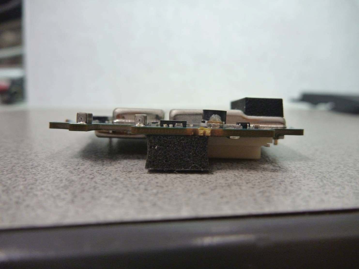
Click to zoom
Application Details
- Equipment Class
- DSS - Part 15 Spread Spectrum Transmitter
- Date of Grant
- Dec 07, 2010
- Application Purpose
- Original Equipment
- Date of Application
- Dec 07, 2010
- Equipment Note
- Bluetooth Option Board Module
- Frequency Range
- 2402.00000000 - 2480.00000000
- Company
- Motorola Solutions, Inc.
- Country
- United States
Documents & Files
Document Text
Text extracted from the exhibit documents filed with the FCC. Open a document above to read the original.
Users Manual
Information to the User The APX Option Board Bluetooth Module (MNUK6000) is intended for integration into Motorola products nly. Therefore it has no stand‐alone User Manual. The following information will be included in the end roduct User Guide: o p FCC/Industry Canada notice ry Canad a Rules. Operation is subject to the following This device complies with Part 15 of the FCC and Indust two conditions: 1. This device may not cause harmful interference; and . This device must accept any interference received, including interference that may cause undesired peration. 2 o FCC RF Exposure Statement his equipment complies with FCC and Industry Canada RF exposure limits set forth for a controlled ce. T environment. End users must follow the specific operating instructions for satisfying exposure complian OTE: Changes or modifications not expressly approved by Motorola could void the user’s authority to perate the equipment. N o Label Information FCC/Industry Canada: If the module is installed inside host devices, then the outside of the device into which the module is installed ust display a label referring to the enclosed module. This exterior label shall use wording such as the ollowing: m f Contains FCC ID: AZ489FT6000 Contains IC: 109U89FT6000
Users Manual
Note: This equipment has been tested and found to comply with the limits for a Class B digital device, pursuant to part 15 of the FCC Rules. These limits are designed to provide reasonable protection against harmful interference in a residential installation. This equipment generates, uses and can radiate radio frequency energy and, if not installed and used in accordance with the instructions, may cause harmful interference to radio communications. However, there is no guarantee that interference will not occur in a particular installation. If this equipment does cause harmful interference to radio or television reception, which can be determined by turning the equipment off and on, the user is encouraged to try to correct the interference by one or more of the following measures: • Reorient or relocate the receiving antenna. • Increase the separation between the equipment and receiver. • Connect the equipment into an outlet on a circuit different from that to which the receiver is connected. • Consult the dealer or an experienced radio/TV technician for help. Page ii ------------------------------------------------------------------------------------------------------------------------------------------------------------------ Additional FCC Note to Users The following FCC information applies to Bluetooth radio options Model Name: MNUK6000 Description: APX7000 Bluetooth Option Board FCC ID: AZ489FT6000 IC ID: 109U-89FT6000 Conforms to the following regulations: FCC Part 15, Section 15.19, 15.21, and 15.105 NOTE: Changes or modifications not expressly approved by Motorola may void the users authority, as authorized by the FCC, to operate this device and should not be made. See 47 CFR Part 15.21. Information to user. The users manual or instruction manual for an intentional or unintentional radiator shall caution the user that changes or modifications not expressly approved by the party responsible for compliance could void the user’s authority to operate the equipment. This device complies with Part 15 of the FCC Rules. Operation is subject to the following two conditions: (1) This device may not cause harmful interference, and (2) this device must accept any interference received, including interference that may cause undesired operation. See 47 CFR Part. 15.19(3). This device has been tested and found to comply with the limits of Part 15.15 of the FCC rules. Parties responsible for equipment compliance should note that the limits specified in this part will not prevent harmful interference under all circumstances. This equipment has been tested and found to comply with the limits for a Class B digital device, pursuant to part 15 of the FCC Rules. See Part 15.105b These limits are designed to provide reasonable protection against harmful interference in a residential installation. This equipment generates, uses and can radiate radio frequency energy and, if not installed and used in accordance with the instructions, may cause harmful interference to radio communications. However, there is no guarantee that interference will not occur in a particular installation. If this equipment does cause harmful interference to radio or television reception, which can be determined by turning the equipment off and on, the user is encouraged to try to correct the interference by one or more of the following measures: • Reorient or relocate the receiving antenna. • Increase the separation between the equipment and receiver. • Connect the equipment into an outlet on a circuit different from that to which the receiver is connected. • Consult the dealer or an experienced radio/TV technician for help. Industry Canada (IC) Statements: This Class B digital apparatus complies with ICES-003 and Radio Standards Specification (RSS) 210. Page iii
Cover Letter(s)
Registergerichth registered in:Vorstandh Board of Directors:7 layers AG, Borsigstrasse 11 Ratingen HRB 3264Dr. Wolfgang Dahm40880 Ratingen, Germany AufsichtsratsvorsitzendehDr. Hans-Jürgen MeckelburgPhone: +49 (0) 2102 749 0 Chairman of the Supervisory Board:Fax: +49 (0) 2102 749 350 Dr. Sabine Grobeckerwww.7layers.com Annex Additional declaration part according FCC 15.247 for Bluetooth TM Devices Version: 2002-06-01 Annex - Additional declaration part according FCC 15.247 for Bluetooth devices Page 2 of 5 pages 1 Output power and channel separation of a Bluetooth device in the different operating modes: The different operating modes (data-mode, acquisition-mode) of a Bluetooth device don’t influence the output power and the channel spacing. There is only one transmitter which is driven by identical input parameters concerning these two parameters. Only a different hopping sequence will be used. For this reason the check of these RF parameters in one op-mode is sufficient. 2 Frequency range of a Bluetooth device: Hereby we declare that the maximum frequency of this device is: 2402 – 2480 MHz. This is according the Bluetooth Core Specification (+ critical errata) for devices which will be operated in the USA. This was checked during the Bluetooth Qualification tests (Test Case: TRM/CA/04-E). Other frequency ranges ( e.g. for Spain, France, Japan) which are allowed according the Core Specification are not supported by this device. 3 Co-ordination of the hopping sequence in data mode to avoid simultaneous occupancy by multiple transmitters: Bluetooth units which want to communicate with other units must be organised in a structure called piconet. This piconet consist of max. 8 Bluetooth units. One unit is the master the other seven are the slaves. The master co-ordinates frequency occupation in this piconet for all units. As the master hop sequence is derived from its BD address which is unique for each Bluetooth device, additional masters intending to establish new piconets will always use different hop sequences. 4 Example of a hopping sequence in data mode: Example of a 79 hopping sequence in data mode: 40, 21, 44, 23, 42, 53, 46, 55, 48, 33, 52, 35, 50, 65, 54, 67, 56, 37, 60, 39, 58, 69, 62, 71, 64, 25, 68, 27, 66, 57, 70, 59, 72, 29, 76, 31, 74, 61, 78, 63, 01, 41, 05, 43, 03, 73, 07, 75, 09, 45, 13, 47, 11, 77, 15, 00, 64, 49, 66, 53, 68, 02, 70, 06, 01, 51, 03, 55, 05, 04 Annex - Additional declaration part according FCC 15.247 for Bluetooth devices Page 3 of 5 pages 5 Equally average use of frequencies in data mode and behaviour for short transmissions: The generation of the hopping sequence in connection mode depends essentially on two input values: 1. LAP/UAP of the master of the connection 2. Internal master clock The LAP (lower address part) are the 24 LSB’s of the 48 BD_ADDRESS. The BD_ADDRESS is an unambiguous number of every Bluetooth unit. The UAP (upper address part) are the 24 MSB’s of the 48 BD_ADDRESS. The internal clock of a Bluetooth unit is derived from a free running clock which is never adjusted and is never turned off. For synchronisation with other units only offset are used. It has no relation to the time of the day. Its resolution is at least half the RX/TX slot length of 312.5 μs. The clock has a cycle of about one day (23h30). In most case it is implemented as 28 bit counter. For the deriving of the hopping sequence the entire LAP (24 bits), 4 LSB’s (4 bits) (Input 1) and the 27 MSB’s of the clock (Input 2) are used. With this input values different mathematical procedures (permutations, additions, XOR- operations) are performed to generate the sequence. This will be done at the beginning of every new transmission. Regarding short transmissions the Bluetooth system has the following behaviour: The first connection between the two devices is established, a hopping sequence was generated. For transmitting the wanted data the complete hopping sequence was not used. The connection ended. The second connection will be established. A new hopping sequence is generated. Due to the fact that the Bluetooth clock has a different value, because the period between the two transmission is longer (and it cannot be shorter) than the minimum resolution of the clock (312.5 μs). The hopping sequence will always differ from the first one. 6 Receiver input bandwidth and behaviour for repeated single or multiple packets: The input bandwidth of the receiver is 1 MHz. In every connection one Bluetooth device is the master and the other one is the slave. The master determines the hopping sequence (see chapter 5). The slave follows this sequence. Both devices shift between RX and TX time slot according to the clock of the master. Additionally the type of connection (e.g. single or multislot packet) is set up at the beginning of the connection. The master adapts its hopping frequency and its TX/RX timing according to the packet type of the connection. Also the slave of the connection will use these settings. Repeating of a packet has no influence on the hopping sequence. The hopping sequence generated by the master of the connection will be followed in any case. That means, a repeated packet will not be send on the same frequency, it is send on the next frequency of the hopping sequence. Annex - Additional declaration part according FCC 15.247 for Bluetooth devices Page 4 of 5 pages 7 Dwell time in data mode The dwell time of 0.3797s within a 30 second period in data mode is independent from the packet type (packet length). The calculation for a 30 second period is a follows: Dwell time = time slot length * hop rate / number of hopping channels *30s Example for a DH1 packet (with a maximum length of one time slot) Dwell time = 625 μs * 1600 1/s / 79 * 30s = 0.3797s (in a 30s period) For multislot packet the hopping is reduced according to the length of the packet. Example for a DH5 packet (with a maximum length of five time slots) Dwell time = 5 * 625 μs * 1600 * 1/5 *1/s / 79 * 30s = …
Text truncated - open the document above for the full version.
Cover Letter(s)
7 layers AG Borsigstr.11 40880 Ratingen Germany Attn: Reviewing Engineer Federal Communications Commission 7435 Oakland Mills Road Columbia, MD 21046 CONFIDENTIALITY REQUEST FOR FCC-ID: AZ489FT6000 Sirs, In accordance with FCC Rule Section 0.457 and 0.459 of CFR 47, 7 layers AG (authorized by Motorola) hereby requests schematic diagrams, parts list, operational description and Block diagrams submitted with this application to be withheld from public review. These documents contain detailed system and equipment description and related information about the product, which Motorola considers to be proprietary. This information should never get into the possession of competitors, which would be harmful for our business. Do not hesitate to contact me if you have any additional questions. Patrick Lomax Ratingen, 2010-11-09
Cover Letter(s)
Registergericht registered in:Vorstand Board of Directors:7 layers AG, Borsigstrasse 11 Ratingen, HRB 3264Dr. Wolfgang Dahm40880 Ratingen, Germany Aufsichtsratsvorsitzende Dr. Hans-Jürgen MeckelburgPhone: +49 (0) 2102 749 0 Chairman of the Supervisory Board:Fax: +49 (0) 2102 749 350 Dr. Sabine Grobeckerwww.7Layers.com Patrick Lomax 8/23/2010 Phone +49 (0) 2102 749 380 Fax +49 (0) 2102 749 350 Email: [email protected] Request for a modular approval - FCC ID AZ489FT6000 Dear Application Examiner, the _Motorola__ module MNUK6000 is seeking FCC authorization as a modular transmitter. The requirement of the FCC part 15.212 are met. The following requirements are fulfilled: 1. The radio portion of the module is contained in its own RF shielding. The radio portion of the module has its own shielding. 2. The modular transmitter must have buffered modulation/data inputs The module has a memory management unit inside of the IC that buffers the data inputs. 3. The modular transmitter must have its own power supply regulation The IC contains its own voltage regulator. In case of changes in supply voltage VCC (by temperature change or other), the internal voltage will be stabilized. 4. The modular transmitter must comply with the antenna requirements of Section 15.203 and 15.204c The transmitter has been tested with dedicated antenna. Attn: Application Examiner Federal Communications Commission 7435 Oakland Mills Road Columbia, MD 21046 - 2 - 5. The modular transmitter must be tested in a stand-alone configuration The EUT was tested in a stand alone configuration with dedicated antenna. 6. The modular transmitter must be labelled with its own FCC ID number The module is labelled with its own FCC ID. 7. The modular transmitter must comply with any specific rule or operating requirements applicable to the transmitter and the manufacturer must provide adequate instructions along with the module to explain any such requirements. The EUT is compliant with all applicable FCC rules. 8. The modular transmitter must comply with any applicable RF exposure requirements. The device and its antenna must not be co-located or operating in conjunction with any other antenna or transmitter. Please contact us if you have any additional questions. Best Regards 7layers AG
External Photos
FCC Regulatory Filings- Bluetooth Option Board Module August 18, 2010 Motorola Confidential Restricted , FCC_Filing_revA.ppt, Rev. A Add additional legal text here if required by your local Legal Counsel. MOTOROLA and the Stylized M Logo are registered in the US Patent & Trademark Office. All other product or service names are the property of their respective owners. © 2010 Motorola . All rights reserved. External PhotosE xternal Photos FCC Regulatory Filings- Bluetooth Option Board Module August 18, 2010 Motorola Confidential Restricted , FCC_Filing_revA.ppt, Rev. A Add additional legal text here if required by your local Legal Counsel. MOTOROLA and the Stylized M Logo are registered in the US Patent & Trademark Office. All other product or service names are the property of their respective owners. © 2010 Motorola . All rights reserved. 2. External Photos- Side 1 FCC Regulatory Filings- Bluetooth Option Board Module August 18, 2010 Motorola Confidential Restricted , FCC_Filing_revA.ppt, Rev. A Add additional legal text here if required by your local Legal Counsel. MOTOROLA and the Stylized M Logo are registered in the US Patent & Trademark Office. All other product or service names are the property of their respective owners. © 2010 Motorola . All rights reserved. 2. External Photos- Side 2 FCC Regulatory Filings- Bluetooth Option Board Module August 18, 2010 Motorola Confidential Restricted , FCC_Filing_revA.ppt, Rev. A Add additional legal text here if required by your local Legal Counsel. MOTOROLA and the Stylized M Logo are registered in the US Patent & Trademark Office. All other product or service names are the property of their respective owners. © 2010 Motorola . All rights reserved. 2. External Photos- Side 3 FCC Regulatory Filings- Bluetooth Option Board Module August 18, 2010 Motorola Confidential Restricted , FCC_Filing_revA.ppt, Rev. A Add additional legal text here if required by your local Legal Counsel. MOTOROLA and the Stylized M Logo are registered in the US Patent & Trademark Office. All other product or service names are the property of their respective owners. © 2010 Motorola . All rights reserved. 2. External Photos- Side 4 FCC Regulatory Filings- Bluetooth Option Board Module August 18, 2010 Motorola Confidential Restricted , FCC_Filing_revA.ppt, Rev. A Add additional legal text here if required by your local Legal Counsel. MOTOROLA and the Stylized M Logo are registered in the US Patent & Trademark Office. All other product or service names are the property of their respective owners. © 2010 Motorola . All rights reserved. 2. External Photos- Side 5 FCC Regulatory Filings- Bluetooth Option Board Module August 18, 2010 Motorola Confidential Restricted , FCC_Filing_revA.ppt, Rev. A Add additional legal text here if required by your local Legal Counsel. MOTOROLA and the Stylized M Logo are registered in the US Patent & Trademark Office. All other product or service names are the property of their respective owners. © 2010 Motorola . All rights reserved. 2. External Photos- Side 6
ID Label/Location Info
MNUK6000 FCC & IC Label Motorola Confidential Restricted
Internal Photos
FCC Regulatory Filings- Bluetooth Option Board Module August 18, 2010 Motorola Confidential Restricted , FCC_Filing_revA.ppt, Rev. A Add additional legal text here if required by your local Legal Counsel. MOTOROLA and the Stylized M Logo are registered in the US Patent & Trademark Office. All other product or service names are the property of their respective owners. © 2010 Motorola . All rights reserved. 1. Internal Photos- Top Side (NS) FCC Regulatory Filings- Bluetooth Option Board Module August 18, 2010 Motorola Confidential Restricted , FCC_Filing_revA.ppt, Rev. A Add additional legal text here if required by your local Legal Counsel. MOTOROLA and the Stylized M Logo are registered in the US Patent & Trademark Office. All other product or service names are the property of their respective owners. © 2010 Motorola . All rights reserved. 1. Internal Photos- Bottom Side (NS) FCC Regulatory Filings- Bluetooth Option Board Module August 18, 2010 Motorola Confidential Restricted , FCC_Filing_revA.ppt, Rev. A Add additional legal text here if required by your local Legal Counsel. MOTOROLA and the Stylized M Logo are registered in the US Patent & Trademark Office. All other product or service names are the property of their respective owners. © 2010 Motorola . All rights reserved. 1. Internal Photos- Top Side (S) FCC Regulatory Filings- Bluetooth Option Board Module August 18, 2010 Motorola Confidential Restricted , FCC_Filing_revA.ppt, Rev. A Add additional legal text here if required by your local Legal Counsel. MOTOROLA and the Stylized M Logo are registered in the US Patent & Trademark Office. All other product or service names are the property of their respective owners. © 2010 Motorola . All rights reserved. 1. Internal Photos- Bottom Side (S)
Test Report
7 layers AG Aufsichtsratsvorsitzenderh Registergerichth registered in: Borsigstrasse 11 Chairman of the Supervisory Board: Düsseldorf, HRB 44096 40880 Ratingen, Germany Markus Becker USt-IdNr h VAT No.: Phone: +49 (0) 2102 749 0 Vorstandh Board: DE 203159652 Fax: +49 (0) 2102 749 350 Dr. H.-J. Meckelburg www.7Layers.com Wilfried Klassmann TAX No. 147/5869/0385 InterLab is a registered trademark of 7 layers AG FCC Measurement/Technical Report on MNUK6000 Report Reference: ODE_MUS_MOTOR_1004_FCCc Test Laboratory: 7 layers AG Borsigstrasse 11 40880 Ratingen Germany email: [email protected] DGA-PL-192/99-02 Note: The following test results relate only to the devices specified in this document. This report shall not be reproduced in parts without the written approval of the testing laboratory. Test report Reference: ODE_MUS_MOTOR_1004_FCCc Page 2 of 91 Table of Contents 0 Summary 3 0.1 Technical Report Summary 3 0.2 Measurement Summary 4 1 Administrative Data 7 1.1 Testing Laboratory 7 1.2 Project Data 7 1.3 Applicant Data 7 1.4 Manufacturer Data 7 2 Test object Data 8 2.1 General EUT Description 8 2.2 EUT Main components 9 2.3 Ancillary Equipment 9 2.4 Auxiliary Equipment 9 2.5 EUT Setups 10 2.6 Operating Modes 10 2.7 Product labelling 10 3 Test Results 11 3.1 Conducted emissions (AC power line) 11 3.2 Occupied bandwidth 13 3.3 Peak power output 16 3.4 Spurious RF conducted emissions 19 3.5 Spurious radiated emissions 22 3.6 Band edge compliance 28 3.7 Dwell time 32 3.8 Channel separation 34 3.9 Number of hopping frequencies 36 4 Test Equipment 37 5 Photo Report 44 6 Setup Drawings 46 7 Annex measurement plots 47 7.1 AC Mains conducted 47 7.2 Occupied bandwidth 48 7.3 Peak power output 57 7.4 Band edge compliance conducted and Spurious RF conducted emissions 66 7.5 Band edge compliance radiated 84 7.6 Radiated emissions (f < 30 MHz) 87 7.7 Dwell time 89 7.8 Channel separation 90 7.9 Number of hopping frequencies 91 Test report Reference: ODE_MUS_MOTOR_1004_FCCc Page 3 of 91 0 Summary 0.1 Technical Report Summary Type of Authorization Certification for an Intentional Radiator (Frequency Hopping Spread Spectrum). Applicable FCC Rules Prepared in accordance with the requirements of FCC Rules and Regulations as listed in 47 CFR Ch.1 Parts 2 (10-1-09 Edition) and 15 (10-1-09 Edition). The following subparts are applicable to the results in this test report. Part 2, Subpart J - Equipment Authorization Procedures, Certification Part 15, Subpart C – Intentional Radiators § 15.201 Equipment authorization requirement § 15.207 Conducted limits § 15.209 Radiated emission limits; general requirements § 15.247 Operation within the bands 902-928 MHz, 2400-2483.5 MHz and 5725-5850 MHz Note: The tests were selected and performed with reference to the FCC Public Notice DA 00- 705, released March 30, 2000. Instead of applying ANSI C63.4-1992 which is referenced in the FCC Public Note, the newer ANSI C63.4-2003 is applied. Summary Test Results: The EUT complied with all performed tests as listed in chapter 0.2 Measurement Summary. Test report Reference: ODE_MUS_MOTOR_1004_FCCc Page 4 of 91 0.2 Measurement Summary FCC Part 15, Subpart C § 15.207 Conducted emissions (AC power line) The measurement was performed according to ANSI C63.4 2003 OP-Mode Setup Port Final Result op-mode 2 Setup_c01 AC Port (power line) passed 1) FCC Part 15, Subpart C § 15.247 (a) (1) Occupied bandwidth The measurement was performed according to FCC § 15.31 10-1-09 Edition OP-Mode Setup Port Final Result op-mode 1 Setup_b01 Temp ant.connector passed op-mode 2 Setup_b01 Temp ant.connector passed op-mode 3 Setup_b01 Temp ant.connector passed op-mode 6 Setup_b01 Temp ant.connector passed op-mode 7 Setup_b01 Temp ant.connector passed op-mode 8 Setup_b01 Temp ant.connector passed op-mode 10 Setup_b01 Temp ant.connector passed op-mode 11 Setup_b01 Temp ant.connector passed op-mode 12 Setup_b01 Temp ant.connector passed FCC Part 15, Subpart C § 15.247 (b) (1) Peak power output The measurement was performed according to FCC § 15.31 10-1-09 Edition OP-Mode Setup Port Final Result op-mode 1 Setup_b01 Temp ant.connector passed op-mode 2 Setup_b01 Temp ant.connector passed op-mode 3 Setup_b01 Temp ant.connector passed op-mode 6 Setup_b01 Temp ant.connector passed op-mode 7 Setup_b01 Temp ant.connector passed op-mode 8 Setup_b01 Temp ant.connector passed op-mode 10 Setup_b01 Temp ant.connector passed op-mode 11 Setup_b01 Temp ant.connector passed op-mode 12 Setup_b01 Temp ant.connector passed FCC Part 15, Subpart C § 15.247 (d) Spurious RF conducted emissions The measurement was performed according to FCC § 15.31 10-1-09 Edition OP-Mode Setup Port Final Result op-mode 1 Setup_b01 Temp ant.connector passed op-mode 2 Setup_b01 Temp ant.connector passed op-mode 3 Setup_b01 Temp ant.connector passed op-mode 6 Setup_b01 Temp ant.connector passed op-mode 7 Setup_b01 Temp ant.connector passed op-mode 8 Setup_b01 Temp ant.connector passed op-mode 10 Setup_b01 Temp ant.connector passed op-mode 11 Setup_b01 Temp ant.connector passed op-mode 12 Setup_b01 Temp ant.connector passed Test report Reference: ODE_MUS_MOTOR_1004_FCCc Page 5 of 91 FCC Part 15, Subpart C § 15.247 (d), § 15.35 (b), § 15.209 Spurious radiated emissions The measurement was performed according to ANSI C63.4 2003 OP-Mode Setup Port Final Result op-mode 1 Setup_a01 Enclosure passed op-mode 2 Setup_a01 Enclosure passed op-mode 3 Setup_a01 Enclosure passed op-mode 6 Setup_a01 Enclosure passed op-mode 7 Setup_a01 Enclosure passed op-mode 8 Setup_a01 Enclosure passed op-mode 10 Setup_a01 Enclosure passed op-mode 11 Setup_a01 Enclosure passed op-mode 12 Setup_a01 Enclosure passed FCC Part 15, Subpart C § 15.247 (d) Band edge compliance The measurement was performed according to FCC § 15.31 / ANSI C63.4 10-1-09 Edition / 2003 OP-Mode Setup Port Final Result op-mode 1 Setup_b01 Temp ant.connector passed op-mode 3 Setup_b01 Temp ant.connector passed op-mode 3 Setup_a01 Enclosure passed op-mode 6 Setup…
Text truncated - open the document above for the full version.
Test Setup Photos
7 layers AG Aufsichtsratsvorsitzender Re gistergericht registered in: Borsigstrasse 11 Chairman of the Su pervisory Board: Düsseldorf, HRB 44096 40880 Ratingen, Germany Markus Becker USt-IdNr VAT No.: Phone: +49 (0) 2102 749 0 Vorstand Board: DE 203159652 Fax: +49 (0) 2102 749 350 Dr. H.-J. Meckelburg TAX No. 147/5869/0385 www.7La yers.com Wilfried Klassmann Testing Setup photo report Motorola MNUK6000 Version: September 2010 Subtitle - description 7 layers AG – 2009 Page 2 of 7 Index 1 FCC 15C247 SETUP 3 2 FCC C H-FIELD TESTING 5 3 FCC B RADIATED 6 4 FCC CONDUCTED 7 Subtitle - description 7 layers AG – 2009 Page 3 of 7 1 FCC 15c247 setup Subtitle - description 7 layers AG – 2009 Page 4 of 7 Subtitle - description 7 layers AG – 2009 Page 5 of 7 2 FCC c H-Field testing Subtitle - description 7 layers AG – 2009 Page 6 of 7 3 FCC B Radiated Subtitle - description 7 layers AG – 2009 Page 7 of 7 4 FCC Conducted
Contact Information
Applicant
Deanna Zakharia(Regulatory Compliance Manager)
Test Firm
7layers AGRobert Machulec
Technical Specifications
| # | Rule Parts | Frequency Range | Power Output |
|---|---|---|---|
| 1 | 15C | 2.40 GHz - 2.48 GHz | 12.00 mW |
Other Applications from Motorola Solutions, Inc.

AZ489FT4980
Sep 08, 2026Portable two way radio
Equipment Class
TNF - Licensed Non-Broadcast Transmitter Held to FaceAZ489FT4981
Aug 14, 2026Handheld Portable - TANAPA BPR 45 400-470 MHZ 4W NKP
Equipment Class
TNF - Licensed Non-Broadcast Transmitter Held to Face
AZ489FT7187
Jul 13, 2026Portable 2-Way Radio with Bluetooth, Bluetooth LE, WIFI 2.4GHz, WIFI 5GHz, LTE
Equipment Class
DSS - Part 15 Spread Spectrum TransmitterAZ499FT6031
May 11, 2026Operation Critical Wireless Earpiece PTT
Equipment Class
DSS - Part 15 Spread Spectrum Transmitter
AZ499FT5879
Dec 19, 20252-way Portable Radio with BT, BTLE, WIFI, NFC and LTE
Equipment Class
DSS - Part 15 Spread Spectrum Transmitter