AZ489FT7001Hand held data terminal
Motorola Solutions, Inc.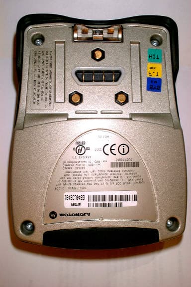
Click to zoom
Application Details
- Equipment Class
- DTS - Digital Transmission System
- Date of Grant
- Nov 05, 2002
- Application Purpose
- Original Equipment
- Date of Application
- Aug 17, 2002
- Equipment Note
- Hand held data terminal
- Frequency Range
- 2412.00000000 - 2462.00000000
- Company
- Motorola Solutions, Inc.
- Country
- United States
Documents & Files
Document Text
Text extracted from the exhibit documents filed with the FCC. Open a document above to read the original.
Users Manual
Applicant: Motorola, Inc. FCC ID: AZ489FT7001 Exhibit 8 Exhibit VIII. User Information and User Manual: 1.) User Card - 2 pages User Safety, Training, and General Information Operational Instructions and Training Guidelines 2.) User Manual - 59 pages UPScan Release 2.0 Loader/ Supervisor Training 68P02962C35-APlease retain for future use User Safety, Training, and General Information READ THIS IMPORTANT INFORMATION ON SAFE AND EFFICIENT OPERA- TION BEFORE USING YOUR MOTOROLA HANDHELD PORTABLE TERMINAL The information provided in this document supersedes the general safety informa- tion contained in user guides published prior to June 2001. For information regard- ing terminal use in a hazardous atmosphere please refer to the Factory Mutual (FM) Approval Manual Supplement or Instruction Card, which is included with terminal models that offer this capability. Compliance with RF Energy Exposure Standards Your Motorola terminal is designed and tested to comply with a number of national and international standards and guidelines (listed below) regarding human expo- sure to terminal frequency electromagnetic energy. This terminal complies with the IEEE (FCC) and ICNIRP exposure limit. In terms of measuring RF energy for com- pliance with the FCC exposure guidelines, your terminal radiates measurable RF energy only while it transmits data, not when it is receiving data. Your Motorola terminal complies with the following RF energy exposure stan- dards and guidelines: •United States Federal Communications Commission, Code of Federal Regula- tions; 47CFR part 2 sub-part J •American National Standards Institute (ANSI) / Institute of Electrical and Elec- tronic Engineers (IEEE) C95. 1-1992 •Institute of Electrical and Electronic Engineers (IEEE) C95.1-1999 Edition •International Commission on Non-Ionizing Radiation Protection (ICNIRP) 1998 •Ministry of Health (Canada) Safety Code 6. Limits of Human Exposure to Ter- minal frequency Electromagnetic Fields in the Frequency Range from 3 kHz to 300 GHz, 1999 •Australian Communications Authority Terminal communications (Electromag- netic Radiation - Human Exposure) Standard 2001 (applicable to wireless phones only) •ANATEL, Brasil Regulatory Authority, Resolution 256 (April 11, 2001) "addi- tional requirements for SMR, cellular and PCS product certification." Operational Instructions and Training Guidelines Body-worn Operation •Always place the terminal in a Motorola approved clip, holder, holster, case, attachment, or body harness for this product. Use of non-Motorola-approved accessories may exceed FCC RF exposure guidelines. •If you do not use a Motorola approved body-worn accessory, then ensure the terminal is kept 2.5 cm (one inch) from the body when transmitting. Antennas & Batteries •Use only Motorola approved supplied antenna or Motorola approved replace- ment antenna. Unauthorized antennas, modifications, or attachments could damage the terminal and may violate FCC regulations. •Use only Motorola approved, supplied batteries or Motorola approved replace- ment batteries. Use of non-Motorola-approved antennas or batteries may exceed FCC RF exposure guidelines. Approved Accessories For a list of Motorola approved accessories see the appendix of this user manual or visit the following website which lists approved accessories: Electromagnetic Interference/Compatibility Note: Nearly every electronic device is susceptible to electromagnetic in- terference (EMI) if inadequately shielded, designed, or otherwise configured for electromagnetic compatibility. Facilities To avoid electromagnetic interference and/or compatibility conflicts, turn off your ter- minal in any facility where posted notices instruct you to do so. Hospitals or health care facilities may be using equipment that is sensitive to external RF energy. Aircraft When instructed to do so, turn off your terminal when on board an aircraft. Any use of a terminal must be in accordance with applicable regulations per airline crew in- structions. Medical Devices Pacemakers The Advanced Medical Technology Association (AdvaMed) recommends that a minimum separation of 6 inches (15 centimeters) be maintained between a hand- held wireless terminal and a pacemaker. These recommendations are consistent with those of the U.S. Food and Drug Administration. HANDHELD PORTABLE TERMINAL EMERALD ab Persons with pacemakers should: •ALWAYS keep the terminal more than 6 inches (15 centimeters) from their pacemaker when the terminal is turned ON. •not carry the terminal in the breast pocket. •turn the terminal OFF immediately if you have any reason to suspect that inter- ference is taking place. Hearing Aids Some digital wireless terminals may interfere with some hearing aids. In the event of such interference, you may want to consult your hearing aid manufacturer to dis- cuss alternatives. Other Medical Devices If you use any other personal medical device, consult the manufacturer of your de- vice to determine if it is adequately shielded from RF energy. Your physician may be able to assist you in obtaining this information. Operational Warnings For Vehicles With an Air Bag Do not place a portable terminal in the area over an air bag or in the air bag deployment area. Air bags inflate with great force. If a portable terminal is placed in the air bag deployment area and the air bag inflates, the terminal may be propelled with great force and cause serious injury to occupants of the vehicle. Potentially Explosive Atmospheres Turn off your terminal prior to entering any area with a potentially explosive atmosphere, unless it is a terminal type especially qual- ified for use in such areas as "Intrinsically Safe" (for example, Fac- tory Mutual, CSA, UL, or CENELEC). Do not remove, install, or charge batteries in such areas. Sparks in a potentially explosive atmosphere can cause an explosion or fire resulting in bodily injury or even death. The areas with potentially explosive atmospheres referred to above include fuelin…
Text truncated - open the document above for the full version.
Attestation Statements
Exhibit 2 FCC Certification Report for the FCC ID: AZ489FT7001 EMERALD TERMINAL New Certification Exhibit II. Certification Data
Cover Letter(s)
Applicant : Motorola, Inc.FCC ID: AZ489FT7001 Exhibit 13 FCC Certification Report for the FCC ID: AZ489FT7001 EMERALD Terminal New Certification EXHIBIT XIII Cover Letters Cover Letter 1.) Certification action requested Cover Letter 2.) Request for Confidentiality under Part 0.459. Cover Letter 3.) Motorola Agent authorization letter allowing Rod Munro to sign FCC Form 731 on behalf of Motorola, Inc. Cover Letter 4.) Symbol Technologies, Inc. authorization to refer to data on file for FCC ID’s: H9PLA4137 and H9PCRS1 Motorola, Inc., 8000 W. Sunrise Blvd., Plantation, FL 33322 Page 1 of 2 Date: 25 th July 2002 Authorization & Evaluation Division Federal Communication Commission Laboratory 7435 Oakland Mills Road Columbia, MD 21046 Gentlemen: This letter authorizes Rod Munro, President of Spectrum Technology, Inc. to act for Motorola, Inc for the purpose of signing the FCC Form 731 electronically on behalf of Motorola, Inc. solely with respect to the DIAD III and Emerald products, FCC ID:AZ489FT7001 and FT7002. Also, to check ‘yes” in item 15 of the said form Section 5301 (Anti-Drug Abuse) certification. The applicant, Motorola, Inc., must certify that neither the applicant nor any party to the applicant is subject to denial of Federal benefits, that includes FCC benefits, pursuant to section 5301 of the Anti-Drug Abuse act of 1988, 21 USC Subpart 862 because of a conviction for possession or distribution of a controlled substance. See 47 CFR 1.2002(b) for the definition of a “party” for these purposes. Please contact me at 954.723.5793 if you require any additional information. Sincerely, /s/ Mike Ramnath FCC Liaison Email: [email protected]
External Photos
Applicant: Motorola, Inc.FCC ID: AZ489FT7001 Exhibit 3 EXHIBIT 3 EXTERNAL PHOTOS Emerald Terminal Front View of Terminal1 of 5 Applicant: Motorola, Inc.FCC ID: AZ489FT7001 Exhibit 3 Emerald Terminal Rear View of Terminal2 of 5 Applicant: Motorola, Inc.FCC ID: AZ489FT7001 Exhibit 3 Emerald Terminal Enlarged View of FCC Identifier and Location3 of 5 Applicant: Motorola, Inc.FCC ID: AZ489FT7001 Exhibit 3 Emerald Terminal Rear View of Terminal enlarged, battery removed4 of 5 Applicant: Motorola, Inc.FCC ID: AZ489FT7001 Exhibit 3 Emerald Terminal Rear View, battery removed from Terminal 5 of 5
ID Label/Location Info
Applicant: Motorola, Inc. FCC ID: AZ489FT7001 Exhibit 1 LIST OF EXHIBITS DESCRIPTION EXHIBITS REFERENCE I. Identification label Information 1 2.1033 (b) 7 & 2.925 & General Information 1A 1. Production Plans 2.1031 2. Application References N/A 3. Data submittal Procedure 4. Similar Certified Transmitter II. Certification Data 2 III. External Photographs 3 2.1033 (b) 7 IV. Block Diagrams (Circuit Diagrams 4 2.1033 (b) 5 V. Schematic Diagrams & Antenna Assembly 5 2.1033 (b) 5 VI. Supplemental Test Report 6 Original Test Report 6 * 2.1033 (b) 6 6 * 15.247 (a, b, c, g, h) VII. Test Set-up Procedures 7 * 2.1041 VIII. Instruction Manual 8 2.1033 (b) 3 IX. Internal Photographs 9 2.1033 (b) 7 X. Part List and Tune Up Procedures 10 N/A XI. RF Exposure Information 11 2.1093 XII. Operational Description 12 2.1033 (b) 1, 2, 4, 8 Antenna Requirements 12 15.203 1. Technical Characteristics 1 - 5 2. Application XIII. Cover Letter, Action Requested 13 Cover Letter, Authorization From Symbol 13 Cover Letter, Authorization to sign FCC Form 731 13 *Please refer to the Symbol Technologies, Inc. original Certification data for the following two Intentional Radiators used in the Emerald Terminal. 1.) FCC ID: H9PLA4137, IEEE 802.11, WLAN Compact Flash Card, Model: LA4137 & 2.) FCC ID: H9PCRS1, BLUETOOTH, Model: CRS1-10000-00 Please NOTE: Exhibits 4, 5 and 12 are requested to held confidential Applicant: Motorola, Inc. FCC ID: AZ489FT7001 Exhibit 1 EXHIBIT 1. FCC IDENTIFICATION LABEL ----- 47 CFR 2.1033(C) 11 LOCATION Back side of the transceiver unit chassis. MARKINGS (TEXT) Enlarged view of FCC portion of label: Applicant: Motorola, Inc. FCC ID: AZ489FT7001 Exhibit 1 Exhibit 1A. General Information --- 47 CFR 2.1031 and 2.1061. 1A.1. Production Plans -- Pursuant 47 CFR 2.1031 Quantity production is planned. 1A.2. Application References -- Pursuant 47 CFR 2.1061 Reference is made to the following Motorola "Application References" 1. Part 15.247 Intentional Radiators and their application 1A.3. Data Submittal Procedure Data located in Exhibit 6 is supplied in accordance with Part 2, Sub-part J and Part 15, Sub-part C of the Commissions’ rules and will be submitted electronically. 1A.4. Similar, currently Certified Intentional Radiator The Emerald Terminal is manufactured by Motorola, Inc. The Emerald contains within two Symbol Technologies, Inc. intentional radiators. 1.) FCC ID: H9PLA4137 for the WLAN Compact Flash Card, Model: LA4137 and 2.) FCC ID: H9PCRS1, Bluetooth module, Model: CRS1-10000-00 The two Intentional Radiators are used without any change or modification to the originally Certified hardware and would be considered identical as defined under Part 2.908. A new permanently attached internal antenna with a max. gain of –2 dBi, is used by both of these Intentional Radiators.
ID Label/Location Info
Applicant: Motorola, Inc. FCC ID: AZ489FT7001 Exhibit 1 LIST OF EXHIBITS DESCRIPTION EXHIBITS REFERENCE I. Identification label Information 1 2.1033 (b) 7 & 2.925 & General Information 1A 1. Production Plans 2.1031 2. Application References N/A 3. Data submittal Procedure 4. Similar Certified Transmitter II. Certification Data 2 III. External Photographs 3 2.1033 (b) 7 IV. Block Diagrams (Circuit Diagrams 4 2.1033 (b) 5 V. Schematic Diagrams & Antenna Assembly 5 2.1033 (b) 5 VI. Supplemental Test Report 6 Original Test Report 6 * 2.1033 (b) 6 6 * 15.247 (a, b, c, g, h) VII. Test Set-up Procedures 7 * 2.1041 VIII. Instruction Manual 8 2.1033 (b) 3 IX. Internal Photographs 9 2.1033 (b) 7 X. Part List and Tune Up Procedures 10 N/A XI. RF Exposure Information 11 2.1093 XII. Operational Description 12 2.1033 (b) 1, 2, 4, 8 Antenna Requirements 12 15.203 1. Technical Characteristics 1 - 5 2. Application XIII. Cover Letter, Action Requested 13 Cover Letter, Authorization From Symbol 13 Cover Letter, Authorization to sign FCC Form 731 13 *Please refer to the Symbol Technologies, Inc. original Certification data for the following two Intentional Radiators used in the Emerald Terminal. 1.) FCC ID: H9PLA4137, IEEE 802.11, WLAN Compact Flash Card, Model: LA4137 & 2.) FCC ID: H9PCRS1, BLUETOOTH, Model: CRS1-10000-00 Please NOTE: Exhibits 4, 5 and 12 are requested to held confidential Applicant: Motorola, Inc. FCC ID: AZ489FT7001 Exhibit 1 EXHIBIT 1. FCC IDENTIFICATION LABEL ----- 47 CFR 2.1033(C) 11 LOCATION Back side of the transceiver unit chassis. MARKINGS (TEXT) Enlarged view of FCC portion of label: Applicant: Motorola, Inc. FCC ID: AZ489FT7001 Exhibit 1 Exhibit 1A. General Information --- 47 CFR 2.1031 and 2.1061. 1A.1. Production Plans -- Pursuant 47 CFR 2.1031 Quantity production is planned. 1A.2. Application References -- Pursuant 47 CFR 2.1061 Reference is made to the following Motorola "Application References" 1. Part 15.247 Intentional Radiators and their application 1A.3. Data Submittal Procedure Data located in Exhibit 6 is supplied in accordance with Part 2, Sub-part J and Part 15, Sub-part C of the Commissions’ rules and will be submitted electronically. 1A.4. Similar, currently Certified Intentional Radiator The Emerald Terminal is manufactured by Motorola, Inc. The Emerald contains within two Symbol Technologies, Inc. intentional radiators. 1.) FCC ID: H9PLA4137 for the WLAN Compact Flash Card, Model: LA4137 and 2.) FCC ID: H9PCRS1, Bluetooth module, Model: CRS1-10000-00 The two Intentional Radiators are used without any change or modification to the originally Certified hardware and would be considered identical as defined under Part 2.908. A new permanently attached internal antenna with a max. gain of –2 dBi, is used by both of these Intentional Radiators.
Internal Photos
© 2001 PCTEST Lab SYMBOL FCC ID: H9PCRS1 NVLAP Lab Code: 100431-0 BLUETOOTH Transceiver & Wireless Ring Scanner © 2001 PCTEST Lab SYMBOL FCC ID: H9PCRS1 NVLAP Lab Code: 100431-0 BLUETOOTH Transceiver & Wireless Ring Scanner © 2001 PCTEST Lab SYMBOL FCC ID: H9PCRS1 NVLAP Lab Code: 100431-0 BLUETOOTH Transceiver & Wireless Ring Scanner © 2001 PCTEST Lab SYMBOL FCC ID: H9PCRS1 NVLAP Lab Code: 100431-0 BLUETOOTH Transceiver & Wireless Ring Scanner © 2001 PCTEST Lab SYMBOL FCC ID: H9PCRS1 NVLAP Lab Code: 100431-0 BLUETOOTH Transceiver & Wireless Ring Scanner © 2001 PCTEST Lab SYMBOL FCC ID: H9PCRS1 NVLAP Lab Code: 100431-0 BLUETOOTH Transceiver & Wireless Ring Scanner © 2001 PCTEST Lab SYMBOL FCC ID: H9PCRS1 NVLAP Lab Code: 100431-0 BLUETOOTH Transceiver & Wireless Ring Scanner
Internal Photos
© 2001 PCTEST Lab SYMBOL FCC ID: H9PLA4137 NVLAP Lab Code: 100431-0 DSSS Radio Card (PCMCIA)
Internal Photos
Applicant: Motorola, Inc.FCC ID: AZ489FT7001 Exhibit 9 Emerald Terminal Back Cover Removed1 of 6 Applicant: Motorola, Inc.FCC ID: AZ489FT7001 Exhibit 9 Emerald Terminal LCD assembly, LCD bottom frame is used as shield to the main board (left) H9PLA4137, WLAN Compact Flash Card, Model: LA4137 (upper right), Main Emerald board top view, Compact Flash Slot/Shied visible, small shield in upper right corner of board is Bluetooth Shield onm thop side of PCB only, (lower right) 2 of 6 Applicant: Motorola, Inc.FCC ID: AZ489FT7001 Exhibit 9 Emerald Terminal LCD Assembly Top View (upper left) Plastic Carrier Bottom View ( lower left) WLAN Compact Flash Card, Model: LA4137 Back View (upper right), Main Emerald Board Bottom View (lower right)3 of 6 Applicant: Motorola, Inc.FCC ID: AZ489FT7001 Exhibit 9 Emerald Terminal Front Cover (left side) Plastic Carrier Bottom View (right side)4 of 6 Applicant: Motorola, Inc.FCC ID: AZ489FT7001 Exhibit 9 Emerald Terminal Foil visible is the location of Antenna1, left side of center and Antenna 2 right side. The item below is the plastic antenna cover5 of 6 Applicant: Motorola, Inc.FCC ID: AZ489FT7001 Exhibit 9 Emerald Terminal Non metallic center frame antenna location & keypad board6 of 6 (Antenna coaxial cables visible through openning coming from the two antennas)
RF Exposure Info
Applicant: Motorola, Inc.FCC ID: AZ489FT7001 Exhibit 11 RF EXPOSURE INFORMATION: No SAR Report is submitted due to the total maximum power being less than 1.6mW.
RF Exposure Info
Applicant: Motorola Inc FCC ID: AZ489FT7001 Motorola Inc., 8000 W. Sunrise Blvd., Plantation, FL 33322 Date: 4 th November 2002 Miss Joe Dichoso Authorization & Evaluation Division Federal Communications Commission Laboratory 7435 Oakland Mills Road Columbia, MD 21046 Re: Form 731 Confirmation Number: EA417429 with FCC ID: AZ489FT7001. Dear Mr. Dichoso; Motorola Inc., 8000 West Sunrise Boulevard, Fort Lauderdale, Florida 33322, herein submits its response to your 31st October 2002 request for information on FCC ID: AZ489FT7001, EA417429 via correspondence number 24238. Q1) Filing still has duplicate and mislabeled exhibits, e.g., in External photos the exhibit "New Photos Wrist worn Waist worn Options" has only 2 pages antenna engr drawings. R1) The mislabeled and corrected Exhibits will be corrected as follows: Please delete the following eight files: 1. "New Exhibit 9 External Photos" (File size 410196) 2. "New Photos Wrist worn Waist worn Options." (File size 414509) 3. “New Exhibit 1 Table of Contents FCC ID label and General Information”. (File size 244737) The following four exhibits were left from the original submission which were not deleted and should be deleted: 4. “LA4137INTphotos (File size 787509) 5. Internal Photos (File size1216160) 6. Internal Pictures (File size757536) 7. Exhibit 9 Internal Photos (File size1547176) 8. “Excess Exhibit Deletion List" (File size 696053) The following files will be uploaded : 1. New Exhibit 9 Internal Photos 2. New Photos Wrist worn Waist worn Options will be uploaded under the RF Exposure Exhibit Q2) It would be useful to have more description and maybe timing diagrams to show that 2% duty factor is applicable. Explanation should be included or referenced in RF exposure exhibit. Applicant: Motorola Inc FCC ID: AZ489FT7001 Motorola Inc., 8000 W. Sunrise Blvd., Plantation, FL 33322 R2) Transmit Duty Cycle Time - Attached please find our calculation of the WLAN Transmit duty cycle time. The worst case result is transmit Duty cycle of less then 0.2%. (Please note, as explained in the attachment, that in the Emerald System the upper limit of the transmit duty Cycle is 0.2% and it cannot be exceeded). Since in Symbol's grant to FCC the Transmit Duty Cycle is 2% and in order to cover possible longer transmissions e.g.: system health check we have decided to define the transmit duty cycle of the Emerald System for FCC also as 2%. Q3) Exhibit "new test report" shows conducted power from HP438A Power Meter & HP8482H Power Sensor. How about submitting conducted with that when device is set at 2%. R3) Since the Emerald Terminal transmits for about 1mS every 500mS, the test equipment is limited in it’s capability in measuring the power at 1 mS. Therefore, we set the radio to special test mode for CW transmission (equivalent to 100% transmit duty cycle) and performed the power output measurement. The power at 2% duty cycle can be calculated from the results of the FCC Test Report, Exhibit VI, page 3. It is 0.858mW which is 2% of 42.92mW. Note: The WLAN radio is an OEM radio manufactured by Symbol Technologies. This radio has a FCC grant with a duty cycle of 2%, Motorola is not authorized to modify the radio or its operation. Q4) Output power will be listed on the grant as .59 mW for the Bluetooth and 43 mW for the WLAN. Please verify or retest. R4) Motorola agrees with the FCC that the output power of the Bluetooth as 0.59mW and the WLAN output power as 43mW. Q5) The Bluetooth test report needs correction. This needs to be filed under the DTS rules, unless you want to file a composite application (same identifier but filed as a FHSS system with additional information to be submitted.) Otherwise, file the Bluetooth as a DTS. Correct the test report by deleting pages 15-33 and correcting the frequency ranges in pages 1-3 to 2402-2480. R5) Per the attached interpretation memo from the FCC, the Bluetooth device cannot be filed as a DTS device. Therefore, we are suggesting that the Bluetooth Test Report, as filed and accepted by the FCC by Symbol Technologies, remain unchanged for this submission. FEDERAL COMMUNICATIONS COMMISSION Laboratory Division 7435 Oakland Mills Road Columbia, MD 21046 August 3, 2001 To all interested parties, The FCC Laboratory recently issued an interpretation that a frequency hopping spread spectrum (FHSS) transmitter could be approved under the waiver allowed for a digital transmission system (DTS) in the Further Notice of Proposed Rulemaking and Order in ET Docket No. 99-231 (FCC 01-158). After that interpretation was issued, we were asked to carefully review it for consistency with the proposal in the rulemaking. Applicant: Motorola Inc FCC ID: AZ489FT7001 Motorola Inc., 8000 W. Sunrise Blvd., Plantation, FL 33322 Based upon the text in this rulemaking, the Laboratory has reversed its recent interpretation. A FHSS transmitter may NOT be approved under the waiver permitted for a DTS device. Please disregard any information that you may have received informing you that a FHSS transmitter can be approved as a DTS device. The rulemaking that adopted the DTS provisions specifies that any communication system that has characteristics similar to a direct sequence spread spectrum (DSSS) system may be approved as a DTS device during the rulemaking proceeding. This was to allow new technologies like the Wi-Lan transmitter to be approved without delay. However, a FHSS transmitter clearly has characteristics very dissimilar to a DSSS transmitter. The Commission never intended the DTS waiver and approval process to apply to a FHSS transmitter. As was intended in the proceeding, this waiver was to apply only to a transmitter that employs spectrum characteristics similar to a DSSS system. Since a Bluetooth transmitter is classified as a FHSS device, it cannot be approved as a DTS device. Please contact Mr. Richard Fabina at [email protected] or 301-363-3021 if you have any questions regarding this reversal of our recent interpretation. If you h…
Text truncated - open the document above for the full version.
RF Exposure Info
!" 04 November 2002 Emerald System - 2% Transmit duty cycle calculation 1. Background (refer to the attached slides) 1.1. The Emerald System consists of: ! The Emerald Terminal. ! The Emerald Scanner (The Ring Scanner). ! The WLAN system. ! The UPS Host computer 1.2. The scanner flashes (maximum) twice every second searching for available Bar-Code label. Once the scanner identifies a valid Bar-Code Label, it opens its beam and reads the label. The Bar-Code data is transmitted to the Terminal via the Bluetooth link and than transmitted to the UPS host computer via the WLAN network. The host computer verifies and registers the package, and sends back acknowledge to the Terminal, which acknowledges the Scanner via the Bluetooth link, than the scanner can start the next scan. 2. Duty Cycle Calculation 2.1. Each Bar-code label consist of up to 18 characters which is 18 bytes of information = 180 bits 2.2. The overhead of the WLAN link is: ! TCP/IP – 40 Bytes per each transmission = 400 bits ! 802.11 protocol – 192uSec. 2.3. The WLAN baud rate is self-adjusted to 1,2,5,11Mbit during the 802.11 preamble time pending on the communication quality. The 802.11 overhead takes always 192uSec. 2.4. Table 1 summarizes the transmit duration of each Bar-Code label pending on the WLAN baud rate: l Communication Rate 1Mb/Sec 2Mb/Sec 5Mb/Sec 11Mb/Sec Bar- Code 180 bits 180 90 36 16.36 TCPIP Overhead 400 bits 400 200 80 36.36 802.11 protocol overhead 192uSec 192 192 192 192 Total uSec 772 482 308 244.72 Table 1 2.5. Conclusion: The maximum communication duration is 772uSec every 500msec. If we assume transmit duration of 1msec (worst case), than the DUTY CYCLE is 0.2%.
Test Report
Exhibit VI EXHIBIT VI. Supplemental Test Report For New Certification Of Two Previously Certified OEM Modules FCC ID: AZ489FT7001 EMERALD Terminal Certification Under Part 15.247 Prepared On Behalf Of Motorola, Inc. 8000 West Sunrise Blvd. Ft. Lauderdale, Florida 33322 Prepared By Spectrum Technology, Inc. 209 Dayton Street, Suite 205 Edmonds, WA 98020 425 771-4482 October 30, 2002 Applicant: Motorola, Inc. FCC ID: AZ489FT7001 Exhibit VI 2 Supplemental Test Report TABLE OF CONTENTS Cover Page 1 Table Of Contents 2 Exhibit 6A – Conducted RF Power Output (15.247 (b) 3 Equivalent Isotropic Radiated Power Exhibit 6G – Radiated Harmonics and Spurious Emissions 4 Exhibit 6G – Radiated Harmonics and Spurious Emissions 5 Note: Please refer to the original Certification exhibits uploaded with this new application for all of the original test report data for the following two Symbol Technologies, Inc. Intentional Radiators: 1.) FCC ID: H9PLA4137, IEEE 802.11(b), WLAN Compact Flash Card, Model: LA4137 and 2.) FCC ID: H9PCRS1, Bluetooth, Model: CRS1-10000-00 EXHIBIT 6A TEST: CONDUCTED RF POWER OUTPUT Applicant: Motorola, Inc. FCC ID: AZ489FT7001 Exhibit VI 3 FCC ID: AZ489FT7001 Applicant: Motorola, Inc. Model: F5071A Minimum Standard Specified: Part 15.247 is 1 Watt Test Results: The measured output power level on two samples shows compliance with the granted levels of: 0.1 Watt for WLAN and 0.001 Watt for the Bluetooth Authorization Procedure: Part 2.1046 Nominal Rated Output Power: WLAN 18 dBm conducted DSSS Bluetooth –2 dBm conducted FHSS Method of Measurement: 1. The two output power levels referenced above, had been preset during production for each model. 2. The peak output power was measured with HP438A Power Meter & HP8482H Power Sensor. 3. The measured channels cover the bottom, middle and top of the operational frequency range previously approved for each intentional radiator. Tabular Results of Conducted RF Output Power and EIRP WLAN S/N 184SCG0205 Sample 1 WLAN S/N 184SBW0578 Sample 2 Frequency (GHz) Power (mW) Power (dBm) Frequency (GHz)Power (mW) Power (dBm) 2.420 36.43 15.61 2.420 39.74 15.99 2.442 41.54 16.18 2.442 42.92 16.33 * * max. 2.460 35.33 15.48 2.460 33.67 15.27 The maximum WLAN EIRP (with antenna gain -2 dBi) is 14.44 dBm. Bluetooth S/N 184SCG0205 Sample 1 Bluetooth S/N 184SBW0578 Sample 2 Frequency (GHz) Power (mW) Power (dBm) Frequency (GHz)Power (mW) Power (dBm) 2.407 0.57440 -2.41 2.407 0.44510 -3.52 2.442 0.59340 -2.27* * max. 2.442 0.49717 -3.03 2.475 0.56702 -2.46 2.475 0.46146 -3.36 The maximum Bluetooth EIRP (with antenna gain -2 dBi) is –5.36 dBm. Applicant: Motorola, Inc. FCC ID: AZ489FT7001 Exhibit VI 4 EXHIBIT 6G TEST: RADIATED HARMONICS AND SPURIOUS EMISSIONS FCC ID: AZ489FT7001 Applicant: Motorola, Inc. Model: F5071A Minimum Standard Specified: Part 15.247 Test Results: Equipment complies with standard Authorization Procedure: Part 2.1053 Test Equipment Set Up: See Block Diagram in Exhibit 7 Frequency Range Observed: 0 to 24 GHz Operating Frequencies WLAN: 2.420, 2.442, & 2.460 GHz (2412 – 2462 GHz band) Rated Power Output WLAN: 0.1 Watt 18 dBm conducted WLAN FREQUENCY GHz Ant. Vert/ Horz Spectrum Analyzer Reading dBuV + Ant Factor - Amp Gain + Cable Loss = dBuV/m uV/m Ch. Low 2.420 V 82.83 28.37 22.3 2.6 91.50 37583 Ch. Mid 2.442 V 80.83 28.37 22.3 2.6 89.50 29853 Ch. High 2.460 V 74.17 28.37 22.3 2.6 82.84 13867 WLAN Frequency in GHz Harmonics observed Limit 74 dBuV/m Peak & 54 dBuV/m Average Ch. Low Fo 2.420 2Fo - 10Fo 4.840 – 24.200 At or < noise floor @3m All emissions < 54 dBuV/m or 500 uV/m Ch. Mid Fo 2.442 2Fo - 10Fo 4.884 – 24.420 At or < noise floor @3m All emissions < 54 dBuV/m or 500 uV/m Ch. High Fo 2.460 2Fo - 10Fo 4.920 – 24.600 At or < noise floor @3m All emissions < 54 dBuV/m or 500 uV/m All harmonic and spurious emissions were below the limit. A few of the lower harmonics were measurable at .5 m but, not a 3 m. An HP preamplifier was used during the measurements of the harmonics. A high pass filter was used to reduce the fundamental signal and avoid the possibility of overloading the front end of the analyzer. Test Notes: 1.) All harmonics in the restricted bands listed in Part 15.205 are below the Part 15.209 limit. 2.) No peak emissions above 1 GHz are more than 20 dB above the average limit. 3.) Peak measurements made with 1 MHz RBW & VBW, Average made with 1MHz RBW & 10 Hz VBW. 4.) During preliminary measurements at .5 meter the EUT was measured in 3 mutually orthogonal planes. The worst case found with the EUT on it’s right side so this position was used during final test made at 3 meters 5.) The EUT was powered with a fresh battery during the testing EXHIBIT 6G TEST: RADIATED HARMONICS AND SPURIOUS EMISSIONS Applicant: Motorola, Inc. FCC ID: AZ489FT7001 Exhibit VI 5 FCC ID: AZ489FT7001 Applicant: Motorola, Inc. Model: F5071A Minimum Standard Specified: Part 15.247 Test Results: Equipment complies with standard Authorization Procedure: Part 2.1053 Test Equipment Set Up: See Block Diagram in Exhibit 7 Frequency Range Observed: 0 to 24 GHz Operating Frequencies Bluetooth: 2.407, 2.442, & 2.475 GHz (2402 – 2480 GHz band) Rated Power Output Bluetooth: 0.001 Watt -2 dBm conducted Bluetooth FREQUENCY GHz Ant. Vert/ Horz Analyzer Reading dBuV + Ant Factor - Amp Gain + Cable Loss = dBuV/m uV/m Ch. Low 2.407 V 77.67 28.37 22.3 2.6 86.34 20749 Ch. Mid 2.442 V 74.33 28.37 22.3 2.6 81.0 14125 Ch. High 2.475 V 77.33 28.37 22.3 2.6 86.0 19952 Bluetooth Frequency in GHz Harmonics observed Limit 74 dBuV/m Peak & 54 dBuV/m Average Ch. Low Fo 2.407 2Fo - 10Fo 4.814 – 24.070 At or < noise floor @3m All emissions < 54 dBuV/m or 500 uV/m Ch. Mid Fo 2.442 2Fo - 10Fo 4.884 – 24.420 At or < noise floor @3m All emissions < 54 dBuV/m or 500 uV/m Ch. High Fo 2.475 2Fo - 10Fo 4.950 – 24.750 At or < noise floor @3m All emissions < 54 dBuV/m or 500 uV/m All harmonic and spurious emissions were below the noise floo…
Text truncated - open the document above for the full version.
Contact Information
Applicant
Deanna Zakharia(Regulatory Compliance Manager)
Technical Contact
Spectrum Technology IncRod A Munro
[email protected]425 771-4482
209 Dayton Street · Edmonds, Washington · United States
Non-Technical Contact
Spectrum Technology IncRod A Munro
[email protected]425 771-4482
Test Firm
Spectrum Technology Inc.Rod Munro
Technical Specifications
| # | Rule Parts | Frequency Range | Power Output |
|---|---|---|---|
| 2 | 15C | 2.41 GHz - 2.46 GHz | 43.00 mW |
Other Applications from Motorola Solutions, Inc.

AZ489FT4980
Sep 08, 2026Portable two way radio
Equipment Class
TNF - Licensed Non-Broadcast Transmitter Held to FaceAZ489FT4981
Aug 14, 2026Handheld Portable - TANAPA BPR 45 400-470 MHZ 4W NKP
Equipment Class
TNF - Licensed Non-Broadcast Transmitter Held to Face
AZ489FT7187
Jul 13, 2026Portable 2-Way Radio with Bluetooth, Bluetooth LE, WIFI 2.4GHz, WIFI 5GHz, LTE
Equipment Class
DSS - Part 15 Spread Spectrum TransmitterAZ499FT6031
May 11, 2026Operation Critical Wireless Earpiece PTT
Equipment Class
DSS - Part 15 Spread Spectrum Transmitter
AZ499FT5879
Dec 19, 20252-way Portable Radio with BT, BTLE, WIFI, NFC and LTE
Equipment Class
DSS - Part 15 Spread Spectrum Transmitter