AZ489FT7002Handheld or Belt mounted data terminal with two Sp
Motorola Solutions, Inc.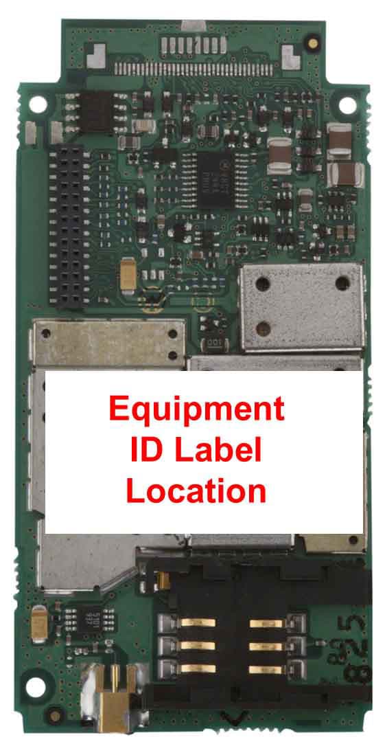
Click to zoom
Application Details
- Equipment Class
- PCT - PCS Licensed Transmitter worn on body
- Date of Grant
- Oct 01, 2002
- Application Purpose
- Original Equipment
- Date of Application
- Jul 31, 2002
- Equipment Note
- Handheld or Belt mounted data terminal with two Sp
- Frequency Range
- 1850.20000000 - 1909.80000000
- Company
- Motorola Solutions, Inc.
- Country
- United States
Documents & Files
Document Text
Text extracted from the exhibit documents filed with the FCC. Open a document above to read the original.
Users Manual
Applicant: Motorola, Inc. FCC ID: AZ489FT7002 Exhibit 8 Exhibit VIII. User Information and Manual: 1.) User Card - 2 pages User Safety Training and Safety Information Operational Instructions and Training Guidelines 2.) User Manual - 119 pages DIAD III Reference Guide 68P02963C77-O, March 2002 Safety Please retain for future use DIADIII Terminal with GPRS Radio-Modem User Safety, Training, and General Information READ THIS IMPORTANT INFORMATION ON SAFE ANDEFFICIENT OPERATION BEFORE USING YOUR MOTOROLAHANDHELD PORTABLE TERMINALThe information provided in this document supersedes the general safetyinformation contained in user guides published prior to June 2001. Forinformation regarding terminal use in a hazardous atmosphere please referto the Factory Mutual (FM) Approval Manual Supplement or Instruction Card,which is included with terminal models that offer this capability.Compliance with RF Energy Exposure StandardsYour Motorola terminal is designed and tested to comply with a number ofnational and international standards and guidelines (listed below) regardinghuman exposure to terminal frequency electromagnetic energy. This terminalcomplies with the IEEE (FCC) and ICNIRP exposure limits.Your Motorola terminal complies with the following RF energy exposurestandards and guidelines:• International Commission on Non-Ionizing Radiation Protection (ICNIRP) 1998 • United States Federal Communications Commission, Code of Federal Regulations; 47CFR part 2 sub-part J • American National Standards Institute (ANSI) / Institute of Electrical and Electronic Engineers (IEEE) C95. 1-1992 • Institute of Electrical and Electronic Engineers (IEEE) C95.1-1999Edition • Ministry of Health (Canada) Safety Code 6. Limits of Human Exposure to Terminal frequency Electromagnetic Fields in the Frequency Range from 3 kHz to 300 GHz, 1999 • Australian Communications Authority Terminal communications (Elec-tromagnetic Radiation - Human Exposure) Standard 1999 (applicable to wireless phones only) ï ANATEL, Brasil Regulatory Authority, Resolution 256 (April 11, 2001) "additional requirements for SMR, cellular and PCS product certifica-tion." OPERATIONAL INSTRUCTIONS AND TRAINING GUIDELINESBody-worn operation• Always place the terminal in a Motorola approved clip, holder, hol-ster, case, or body harness for this product. Use of non-Motorola- approved accessories may exceed FCC RF exposure guidelines. Antennas & Batteries• Use only Motorola approved supplied antenna or Motorolaapproved replacement antenna. Unauthorized antennas, modifica- tions, or attachments could damage the terminal and may violate FCCregulations. • Use only Motorola approved, supplied batteries or Motorolaapproved replacement batteries. Use of non-Motorola-approved antennas or batteries may exceed FCC RF exposure guidelines. APPROVED ACCESSORIESThe list of Approved Motorola accessories is given below:• DIADIII Battery FNN5101 • UPS Carrying Bag for DIADIII • DIADIII Handle (part of terminal) ELECTROMAGNETIC INTERFERENCE/COMPATIBILITYNote: Nearly every electronic device is susceptible to electromagnetic interference (EMI) if inadequately shielded, designed, or otherwiseconfigured for electromagnetic compatibility.FacilitiesTo avoid electromagnetic interference and/or compatibility conflicts, turn offyour terminal in any facility where posted notices instruct you to do so.Hospitals or health care facilities may be using equipment that is sensitive toexternal RF energy.AircraftWhen instructed to do so, turn off your terminal when on board an aircraft.Any use of a terminal must be in accordance with applicable regulations perairline crew instructions.Medical DevicesPacemakersThe Advanced Medical Technology Association (AdvaMed) recommends thata minimum separation of 6 inches (15 centimeters) be maintained between a 2963C77ODRAFT2.fm Page 1 Thursday, February 28, 2002 5:16 PM handheld wireless terminal and a pacemaker. These recommendations areconsistent with those of the U.S. Food and Drug Administration.Persons with pacemakers should:• ALWAYS keep the terminal more than 6 inches (15 centimeters) fromtheir pacemaker when the terminal is turned ON. • not carry the terminal in the breast pocket. • use the ear opposite the pacemaker to minimize the potential for inter-ference. • turn the terminal OFF immediately if you have any reason to suspectthat interference is taking place. Hearing AidsSome digital wireless terminals may interfere with some hearing aids. In theevent of such interference, you may want to consult your hearing aidmanufacturer to discuss alternatives.Other Medical DevicesIf you use any other personal medical device, consult the manufacturer ofyour device to determine if it is adequately shielded from RF energy. Yourphysician may be able to assist you in obtaining this information.Driver SafetyCheck the laws and regulations on the use of terminals in the area whereyou drive. Always obey them.When using your terminal while driving, please:• Givefullattentiontodrivingandtotheroad. • Use hands-free operation, if available. • Pull off the road and park before making or answering a call if driving conditions so require. OPERATIONAL WARNINGS For Vehicles With an Air Bag Do not place a portable terminal in the area over an air bag or in the airbag deployment area. Air bags inflate with great force. If a portableterminal is placed in the air bag deployment area and the air baginflates, the terminal may be propelled with great force and causeserious injury to occupants of the vehicle.Potentially Explosive AtmospheresTurn off your terminal prior to entering any area with a potentiallyexplosive atmosphere, unless it is a terminal type especially qualified for use in such areas as “Intrinsically Safe” (for example, FactoryMutual, CSA, UL, or CENELEC). Do not remove, install, or chargebatteries in such areas. Sparks in a potentially explosive atmospherecan cause an explosion or fire resulting in bodily injury or even death.The areas with potentially ex…
Text truncated - open the document above for the full version.
Users Manual
APPLICANT: MOTOROLA, INC.FCC ID: IHDT6AC1 EXHIBIT 8 INSTRUCTION MANUAL A preliminary draft copy of the Users Manual follows. RF exposure information is located in section 1.3. APPLICANT: MOTOROLA, INC.FCC ID: IHDT6AC1 Exhibit 8 1 D15 – Developer Guide – 1 st draft 1. Introduction Product description The D15 model Main application SAR Requirements. 2. Installation Mechanical description Connections 3. Pin description & main Functionality Pin description of connectors per model Different communication & application 4. Modes of Operation On/Off process include time diagram Voice connection Full flow control data call Soft GSM Operation 5. Design Consideration Power supply Antenna Data level (VOH, VOL) Flex cable & external SIM Connector Environmental 6 Testing & service How to test a unit in a voice call How to test a unit in a data call How to test a unit in a soft GSM call How to test RF features Desense test 7. Appendix 1st. Specification 2nd. A list of AT command 3rd. Desense test APPLICANT: MOTOROLA, INC.FCC ID: IHDT6AC1 Exhibit 8 2 1. Introduction 1.1 Product Specification – See in Appendix bellow. To add a note thal all the Data/Audio/SIM signals are compatible with D10 User Device D10 30 pin FC D15 User Device 36 pin FC 3 lines removed from each side 1.2 D15 Models: • D15 DV (DV= Data & Voice) Standard. APPLICANT: MOTOROLA, INC.FCC ID: IHDT6AC1 Exhibit 8 3 • D15 DV Slim • D15 DVG Slim (DVG= Data, Voice, GPS) • D15 DV Board only (Vertical version & Horizontal version) APPLICANT: MOTOROLA, INC.FCC ID: IHDT6AC1 Exhibit 8 4 1.3 SAR Requirements User Operation Do not operate your telephone when a person is within 8 inches (20 centimeters) of the antenna. A person or object within 8 inches (20 centimeters) of the antenna could impair call quality and may cause the phone to operate at a higher power level than necessary and expose that person to RF energy in excess of that established by the FCC RF Exposure Guidelines. IMPORTANT The telephone must be installed in a manner that provides a minimum separation distance of 20 cm or more between the antenna and persons to satisfy FCC RF exposure requirements for mobile transmitting devices. Antenna Installation IMPORTANT: To comply with the FCC RF exposure limits and satisfy the categorical exclusion requirements for mobile transmitters, the following requirements must be met: 1. A minimum separation distance of 20 cm must be maintained between the antenna and all persons. 2. The transmitter effective radiated power must be less than 3.0 Watts ERP (4.9 Watts or 36.9 dBm EIRP). This requires that the combination of antenna gain and feed line loss does not exceed 16 dBi. APPLICANT: MOTOROLA, INC.FCC ID: IHDT6AC1 Exhibit 8 5 2. Installation – See details in PRD. Configuration 1 with d10 mounting Configuration 1 Configuration 1 with narrower mounting with narrower mounting APPLICANT: MOTOROLA, INC.FCC ID: IHDT6AC1 Exhibit 8 6 Configuration 1 with narrower mounting Configuration 2 Configuration 2 APPLICANT: MOTOROLA, INC.FCC ID: IHDT6AC1 Exhibit 8 7 Configuration 2 Configuration 2 APPLICANT: MOTOROLA, INC.FCC ID: IHDT6AC1 Exhibit 8 8 APPLICANT: MOTOROLA, INC.FCC ID: IHDT6AC1 Exhibit 8 9 3. Pin description & main Functionality 3.1 Standard model & Slim model The available functionality in these models are the follow: Data & Voice (D10 Replacement & Slim) - Connections D15 Main Process. Uart #1 RS232 port User logic Power supplies Main PWR Audio Data port EXT_SIM DSC General Data purposes DSC bus 3.1.1 Function available in the user connector – 36 pin ZIF • VCC input. 3.0 to 6Vdc • Full RS232 - 9 pins. TXD, RXD, RTS,CTS,DSR,DTR,DCD,RI at 5V levels. • External SIM connections.SIM Clock, SIM reset, SIM I/O, SIM VCC,SIM PD • DSC bus.DSC_EN, Downlink, Uplink – Motorola proprietary us. • Audio In/Out.Audio out and On/Off in the same pin, audio in Signal and analog ground. • Man_Test line.Used to detect standard Motorola accessories. • TS line (mobport).Used to turn on the radio. • TX_EN line.This line is an indication when the radio is transmitting. Note: 1. The Audio Out line is used to send out the detected audio and as a toggle On/Off pin. APPLICANT: MOTOROLA, INC.FCC ID: IHDT6AC1 Exhibit 8 10 2. The TS line is used to turn On the units by any transaction from Low to high in this pin. 3.1.2 Connector pin out Pin #FunctionPin #Function 1 TX_EN19SIM I/O 2 N.U.20SIM CLK 3 N.U.21TS 4 TXD22DSC_EN 5 RXD23Down Link 6 DTR24Up Link 7 DCD25Analog Ground 8 RTS26Ground 9 CTS27Ground 10 DSR28Ground 11RI29Ground 12 Manual_Test30VCC 13 Audio In31VCC 14 On/Off + Audio Out32VCC 15 N.U. 33VCC 16SIM _PD 34NU 17SIM _VCC 35NU 18SIM_Reset 36NU APPLICANT: MOTOROLA, INC.FCC ID: IHDT6AC1 Exhibit 8 11 3.2 D15 with GPS The available functionality in this models are the follow: Data & Voice + GPS model - Connections GPS (M12) D15 Main Process. GPS Process. Uart #1 RS232 port User logic Power supplies GPS Ant PWR 1PPS RX Diff Main PWR Audio Data port EXT_SIM DSC GPS purposes General Data purposes DSC bus Reg 3V 3.2.1 Function available in the user connector – 36 pin ZIF • VCC input. 3.0 to 6Vdc • Full RS232 - 9 pins. TXD, RXD, RTS,CTS,DSR,DTR,DCD,RI at 5V levels. • External SIM connections.SIM Clock, SIM reset, SIM I/O, SIM VCC,SIM PD • DSC bus.DSC_EN, Downlink, Uplink – Motorola proprietary us. • Audio In/Out.Audio out and On/Off in the same pin, audio in Signal and analog ground. • Man_Test line.Used to detect standard Motorola accessories. • TS line (mobport).Used to turn on the radio. • TX_EN line.This line is an indication when the radio is transmitting. • GPSTXD & RXD in 3V levels, 1PPS, APPLICANT: MOTOROLA, INC.FCC ID: IHDT6AC1 Exhibit 8 12 RTCM, Antenna power Note: 1. The Audio Out line is used to send out the detected audio and as a toggle On/Off pin. 2. The TS line is used to turn On the units by any transaction from Low to high in this pin. 3. The GPS is mounted on top of theD15 and receive power from the D15 but it is a stand-alone unit. The GPS is working from 3V and th…
Text truncated - open the document above for the full version.
Attestation Statements
Exhibit 2 FCC Certification Report for the FCC ID: AZ489FT7002 DIAD III +GPRS TERMINAL New Certification Exhibit II. Certification Data
Attestation Statements
APPLICANT MOTOROLA INC.FCC ID:IHDT6AC1 EXHIBIT 2A SPECIFICATION COMPLIANCE STATEMENT The transceiver type IHDT6AC1 has been tested in accordance with the requirements contained in the appropriate Commission regulations . To the best of my knowledge , these tests were performed using measurement procedures consistent with industry or Commission standards and demonstrate that this equipment complies with the appropriate standards . Each unit manufactured imported or marketed , will conform to the sample tested within the variations that can be expected due to quantity production and testing on a statistical basis . I further certify that the necessary measurements were made at Motorola , located at 3 Kremenetski street, Tel-Aviv, Israel, with the exception of Radiated Spurious Emissions testing which took place at L.S. Compliance, Inc., located at W66 N220 Commerce Court, Cedarburg, Wisconsin. NAME:Reuven Konevky TITLE:Section Manager TCG Development Signed: (Signed) Date : April 14, 2000 APPLICANT MOTOROLA INC.FCC ID:IHDT6AC1 EXHIBIT 2B STATEMENT OF CERTIFICATION The technical data supplied with this application , was taken under my supervision is hereby duly certified . I also certify that this transmit equipment (FCC ID : IHDT6AC1) compliance with all applicable parts of the FCC Rules . The following is a statement of my qualifications : NAME:Eitan Kugman TITLE:Senior Engineer TCG Development Signed: (Signed) Date : April 14, 2000 I hereby certify that the above application was prepared under my direction and that to the best of my knowledge and belief , the facts set forth in this application and accompanying technical data are true and correct . NAME:Eli Sasson TITLE:Lead Engineer TCG Development Signed: (Signed) Date : April 14, 2000
Attestation Statements
APPLICANT: MOTOROLAFCC ID: IHDT6AC1 Exhibit 13 June 1, 2000 CONFIDENTIALITY REQUEST CONTAINED WITHIN Federal Communications Commission Authorization and Evaluation Division 7435 Oakland Mills Road Columbia, Maryland 21046 Re: Application for PCS Transceiver Certification Gentlemen: Application: Motorola, Inc., Personal Communications Sector, 600 N. U.S. Highway 45, Libertyville, Illinois 60048-1286 herein submits: Application for Equipment Authorization (FCC Form 731-October 1992 with integrated Fee Processing Form, Fee Codes EFT and EBC), application fee in the amount of $610, and Exhibits; for Certification of a PCS Transceiver, FCC ID: IHDT6AC1. Motorola is also the manufacturer of this equipment. Confidentiality: Pursuant to Section 0.459 of the Commission's rules (CFR 47), Motorola requests confidentiality for portions of the material contained in this application and that the identified material be withheld from public inspection following the grant of this authorization. This material contains Motorola's trade secrets and confidential information that Motorola does not customarily release to the public and which is otherwise not generally available to the public. Confidentiality is requested for the following exhibits: • Exhibit 4 Block Diagrams • Exhibit 5 Schematics • Exhibit 12 Operational Description Description: This equipment is a GSM Embedded Module, which operates in the 1900 MHz PCS band. It can transfer data or voice over a GSM network. Model differences are dependent upon housing and external connector variations. Contact Information: Please contact me by telephone at (847) 523-6167 or by e-mail ([email protected]), if there are questions or additional information needed concerning this filing. Regards, Andrew J. Bachler FCC Liaison Personal Communications Sector 600 N. U.S. Highway 45 Libertyville, IL 60048-5343 APPLICANT MOTOROLA INC.FCC ID:IHDT6AC1 EXHIBIT 2A SPECIFICATION COMPLIANCE STATEMENT The transceiver type IHDT6AC1 has been tested in accordance with the requirements contained in the appropriate Commission regulations . To the best of my knowledge , these tests were performed using measurement procedures consistent with industry or Commission standards and demonstrate that this equipment complies with the appropriate standards . Each unit manufactured imported or marketed , will conform to the sample tested within the variations that can be expected due to quantity production and testing on a statistical basis . I further certify that the necessary measurements were made at Motorola , located at 3 Kremenetski street, Tel-Aviv, Israel, with the exception of Radiated Spurious Emissions testing which took place at L.S. Compliance, Inc., located at W66 N220 Commerce Court, Cedarburg, Wisconsin. NAME:Reuven Konevky TITLE:Section Manager TCG Development Signed: (Signed) Date : April 14, 2000 APPLICANT MOTOROLA INC.FCC ID:IHDT6AC1 EXHIBIT 2B STATEMENT OF CERTIFICATION The technical data supplied with this application , was taken under my supervision is hereby duly certified . I also certify that this transmit equipment (FCC ID : IHDT6AC1) compliance with all applicable parts of the FCC Rules . The following is a statement of my qualifications : NAME:Eitan Kugman TITLE:Senior Engineer TCG Development Signed: (Signed) Date : April 14, 2000 I hereby certify that the above application was prepared under my direction and that to the best of my knowledge and belief , the facts set forth in this application and accompanying technical data are true and correct . NAME:Eli Sasson TITLE:Lead Engineer TCG Development Signed: (Signed) Date : April 14, 2000
Cover Letter(s)
Exhibit 13 FCC Certification Report for the FCC ID: AZ489FT7002 DIAD III +GPRS Radio Modem Hand Held Portable Terminal New Certification EXHIBIT XIII Cover Letters Cover Letter 1.) Certification action requested Cover Letter 2.) Request for Confidentiality under Part 0.459. Cover Letter 3.) Motorola Agent authorization letter allowing Rod Munro to sign FCC Form 731 on behalf of Motorola, Inc. Motorola, Inc., 8000 W. Sunrise Blvd., Plantation, FL 33322 Page 1 of 2 Date: 25 th July 2002 Authorization & Evaluation Division Federal Communication Commission Laboratory 7435 Oakland Mills Road Columbia, MD 21046 Gentlemen: This letter authorizes Rod Munro, President of Spectrum Technology, Inc. to act for Motorola, Inc for the purpose of signing the FCC Form 731 electronically on behalf of Motorola, Inc. solely with respect to the DIAD III and Emerald products, FCC ID:AZ489FT7001 and FT7002. Also, to check ‘yes” in item 15 of the said form Section 5301 (Anti-Drug Abuse) certification. The applicant, Motorola, Inc., must certify that neither the applicant nor any party to the applicant is subject to denial of Federal benefits, that includes FCC benefits, pursuant to section 5301 of the Anti-Drug Abuse act of 1988, 21 USC Subpart 862 because of a conviction for possession or distribution of a controlled substance. See 47 CFR 1.2002(b) for the definition of a “party” for these purposes. Please contact me at 954.723.5793 if you require any additional information. Sincerely, /s/ Mike Ramnath FCC Liaison Email: [email protected]
External Photos
Applicant: Motorola, Inc.FCC ID: AZ489FT7002 Exhibit 3 DIAD III +GPRS Terminal Front View of DIAD III +GPRS Terminal1 of 4 Applicant: Motorola, Inc.FCC ID: AZ489FT7002 Exhibit 3 DIAD III +GPRS Terminal Back View of DIAD III +GPRS Terminal2 of 4 Applicant: Motorola, Inc.FCC ID: AZ489FT7002 Exhibit 3 DIAD III +GPRS Terminal Enlarged View of FCC Identifier Label3 of 5 Applicant: Motorola, Inc.FCC ID: AZ489FT7002 Exhibit 3 DIAD III +GPRS Terminal Top End of Bottom View Of The DIAD III +GPRS Terminal4 of 5 Applicant: Motorola, Inc.FCC ID: AZ489FT7002 Exhibit 3 DIAD III +GPRS Terminal Battery and Bottom End View of DIAD III +GPRS Terminal5 of 5
External Photos
APPLICANT: MOTOROLA, INC. FCC ID: IHDT6AC1 EXHIBIT 3A Typical Non-Housed Unit (Bottom View) Typical Non-Housed Unit (Top View Showing ID Label on Shields) APPLICANT: MOTOROLA, INC. FCC ID: IHDT6AC1 EXHIBIT 3B Typical Housed Unit (Bottom View) Typical Housed Unit (Top View Showing ID Label )
ID Label/Location Info
Applicant: Motorola Inc. FCC ID: AZ489FT7002 Exhibit 1 1 LIST OF EXHIBITS DESCRIPTIO NEXHIBITSREFERENCE I.Identification label Information12.1033 (c)11 & 2.925 & General Information1A 1. Production Plans2.1031 2. Application References2.1061 3. Data submittal Procedure 4. Similar Certified Transmitter II.Certification Data2 III.External Photographs32.1033 (c)12 IV.Block Diagrams (Circuit Diagrams)42.1033 (c)10 V.Schematic Diagrams52.1033 (c)10 VI.Supplemental Test Report6 1. Data Index6 2. RF Output Data6A 2.1046 3. Modulation Characteristics*2.1047 4. Occupied Bandwidth*2.1049 5. Conducted Spurious Emissions*2.1051 6. Radiated Spurious Emissions6G2.1053 7. Frequency Stability* (Temperature & Supply Voltage) 2.1055 VII.Test Set-up Procedures72.1041 VIII.Instruction Manual82.1033 (c)3 IX.Internal Photographs92.1033 (c)12 X.Part List and Tune Up Procedures102.1033 (c)9 XI.RF Exposure Information112.1093 XII.Operational Description122.1033 (c)1, 2, 4, 5, 6, 7 2.1033 (c)8, 13 * 1. Technical Characteristics 1 - 5 2. Application XIII. Cover Letter13 * Please refer to the original Certification data uploaded with this application previously on file for the FCC ID: IHDT6AC1 . Note: Exhibits 4, 5, and 12 are requested to be held Confidential. Applicant: Motorola Inc. FCC ID: AZ489FT7002 Exhibit 1 2 EXHIBIT 1. IDENTIFICATION LABEL ----- 47 CFR. 2.1033(C) 11 LOCATION Back side center label of the DIAD III chassis. TYPE The label is a paper polyester film laminate with a pressure sensitive adhesive backing .05 mm thick. Enlarged view of FCC ID LABEL Applicant: Motorola Inc. FCC ID: AZ489FT7002 Exhibit 1 3 FCC ID Label Location Center label: Red top and black lower background is FCC ID label Applicant: Motorola Inc. FCC ID: AZ489FT7002 Exhibit 1 4 Exhibit 1A. General Information --- 47 CFR 2.1031 and 2.1061. 1A.1. Production Plans -- Pursuant 47 CFR 2.1031 Quantity production is planned. 1A.2. Application References -- Pursuant 47 CFR 2.1061 Reference is made to the following Motorola "Application References" 1. Land Mobile Products and their application 1A.3. Data Submittal Procedure Data located in Exhibit 6 is supplied in accordance with Part 2, Sub-part J and Part 24, Sub-parts I and J of the Commissions’ rules and will be submitted electronically. 1A.4. Similar, currently Type Accepted Transmitter The DIAD III, Model: F4413A, manufactured by Motorola Inc., contains within the Motorola, Inc. Model: SUG2228AA, OEM module presently Certified under the FCC ID:IHDT6AC1. The transmitters are identical as defined under Part 2.908.
Internal Photos
Applicant: Motorola, Inc.FCC ID: AZ489FT7002 Exhibit 9 DIAD III +GPRS Terminal Top Cover/Keyboard Removed1 of 12 Applicant: Motorola, Inc.FCC ID: AZ489FT7002 Exhibit 9 DIAD III +GPRS Terminal Inside View All Shields In Place2 of 12 Applicant: Motorola, Inc.FCC ID: AZ489FT7002 Exhibit 9 DIAD III +GPRS Terminal Antenna Front View3 of 12 Applicant: Motorola, Inc.FCC ID: AZ489FT7002 Exhibit 9 DIAD III +GPRS Terminal Antenna Back View4 of 12 Applicant: Motorola, Inc.FCC ID: AZ489FT7002 Exhibit 9 DIAD III +GPRS Terminal Digital Board Top Foil Shield Removed, Ant. Location Lower Right 5 of 12 Applicant: Motorola, Inc.FCC ID: AZ489FT7002 Exhibit 9 DIAD III +GPRS Terminal Digital Board Bottom Foil Shield In Place6 of 12 Applicant: Motorola, Inc.FCC ID: AZ489FT7002 Exhibit 9 DIAD III +GPRS Terminal Digital Board Bottom Foil Shield Removed7of 12 Applicant: Motorola, Inc.FCC ID: AZ489FT7002 Exhibit 9 DIAD III +GPRS Terminal G18 Radio Interface Board Shield Removed with8 of 12 Transceiver Module FCC ID: IHDT6AC1 located below it Applicant: Motorola, Inc.FCC ID: AZ489FT7002 Exhibit 9 DIAD III +GPRS Terminal Transceiver G18 Module View FCC ID: IHDT6AC1 & 9 of 12 Bottom of G18 Radio Interface Board (lower pcb with shields) Applicant: Motorola, Inc.FCC ID: AZ489FT7002 Exhibit 9 DIAD III +GPRS Terminal Bottom View Transceiver Cover Shield10 of 12 Applicant: Motorola, Inc.FCC ID: AZ489FT7002 Exhibit 9 DIAD III +GPRS Terminal Bottom View of G18 Transceiver PCB and top cover shield 11 of 12 Applicant: Motorola, Inc.FCC ID: AZ489FT7002 Exhibit 9 DIAD III +GPRS Terminal Bar Code Reader Assembly12 of 12
Internal Photos
APPLICANT: MOTOROLA, INC. FCC ID: IHDT6AC1 EXHIBIT 9 Typical Unit (Bottom View Shields Removed) Typical Unit (Top View Shields Removed) Note: External connector type varies depending upon model
RF Exposure Info
Certificate Number: 1449-02 CGISS EME Test Laboratory 8000 West Sunrise Blvd Fort Lauderdale, FL. 33322 S.A.R. EME Compliance Test Report Attention: Federal Communication Commission Date of Report: May 22, 2002 Report Revision: Rev. O Device Manufacturer: Motorola Device Description: Wireless Data Device with GPRS FCC ID: AZ489FT7002 Device Model: F4413A Test Period: Test Engineer: Author: 1/3/02 –1/10/02 Stephen Whalen Sr. Test En gineer Michael Sailsman EME Regulatory Affairs Liaison Note: Based on the information and the testing results provided herein, the undersigned certifies that when used as stated in the operating instructions supplied, said product complies with the national and international reference standards and guidelines listed in section 2.0 of this report. Ken Enger ____________________________________________________________ _________________________ Senior Resource Manager, Product Safety and EME Director Date Approved Form-SAR-Rpt-B9 Page 1 of 65 TABLE OF CONTENTS 1.0 Introduction 2.0 Reference Standards and Guidelines 3.0 Description of Test Sample 3.1 Test Signal 3.2 Test Output Power 4.0 Description of Test Equipment 4.1 Description of S.A.R. Measurement System 4.2 Description of Phantom 4.2.1 Body Phantom 4.3 Simulated Tissue Properties 4.3.1 Type of Simulated Tissue 4.3.2 Simulated Tissue Composition 4.4 Test condition 5.0 Description of Test Procedures 5.1 Device Test Positions 5.1.1 Abdomen 5.2 Probe Scan Procedures 6.0 Measurement Uncertainty 7.0 S.A.R. Test Results 7.1 S.A.R. results at the abdomen 7.2 Peak S.A.R. location 8.0 Conclusion Form-SAR-Rpt-B9 Page 2 of 65 TABLE OF CONTENTS (Cont.) Appendix A: Power Slump Data Appendix B: Data Results Appendix C: Dipole System Performance Check Results Appendix D: Calibration Certificates Appendix E: Illustration of Body-worn Accessories REVISION HISTORY Date Revision Comments 5/22/02 O Initial release Form-SAR-Rpt-B9 Page 3 of 65 1.0 Introduction This report details the utilization, test setup, test equipment, and test results of the Specific Absorption Rate (S.A.R.) measurements performed at the CGISS EME Test Lab for the hand held data terminal with GPRS, model number F4413A, FCC ID AZ489FT7002. The applicable exposure environment is General Population/Uncontrolled. The test results included herein represent the highest S.A.R. levels applicable to this product and clearly demonstrate compliance with FCC General Population/Uncontrolled RF Exposure limits of 1.6 mW/g per the requirements of 47 CFR 2.1093(d). 2.0 Reference Standards and Guidelines This product is designed to comply with the following national and international standards and guidelines. • United States Federal Communications Commission, Code of Federal Regulations; 47CFR part 2 sub-part J • American National Standards Institute (ANSI) / Institute of Electrical and Electronic Engineers (IEEE) C95. 1-1992 • Institute of Electrical and Electronic Engineers (IEEE) C95.1-1999 Edition • International Commission on Non-Ionizing Radiation Protection (ICNIRP) 1998 • Ministry of Health (Canada) Safety Code 6. Limits of Human Exposure to Terminal frequency Electromagnetic Fields in the Frequency Range from 3 kHz to 300 GHz, 1999 • Australian Communications Authority Terminal communications (Electromagnetic Radiation - Human Exposure) Standard 2001 • ANATEL, Brazil Regulatory Authority, Resolution 256 (April 11, 2001) "additional requirements for SMR, cellular and PCS product certification." Form-SAR-Rpt-B9 Page 4 of 65 3.0 Description of Test Sample Model F4413A is a hand held or body worn data terminal with GPRS functionality. The terminal’s intended use will be for data acquisition during delivery of packages. The data terminal is operated while being held by its handle, within a recommended user’s holster, or while placed on top of a parcel. The device transmits and receives data exclusively using a radio modem data terminal (g18) that operates on the GPRS communication network. The device transmits and receives data intermittently. The transmission bursts have an average duration of approximately three seconds. Transmission and reception of data can occur without user initiation. The total number of transmission events during a normal day is expected to range between 40 and 150. The device is intended to be in a fixed location in a vehicle when not being operated by the user and is intended to be operated any where inside the vehicle once the vehicle is stationary. The maximum power outputs and the transmit frequency ranges for the data terminal are 2W pulsed averaged for EGSM (880.2 – 914.8MHz), 1W pulsed averaged for DCS 1800 (1710 – 1784.8MHz) and PCS 1900 (1850.2 – 1909.8MHz). All bands operate using TDMA 1:8 transmit duty cycle. Form-SAR-Rpt-B9 Page 5 of 65 The data terminal is offered with the following options and accessories: Batteries FNN5101A 7.2V/ 2400 mAhr Lithium Ion Rechargeable battery Body-Worn Accessories UPS192010 UPS personal Carrying bag for Europe only Other FPN1520A Battery Charger 3.1 Test Signal Test Signal mode Test ModeX Base Station Simulator Transmission Mode CW Native Transmission TDMA 1:8 X EGSM, DCS, PCS X 3.2 Test Output Power This data terminal uses an inaccessible internal antenna. For this reason a power vs. time characteristic curve was measured for a time interval greater than the expected S.A.R. measurement duration. This curve is then used to determine the power slump characteristics at the actual end time of the S.A.R. measurement. Tables of the characteristic curves for each mode of operation can be found in Appendix A. Form-SAR-Rpt-B9 Page…
Text truncated - open the document above for the full version.
Contact Information
Applicant
Deanna Zakharia(Regulatory Compliance Manager)
Technical Contact
Spectrum Technology, Inc.Rod A Munro
[email protected]425 771-4482
209 Dayton Street · Edmonds, Washington · United States
Non-Technical Contact
Spectrum Technology, Inc.Rod A Munro
[email protected]425 771-4482
Test Firm
Spectrum Technology Inc.Rod Munro
Technical Specifications
| # | Rule Parts | Frequency Range | Power Output | Emission | Tolerance |
|---|---|---|---|---|---|
| 1 | 24E | 1.85 GHz - 1.91 GHz | 980.00 mW | 250KGXW | 0.1000000000 ppm |
Other Applications from Motorola Solutions, Inc.

AZ489FT4980
Sep 08, 2026Portable two way radio
Equipment Class
TNF - Licensed Non-Broadcast Transmitter Held to FaceAZ489FT4981
Aug 14, 2026Handheld Portable - TANAPA BPR 45 400-470 MHZ 4W NKP
Equipment Class
TNF - Licensed Non-Broadcast Transmitter Held to Face
AZ489FT7187
Jul 13, 2026Portable 2-Way Radio with Bluetooth, Bluetooth LE, WIFI 2.4GHz, WIFI 5GHz, LTE
Equipment Class
DSS - Part 15 Spread Spectrum TransmitterAZ499FT6031
May 11, 2026Operation Critical Wireless Earpiece PTT
Equipment Class
DSS - Part 15 Spread Spectrum Transmitter
AZ499FT5879
Dec 19, 20252-way Portable Radio with BT, BTLE, WIFI, NFC and LTE
Equipment Class
DSS - Part 15 Spread Spectrum Transmitter