AZ489FT7005Models: F4420A and F4425
Motorola Solutions, Inc.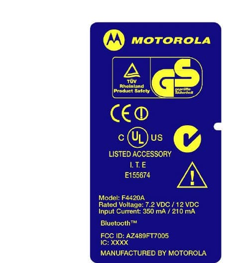
Click to zoom
Application Details
- Equipment Class
- DSS - Part 15 Spread Spectrum Transmitter
- Date of Grant
- Feb 18, 2003
- Application Purpose
- Original Equipment
- Date of Application
- Feb 18, 2003
- Equipment Note
- Models: F4420A and F4425
- Frequency Range
- 2402.00000000 - 2480.00000000
- Company
- Motorola Solutions, Inc.
- Country
- United States
Documents & Files
Document Text
Text extracted from the exhibit documents filed with the FCC. Open a document above to read the original.
Users Manual
Applicant: Motorola, Inc. FCC ID: AZ489FT7005 Exhibit 8 Exhibit VIII User Information and User Manual 1) User Card/Booklet - 2 pages, contains important information for safe usage and RF energy awareness and control 2) User Manual PowerPad Portable Data Terminal - 33 PDF pages total, 22 numbered pages Please find the information required by Part 15.19, 15.21 & 15.105 on pages iii & iv of the Owners Manual or pages 8 & 9 of this PDF file. Note: Items 1 & 2 above follow this cover page 68P029 66C56- B Ple ase retain for fut ure u se BEFORE USING THIS RADIO TERMINAL, READ THIS BOOKLET WHICH CONTAINS IMPORTANT OPERATING INSTRUCTIONS FOR SAFE USAGE AND RF ENERGY AWARENESS AND CONTROL INFORMATION FOR COMPLIANCE WITH RF ENERGY EXPOSURE LIMITS IN APPLICABLE NATIONAL AND INTERNATIONAL STAN-DARDS. The information provided in this docume nt supersedes information con tained in user guides publi shed prior to February 200 3 . For radio terminals that have been approved as intrinsically safe, read the instruc-tions and information on intrinsic safety in this booklet. Caution: changes or modifications made in the radio terminal, not express ly ap- proved by Motorola, will void the user's authority to operate the equipment. This radio terminal is intended for use in a business environment. Federal Communication Commission Regulations: The FCC established limits for safe exposure to radio frequency (RF) emissions from portable two-way radio terminals . The FCC requires manufact urers to dem onst rate compliance wi th RF exposure limits before portable two-way radio terminals can be marke t- ed in the U.S. This user safety booklet includes useful information about RF exposure and helpful instructions on how to control your RF exposures. Your Motorola two-way radio terminal is designed and tested to comply with a num-ber of national and international standards and guidelines (listed below) regarding human exposure to radio frequency electromagnetic energy. This radio terminal complies with the IEEE (FCC) and ICNIRP exposure limits for general population exposure RF exposure environment. This radio terminal complies with Part 15 of the FCC Rules. Operation is subject to the following two conditions: (1) this device may not cause harmful interference, and (2) this device must accept any interference re-ceived, including interference that may cause undesired operation.In terms of measuring RF energy for compliance with the FCC exposure guidelines, your radio terminal radiates measurable RF energy only while it is transmitting, not when it is receiving or in standby mode. Your Motorola two-way radio terminal complies with the following RF energy exposure standards and guidelines: • United States Federal Communications Commission, Code of Federal Regula- tions; 47CFR part 2 sub-part J • American National Standards Institute (ANSI) / Institute of Electrical and Elec- tronic Engineers (IEEE) C95. 1-1992 • Institute of Electrical and Electronic Engineers (IEEE) C95.1-1999 Edition• International Commission on Non-Ionizing Radiation Protection (ICNIRP) 1998 • Ministry of Health (Canada) Safety Code 6. Limits of Human Exposure to Radio frequency Electromagnetic Fields in the Frequency Range from 3 kHz to 300 GHz, 1999 • Australian Communications Authority Radio communications (Electromagnetic Radiation - Human Exposure) Standard 2001. • ANATEL, Brasil Regulatory Authority, Resolution 256 (April 11, 2001) "addi- tional requirements for SMR, cellular and PCS product certification." Compliance and Control Guidelines and Operating Instructions for portable two-way radio terminals To control your expos ure and ensu re compliance wi th the applicable expo sure environment limits a lw ays a dhere to the foll owi ng Procedures. • If you are not using a body-worn accessory and are not using the radio termi- 2-WAY POR TABLE RADIO TERMINAL PowerPad ab nal in the intended use position, then ensure the antenna and the r adio terminal are k ept 2.5 cm (one inc h) from the body when in use. Keeping t he radio terminal at a proper distance is important becau se of RF exposures decrease with distance from the antenna. • Use only Motorola approved supplied or replacement batteries, and accesso- ries. Use of non-Motorola-approved, batteries and accessories may exceed FCC RF exposure guidelines. For additional information on RF exposure awareness information, visit the following Motorola website: www.mot.com/rfhealth. Electromagnetic Interference/CompatibilityNote:Nearly every electronic device is susceptible to electromagnetic interference (EMI) if inadequately shielded, designed, or otherwise configured for electromagnet-ic compatibility.FacilitiesTo avoid electromagnetic interference and/or compatibility conflicts, turn off your ra-dio terminal in any facility where posted notices instruct you to do so. Hospitals or health care facilities may be using equipment that is sensitive to external RF energy.AircraftWhen instructed to do so, turn off your radio terminal when on board an aircraft. Any use of a radio terminal must be in accordance with applicable regulations per airline crew instructions.Medical DevicesPacemakersThe Advanced Medical Technology Association (AdvaMed) recommends that a minimum separation of 6 inches (15 centimeters) be maintained between a hand-held wireless radio terminal and a pacemaker. These recommendations are consis-tent with those of the U.S. Food and Drug Administration.Persons with pacemakers should: • ALWAYS keep the radio terminal more than 6 inches (15 centimeters) from their pacemaker when the radio terminal is turned ON. • Do not carry the radio terminal in the breast pocket.• Turn the radio terminal OFF immediately if you have any reason to suspect that interference is taking place. Hearing AidsSome digital wireless radio terminals may interfere with some hearing aids. In the event of such interference, you may want to consult your hearing aid manufacturer to discuss alternatives.Other Medical Dev…
Text truncated - open the document above for the full version.
Attestation Statements
Applicant: Motorola, Inc.FCC ID: AZ489FT7005 Exhibit 2 FCC Certification Report for the FCC ID: AZ489FT7005 PowerPad Terminal New Certification Exhibit 2 - Certification Data
Cover Letter(s)
Northwest EMC TCB Compliance Opinion Revision 1/3/03 SPTE0007 Information about the Applicant Company Name Motorola, Inc. Address 8000 West Sunrise Blvd City, State, Zip Ft. Lauderdale Requested By Mike Ramnath Job Number SPTE0007 Model F4420A and F4425 FCC ID AZ489FT7005 Agent Rod Munro – Spectrum Technology, Inc. Approval Type Certification Equipment Type FHSS (Bluetooth radio) Rule Part 47CFR15.247 Overview Certification is sought for Motorola’s PowerPad Model: F4420A and identical Model: F4425. The two models are “identical” as defined by Part 2.908, with cosmetic appearance changes only. Both are ruggedized Portable Digital Assistants (PDAs) which contain a new Bluetooth TM Intentional Radiator, not previously approved under 47 CFR 15.247. The Bluetooth TM radio is intended for short distance communication with peripheral devices. It supports multimedia and audio using a built-in microphone, speaker and buzzer. Recommendation All items have been resolved and completed to my satisfaction; therefore I recommend this application for approval. February 18, 2003 _______________________________ ________________ Gregory V. Kiemel, Director of Engineering Date Northwest EMC TCB Compliance Opinion Revision 1/3/03 SPTE0007 Findings and Resolution Item #1 User Card stated for “occupational / controlled applications” Resolution User Card and Manual exhibit was updated to reflect general population exposure. Item #2 Location of FCC ID label was unclear Resolution External Photos exhibit was updated to more clearly show the location of the FCC ID label Item #3 In the test report, the description for occupied bandwidth referenced an older version of Part 15. Resolution The test report exhibit was updated to reflect the latest version of Part 15 (8-23-2002) Item #4 A non-standard test method was used to measure power spectral density. Resolution The test report exhibit was updated to delete the power spectral density test data. The applicant requested that the subject device be filed as a FHSS. The applicant conferred with Joe Dichoso of the FCC who confirmed this was acce ptable. Item #5 The carrier was not modulated during testing. Resolution The test report exhibit was updated with new test data taken with the carrier modulated. Item #6 The list of measurement equipment did not show test equipment capable of radiated emissions scans up to the 10 th harmonic of the radio’s transmit frequency. Resolution The test report exhibit was updated with new test data taken with measurement equipment cable of radiated emissions scans up to 22 GHz. The applicant conferred with Joe Dichoso of the FCC who granted a “one time exception” and deemed 22 GHz an acceptable upper frequency limit. (See FCC email filed with this application). Item #7 No radiated emission data was provided in the 2.4835 GHz to 2.5 GHz restricted band while the radio was transmitting at the highest possible channel. Resolution The test report exhibit was updated with new test data taken in the 2.4835 GHz to 2.5 GHz restricted band while the radio was transmitting at the highest possible channel. Northwest EMC TCB Compliance Opinion Revision 1/3/03 SPTE0007 Opinion Specification Requirements Description 47 CFR 15.247(b)(5) and 2.1093 RF Exposure Opinion: The Equipment meets the intent specified by the requirements listed above. Discussion: The Applicant has demonstrated compliance in the form of an Exhibit. Reference: Exhibit 11 Specification Requirements Description 47 CFR 15.247 Occupied Bandwidth Opinion: The Equipment meets the intent specified by the requirements listed above. Discussion: The Applicant has submitted test results in the form of a test report. According to the FCC’s Interpretations Database, “Frequency hoppers in the 2.4 GHz band are required to use a minimum of 15 non-overlapping channels. The hopping channel bandwidth can be wider than 1 MHz as long as the channels do not overlap and all emissions stay within the 2400-2483.5 MHz band. (ref. email sent to [email protected] 10/08/2002)” The subject radio uses more than 15 hopping channels, none of which overlap. The maximum 20 dB occupied bandwidth is less than 1 MHz. Reference: Exhibit 6 Specification Requirements Description 47 CFR 15.247(b)(1) Power Output Opinion: The Equipment meets the intent specified by the requirements listed above. Discussion: The Applicant has submitted test results in the form of a test report. Reference: Exhibit 6 Specification Requirements Description 47 CFR 15.247(c) Spurious Emissions, Antenna Conducted Opinion: The Equipment meets the intent specified by the requirements listed above. Discussion: The Applicant has submitted test results in the form of a test report. Reference: Exhibit 6 Northwest EMC TCB Compliance Opinion Revision 1/3/03 SPTE0007 Specification Requirements Description 47 CFR 15.247(c), 15.205, & 15.209 Spurious Emissions, Radiated Emissions Opinion: The Equipment meets the intent specified by the requirements listed above. Discussion: The Applicant has submitted test results in the form of a test report. Reference: Exhibit 6 Specification Requirements Description 47 CFR 15.207 AC Powerline Conducted Emissions Opinion: The Equipment meets the intent specified by the requirements listed above. Discussion: The radio uses rechargeable lithium ion batteries. There is no provision for transmitting while recharging. Therefore, the Applicant submitted no AC Powerline Conducted data. Reference: Exhibit 12 Specification Requirements Description 47 CFR 15.203 Antenna Requirement Opinion: The Equipment meets the intent specified by the requirements listed above. Discussion: The Applicant has demonstrated compliance in the form of exhibits. Reference: Exhibits 5 and 12 Specification Requirements Description 47 CFR 2.925 FCC ID Label and Location Opinion: The Equipment meets the intent specified by the requirements listed above. Discussion: The Applicant has demonstrated compliance in the form of exhibits. Reference: Exhibit 1 Spe…
Text truncated - open the document above for the full version.
Cover Letter(s)
February 10, 2003 Greg Kiemel NW EMC, Inc. [email protected] Re: Application for FCC Certification FCC ID: AZ489FT7005 Reply to January 17, 2003 findings: 1. A new file “Exhibit 8, Rev. 1” has been submitted changing the Uer Card text to referencing general population 2. An edited file named “Exhibit 3, Rev. 1” has been submitted showing the label on the back of the PowerPad. The label on the battery is still in the picture however, it is clearly not the FCC Identifier label in the revise photo. 3. A new “Exhibit 6, Rev 1” has been submitted with the updated rule references and FCC interpretation regarding bandwidth. 4. We wish to apply under the Frequency Hopping Spread Spectrum rules. We understand from discussions with Joe Dichoso that only when applying under the DTS rules is the PSD required, for the digital modulation and also for hybrids. 5. A new “Exhibit 6, Rev. 1” has been submitted with modulated measurement data and a description of the GFSK modulating signal. The data type is periodic and the rate is 1mbps per the Bluetooth standard. 6. Exhibit 7 has been updated as requested to include frequency range of equipment. Note the addition of a new antenna 18 – 26.5 GHz used during the retest. 7. The new “Exhibit 6, Rev 1” contains the requested peak and average upper band-edge measurement data. We have endeavored to address all of the issues raised. Please let me know if I may provide any additional information to assist you with your review. Best Regards, Rod Munro [email protected] Spectrum Technology,Inc. 425 771-4482
Cover Letter(s)
Applicant : Motorola, Inc.FCC ID: AZ489FT7005 Exhibit 13 EXHIBIT XIII - Cover Letters New Certification Report for the FCC ID: AZ489FT7005 PowerPad Terminal Cover Letter 1.) Certification action requested Cover Letter 2.) Request for Confidentiality under Part 0.459. Cover Letter 3.) Motorola Agent authorization letter allowing Rod Munro to sign FCC Form 731 on behalf of Motorola, Inc. Motorola, Inc., 8000 W. Sunrise Blvd., Plantation, FL 33322 Page 1 Date: 7 th January 2003 Authorization & Evaluation Division Federal Communication Commission Laboratory 7435 Oakland Mills Road Columbia, MD 21046 Gentlemen: This letter authorizes Rod Munro, President of Spectrum Technology, Inc. to act for Motorola, Inc for the purpose of signing the FCC Form 731 electronically on behalf of Motorola, Inc. solely with respect to the Power pad Terminal, FCC ID: AZ489FT7005. Also, to check ‘yes” in item 15 of the said form Section 5301 (Anti-Drug Abuse) certification. The applicant, Motorola, Inc., must certify that neither the applicant nor any party to the applicant is subject to denial of Federal benefits, that includes FCC benefits, pursuant to section 5301 of the Anti-Drug Abuse act of 1988, 21 USC Subpart 862 because of a conviction for possession or distribution of a controlled substance. See 47 CFR 1.2002(b) for the definition of a “party” for these purposes. Please contact me at 954.723.5793 if you require any additional information. Sincerely, /s/ Mike Ramnath FCC Liaison Email: [email protected]
Cover Letter(s)
-------- Original Message -------- Subject: Re: test equip limitation question Date: Wed, 5 Feb 2003 16:57:00 -0500 From: "Joe Dichoso" <[email protected]> To: <[email protected]> CC: "Andrew Leimer" <[email protected]> , "Rich Fabina" <[email protected]>, "Steven Dayhoff" <[email protected]> Hello Rod, I just spoke with Rich. Due to the available data, we will not require that you submit data at the tenth harmonic. This is a one time exception. In the future you will need to have equipment capable of testing to the proper frequency range. >>> Rod Munro 02/05/03 04:10PM >>> Hello Joe, I have purchased a new EMCO 3160-09, Standard Gain Horn (18 - 26.5 GHz) to eliminate the antenna issue. So the remaining issue is the upper limit of my HP8562A of 22 GHz. The analyzer actually can display up to a little beyond 26 GHz but I don't think the technical spec.'s are guaranteed beyond 22 GHz.. Best Regards, Rod
External Photos
Applicant: Motorola, Inc.FCC ID: AZ489FT7005 Exhibit 31 EXHIBIT 3 EXTERNAL PHOTOS PowerPad Terminal Front View of Terminal1 of 5 Applicant: Motorola, Inc.FCC ID: AZ489FT7005 Exhibit 32 PowerPad Terminal Rear View of Terminal, Battery Removed2 of 5 Applicant: Motorola, Inc.FCC ID: AZ489FT7005 Exhibit 33 PowerPad Terminal Enlarged FCC IDENTIFICATION LABEL3 of 5 LABEL LOCATION: Back side of the transceiver unit chassis. Please note that two FCC Identifier labels are submitted for the two Models that are identical as defined by Section 2.908. The change between the models is purely cosmetic in nature. FCC ID:AZ489FT7005 Identifier Label for the Model:F4420A Note: label is approimately 2 times actual size Applicant: Motorola, Inc.FCC ID: AZ489FT7005 Exhibit 34 FCC ID: AZ489FT7005 Identifier Label for the Model: F4425 4 of 5 Note: label is approimately 2 times actual size Applicant: Motorola, Inc.FCC ID: AZ489FT7005 Exhibit 35 PowerPad Terminal End View of Terminal and IrDA port used in the Office Dock 5 of 5
ID Label/Location Info
Applicant: Motorola, Inc. FCC ID: AZ489FT7005 Exhibit 1 LIST OF EXHIBITS DESCRIPTION EXHIBITSREFERENCE I.Identification label Information12.1033 (b) 7 & 2.925 & General Information1A 1. Production Plans2.1031 2. Application ReferencesN/A 3. Data submittal Procedure 4. Similar Certified Transmitter II.Certification Data2 III.External Photographs32.1033 (b) 7 IV.Block Diagrams (Circuit Diagrams) 42.1033 (b) 5 V. Schematic Diagrams & Antenna Assembly52.1033 (b) 5 VI.Test Report62.1033 (b) 6 Eleven Common Bluetooth Items6 Six tests required615.247 (a, b, c, g, h) 1) The Occupied Bandwidth Section 15.247(a)!ii 2) Conducted Output Power Section 15.247(b)1 3) EIRP limit Section 15.247(b)3 4) RF safety Section 15.247(b)4 see Exhibit XII 5) Spurious Emissions Section 15.247 (c) 6) Power Spectral Density in Acquistion Mode VII.Test Set-up Procedures72.1041 VIII.Instruction Manual82.1033 (b) 3 IX.Internal Photographs92.1033 (b) 7 X.Part List and Tune Up Procedures10N/A XI.RF Exposure Information112.1093 & 15.247 (b)4 XII.Operational Description122.1033 (b) 1, 2, 4, 8 Antenna Requirements1215.203 1. Technical Characteristics 1 - 5 2. Application XIII. Cover Letter, Action Requested13 Cover Letter, Authorization to sign FCC Form 73113 Please NOTE: Exhibits 4, 5 and 12 are requested to held confidential Applicant: Motorola, Inc. FCC ID: AZ489FT7005 Exhibit 1 EXHIBIT 1. FCC IDENTIFICATION LABEL Required Under Section: 47 CFR 2.1033(c) 11 Please note: Two FCC Identifier labels are submitted on this page for the two physically and electrically identical models, as defined by Section 2.908. FCC ID: AZ489FT7005 Identifier label for the Model: F4420A&Model: F4425 The labels above are175 % of actual size. NOTE: The differences between models are cosmetic only. Applicant: Motorola, Inc. FCC ID: AZ489FT7005 Exhibit 1 Label Location :Back side of the terminal. Applicant: Motorola, Inc. FCC ID: AZ489FT7005 Exhibit 1 EXHIBIT 1A. General Information --- 47 CFR 2.1031 and 2.1061. 1A.1. Production Plans -- Pursuant 47 CFR 2.1031 Quantity production is planned. 1A.2.Application References -- Pursuant 47 CFR 2.1061 Reference is made to the following Motorola "Application References" 1. Part 15.247 Intentional Radiators and their application 1A.3.Data Submittal Procedure Data located in Exhibit 6 is supplied in accordance with Part 2, Sub- part J and Part 15, Sub-part C of the Commissions’ rules and will be submitted electronically. 1A.4.Similar, currently Certified Intentional Radiator The PowerPad Terminal is manufactured by Motorola, Inc. The PowerPad contains within one Bluetooth intentional radiator. The device is based on the Broadcom single chip solution and meets all Bluetooth Qualification Testing, BQB. As such it is similar in operation to other devices that adhere to the Bluetooth standard and have recently been Certified by other manufacturers using the Broadcom single chip solution.
Internal Photos
Applicant: Motorola, Inc.FCC ID: AZ489FT7005 Exhibit 91 EXHIBIT IX - INTERNAL PHOTOS PowerPad Terminal Enlarged view Bluetooth PCB both sides of board with top shield in place 1 of 6 Applicant: Motorola, Inc.FCC ID: AZ489FT7005 Exhibit 92 PowerPad Terminal Enlarged View of the Bluetooth PCB both sides of board top shield removed 2 of 6 Applicant: Motorola, Inc.FCC ID: AZ489FT7005 Exhibit 93 PowerPad Terminal Back Cover Removed Bluetooth PCB location3 of 6 PowerPad Terminal Back Cover Removed3 MONOPOL ANTENNA BLUETOOTH BOARD BLUETOOTH BOARD MONOPOL ANTENNA PowerPed Applicant: Motorola, Inc.FCC ID: AZ489FT7005 Exhibit 94 PowerPad Terminal Rear Cover (left) Main Board (right) 4 of 6 Applicant: Motorola, Inc.FCC ID: AZ489FT7005 Exhibit 95 PowerPad Terminal Front Cover (left) Display and Keypad (right)5 of 6 Applicant: Motorola, Inc.FCC ID: AZ489FT7005 Exhibit 96 PowerPad Terminal Bluetooth Transmitter small board with shielded can in upper right corner 6 of 6
RF Exposure Info
Applicant: MOTOROLA INC FCC ID: AZ489FT7005 RF EXPOSURE INFORMATION: In accordance with 47 CFR 2.1093 (c), this transmitter is categorically exempted from routine environmental evaluation for RF Exposure prior to equipment authorization or use since it does not fall within the scope of 2.1093 (c). Further, a device having a transmit output power level of 1.6 mW or less will not exceed the General Population exposure limit of 1.6mW/g even if 100% of the energy is deposited into the human body. EXHIBIT 11
Test Report
Exhibit VI EXHIBIT VI Test Report - New Certification FCC ID: AZ489FT7005 PowerPad Terminal Under Part 15.247 Prepared On Behalf Of Motorola, Inc. 8000 West Sunrise Blvd. Ft. Lauderdale, Florida 33322 Prepared By Spectrum Technology, Inc. 209 Dayton Street, Suite 205 Edmonds, WA 98020 425 771-4482 February 10, 2003 Applicant: Motorola, Inc. FCC ID: AZ489FT7005 Exhibit VI2 Bluetooth Test Report Section 2.1033(b)6 TABLE OF CONTENTS Cover Page1 Table Of Contents2 Twelve Common Items to Bluetooth Device’s 3 - 5 (Incorporated by reference, copied verbatim from FCC list) Test Report - Six Bluetooth Tests Required 1) The 20 dB Bandwidth Section 15.247(a)26 2) Conducted Peak Output Power Section 15.247(b)17 3) De facto EIRP Limit Section 15.247(b)1 7 4) RF Safety Section 15.247(b)5 Please Refer to....... Exhibit XII 5) Spurious RF Conducted Emissions Section 15.247 (c) Band-edge Compliance of RF Conducted Emissions8 Spurious Radiated Emissions in Restricted Bands9 Spurious Radiated Emissions At Upper Restricted Band-edge10 6) Power Spectral Density in Acquistion Mode Section 15.247 (d)* Appendix 1 Table of Contents Plots 1 to 4, 20 dB Bandwidth Plots 5 to 7, Conducted Output Power Plots 8 to 9, Spurious RF Conducted Emissions Plot 10, Lower Band-edge Compliance of RF Conducted Emissions Plot 11, Upper Band-edge Compliance of RF Conducted Emissions * Not applicable under the FHSS rules, applies to DTS modulation Applicant: Motorola, Inc. FCC ID: AZ489FT7005 Exhibit VI3 BLUETOOTH APPROVALS The following exhibit indicates the FCC Spread Spectrum requirements in Section 15.247(only) for devices meeting the Bluetooth Specifications for devices operating in the USA. The purpose of this exhibit is to help expedite the approval process for Bluetooth devices. This exhibit provides items that vary for each device and also provides a list of items that are common to Bluetooth devices that explains the remaining requirements. The list of common items can be submitted for each application for equipment authorization. This Bluetooth transmitter is a Frequency Hopping Spread Spectrum(FHSS) transmitter in the data mode and a Hybrid transmitter in the acquisition mode. For each individual device, the following items, 1-6, will vary from one device to another and must be submitted. 1) The occupied bandwidth in Section 15.247(a)1ii . 2) Conducted output power specified in Section 15.247(b)1. 3) EIRP limit in Section 15.247(b)3. 4) RF safety requirement in Section 15.247(b)4 5) Spurious emission limits in Section 15.247(c). 6) Power spectral density in the acquisition mode . For all devices, the following items, 1-12, are common to all Bluetooth devices and will not vary from one device to another. The list can be copied and pasted into the filing. 1 Output power and channel separation of a Bluetooth device in the different operating modes: The different operating modes (data-mode, acquisition-mode) of a Bluetooth device don’t influence the output power and the channel spacing. There is only one transmitter which is driven by identical input parameters concerning these two parameters. Only a different hopping sequence will be used. For this reason the check of these RF parameters in one op-mode is sufficient. 2 Frequency range of a Bluetooth device: Hereby we declare that the maximum frequency of this device is: 2402 – 2480 M Hz. This is according the Bluetooth Core Specification V 1.0B (+ critical errata) for devices which will be operated in the USA. This was checked during the Bluetooth Qualification tests (Test Case: TRM/CA/04-E). Other frequency ranges ( e.g. for Spain, France, Japan) which are allowed according the Core Specification are not supported by this device. 3 Co-ordination of the hopping sequence in data mode to avoid simultaneous occupancy by multiple transmitters: Bluetooth units which want to communicate with other units must be organized in a structure called piconet. This piconet consist of max. 8 Bluetooth units. One unit is the master the other seven are the slaves. The master co-ordinates frequency occupation in this piconet for all units. As the master hop sequence is derived from it’s BD address which is unique for every Bluetooth device, additional masters intending to establish new piconets will always use different hop sequences. 4 Example of a hopping sequence in data mode: Example of a 79 hopping sequence in data mode: 40, 21, 44, 23, 42, 53, 46, 55, 48, 33, 52, 35, 50, 65, 54, 67, 56, 37, 60, 39, 58, 69, 62, 71, 64, 25, 68, 27, 66, 57, 70, 59, 72, 29, 76, 31, 74, 61, 78, 63, 01, 41, 05, 43, 03, 73, 07, 75, Applicant: Motorola, Inc. FCC ID: AZ489FT7005 Exhibit VI4 09, 45, 13, 47, 11, 77, 15, 00, 64, 49, 66, 53, 68, 02, 70, 06, 01, 51, 03, 55, 05, 04 5 Equally average use of frequencies in data mode and behaviour for short transmissions: The generation of the hopping sequence in connection mode depends essentially on two input values: 1. LAP/UAP of the master of the connection 2. Internal master clock The LAP (lower address part) are the 24 LSB’s of the 48 BD_ADDRESS. The BD_ADDRESS is an unambiguous number of every Bluetooth unit. The UAP (upper address part) are the 24 MSB’s of the 48 BD_ADDRESS. The internal clock of a Bluetooth unit is derived from a free running clock which is never adjusted and is never turned off. For synchronisation with other units only offset are used. It has no relation to the time of the day. Its resolution is at least half the RX/TX slot length of 312.5 μs. The clock has a cycle of about one day (23h30). In most case it is implemented as 28 bit counter. For the deriving of the hopping sequence the entire LAP (24 bits), 4 LSB’s (4 bits) (Input 1) and the 27 MSB’s of the clock (Input 2) are used. With this input values different mathematical procedures (permutations, additions, XOR-operations) are performed to generate the sequence. This will be done at the beginning of every new transmission. Regarding short transmissions the Bluetooth system has the follow…
Text truncated - open the document above for the full version.
Test Setup Photos
Applicant: Motorola, Inc. FCC ID: AZ489FT7005 Exhibit 71 EXHIBIT VII - Test Set-Up Procedures BLOCK DIAGRAM #1 Transmitter Radiated Spurious Emissions Test Set Up D = 100 ft. or 3 meters │ │1/2 Wave Dipole * │ │ │ D │ ├──────────────────┼────┐ │ │ │ │ │ │ │ │ │ │ │ │ │ │ │ ┌────────┴─────────┐ │ │ │ │ │ Equipment │ │ │ Under Test │ │ │ │ │ └──────────────────┘ │ │ │ │ ┌────────────────┐ │ │ │ │ │ Spectrum │ └────────┤ Analyzer │ │ │ │ │ └────────────────┘ See Equipment List for Equipment Specifications *1/2 Wave Dipole 30-1000 MHz Dual Ridged Guide Antenna or Broadband Log Periodic 1-10 GHz Applicant: Motorola, Inc. FCC ID: AZ489FT7005 Exhibit 72 Test Equipment List A SPECTRUM TECHNOLOGY, INC. EquipmentManufacturer/ModelSerial Number Cal Date/Due Date Spectrum AnalyzerHewlett-Packard 8562A08562-60062 12/17/02 12/17/03 .01 to 22 GHz Amplifier 9 kHz-1300 MHz Hewlett-Packard 8447F2727A02208 12/17/02 12/17/03 OPT H64 Amplifier .01 –26.5 GHzHewlett-Packard 83006A 3104A00167 12/18/02 12/18/03 Service MonitorIFR FM/AM 500A 4103 --- OscilloscopeKikusui C0550606132295--- Power SupplyAstron VS358601266--- VoltmeterFluke 8020AN2420658 --- MultimeterFluke 253710310--- WattmeterBird 4356227 --- High pass filter 2-18 GHz E/M, Inc.#FH-2/18SN95-11--- Notch filter 2-18 GHz Custom notch 2.4 – 2.485 GHz S002--- RF TerminationBird 813510004--- Dual Phase LISN STI per MP-4 50 ohm/50 uH02 1/15/02 1/15/03 Dual Phase LISNCompliance Design 50 ohm/50 uH 8012-50R-24-BNC 1/15/02 1/15/03 Audio GeneratorHewlett-Packard 205-AG 8689--- ThermometerFluke 523965185--- Test LineSimulator, Teltone TLS-2 none--- Turn Table, RCEMCO 1060-2M8912-1415--- Antenna Mast, RCCompliance Design, Inc.M100--- Antennas: Dipole Set 30 – 1000 MHzEMCO Model: 3121C133503/26/0009/26/04 Dipole Set 30 – 1000 MHz EMCO Model: 3121C133603/26/0009/26/04 Bi-Conical 20 – 200 MHzEMCO 3104 3763reference only Bi-Conical 30 – 200 MHzEMCO 3104C9401-463501/30/0201/30/03 Log-Periodic 200 – 1000 MHzEMCO 3146 175401/29/0201/29/03 Bi-ConiLog 28 – 5000 MHzEMCO 3141112505/20/0211/20/03 Active Loop .1 - 30 MHzEMCO 65029107-2645reference only Dual Ridged Guide Ant. 1 – 18 GHz Electro-metrics RGA-6062251/106/031/10/04 Standard Gain Horn 18 – 26.5 GHz EMCO 3160-09211381/21/031/21/04 Rev. 01/03 Applicant: Motorola, Inc. FCC ID: AZ489FT7005 Exhibit 73 Photos of EUT at OATS facility follow: Photos 1 & 2 View of EUT held Upright Photo 3. View of EUT flat on it’s Back …
Text truncated - open the document above for the full version.
Contact Information
Applicant
Deanna Zakharia(Regulatory Compliance Manager)
Technical Contact
Spectrum Technology Inc.Rod Munro
[email protected]425 771-4482
209 Dayton Street · Edmonds, Washington · United States
Non-Technical Contact
Northwest EMCGreg Kiemel
[email protected]503 844-4066
Test Firm
Spectrum Technology Inc.Rod Munro
Technical Specifications
| # | Rule Parts | Frequency Range | Power Output |
|---|---|---|---|
| 1 | 15C | 2.40 GHz - 2.48 GHz | 970.00 µW |
Other Applications from Motorola Solutions, Inc.

AZ489FT4980
Sep 08, 2026Portable two way radio
Equipment Class
TNF - Licensed Non-Broadcast Transmitter Held to FaceAZ489FT4981
Aug 14, 2026Handheld Portable - TANAPA BPR 45 400-470 MHZ 4W NKP
Equipment Class
TNF - Licensed Non-Broadcast Transmitter Held to Face
AZ489FT7187
Jul 13, 2026Portable 2-Way Radio with Bluetooth, Bluetooth LE, WIFI 2.4GHz, WIFI 5GHz, LTE
Equipment Class
DSS - Part 15 Spread Spectrum TransmitterAZ499FT6031
May 11, 2026Operation Critical Wireless Earpiece PTT
Equipment Class
DSS - Part 15 Spread Spectrum Transmitter
AZ499FT5879
Dec 19, 20252-way Portable Radio with BT, BTLE, WIFI, NFC and LTE
Equipment Class
DSS - Part 15 Spread Spectrum Transmitter