AZ489FT7023802.11a/b/g WLAN Mini PCI Transmitter Module
Motorola Solutions, Inc.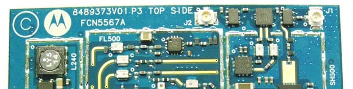
Click to zoom
Application Details
- Equipment Class
- TNB - Licensed Non-Broadcast Station Transmitter
- Date of Grant
- Jun 07, 2006
- Application Purpose
- Original Equipment
- Date of Application
- Jun 07, 2006
- Equipment Note
- 802.11a/b/g WLAN Mini PCI Transmitter Module
- Frequency Range
- 4950.00000000 - 4980.00000000
- Company
- Motorola Solutions, Inc.
- Country
- United States
Documents & Files
Document Text
Text extracted from the exhibit documents filed with the FCC. Open a document above to read the original.
Users Manual
6802978C75-B @6802978C75@ April 2006 User’s Guide WDE1000 CardBus Adaptor WDE1100 Mini PCI Card 6802978C75-B WDE1000 WDE11 00 ii Disclaimer Statements included in this manual indicating support pro- vided by Motorola are subject to changes at any time. Motorola reserves the right to make changes to this manual. Declaration of Conformity If this equipment does cause harmful interference to radio or television reception, which can be determined by turning the equipment off and on, the user is encour- aged to try to correct the interference by one or more of the following measures: •Reorient or relocate the receiving antenna. •Increase the separation between the equipment and receiver. •Connect the equipment into an outlet on a circuit dif- ferent from that to which the receiver is connected. •Consult the dealer or an experienced radio/TV techni- cian for help. As a personal computer peripheral, this device complies with Part 15 of the FCC Rules. Operation is subject to the following two conditions: (1) this device may not cause harmful interference, and (2) this device must accept any interference received, including interference that may cause undesired operation. FCC ID: AZ489FT7016 refers to WDE1000 FCC ID: AZ489FT7023 refers to WDE1100 Per FCC CFR 47 Part 2 Section 2.1077(a) Responsible Party Name: Motorola, Inc. Address: 1301 East Algonquin Road Schaumburg, IL 60196 USA Phone Number: 1-800-221-7144 Hereby declares that the product: Product Name:WDE1000/WDE1100 Model Number: F2889A/F2892A Conforms to the following regulations: FCC Part 15, subpart B, section 15.107(a), 15.107(d) and section 15.109(a) Class B Digital Device This equipment has been tested and found to comply with the limits for a Class B digital device, pursuant to part 15 of the FCC Rules. These limits are designed to provide reasonable protection against harmful interference in a residential installation. This equipment generates, uses and can radiate radio frequency energy and, if not installed and used in accordance with the instructions, may cause harmful interference to radio communications. However, there is no guarantee that interference will not occur in a particular installation. NOTE WDE1100 only. WDE1100 is an OEM module and is intended only for OEM integra- tors under the following condi- tions: 1. The antenna should be installed so there is at least 20cm of separation between the body of the user and nearby persons and the antenna. 2. The OEM Module may not be co-located with any other transmitter or antenna. 3. The antenna installation of this OEM Module, including antenna gain, must satisfy the requirements as specified in FCC ID: AZ489FT7023 grant of equipment authorization. As long as the above conditions are met, further transmitter tests will not be required. However, the OEM integrator is still responsible for testing their end product for any additional compliance requirements required with this Module installed. If the above conditions can not be met then the FCC authorization is no longer considered valid and the FCC ID can not be used on the final product. In this case, the OEM Integrator will be responsible for re- evaluation the end product, including the transmitter, and obtaining a separate FCC authorization. NOTE iii Regulatory Requirements The Federal Communications Commission (FCC) requires application for certification of digital devices in accordance with CFR Title 47, Part 15 and Part 90. This includes Elec- tromagnetic Energy Exposure (EME) testing. As the WDE1000/1100 is not a stand-alone modem but is a PC card, the WDE1000/1100 cannot be tested by itself for EME certification and was tested while inserted in a laptop computer. This device complies with Part 15 of the FCC Rules. Operation is subject to the following two conditions: (1) This device may not cause harmful interference, and (2) This device must accept any interference received, including interference that may cause undesired operation. The WDE1000/1100 transmitters, [email protected] and 802.11b/[email protected] will not work simultaneously when used in the present configuration. Safety and General Information IMPORTANT INFORMATION ON SAFE AND EFFI- CIENT OPERATION. READ THIS INFORMATION BEFORE USING YOUR MOTOROLA WDE1000/1100. RF Operational Characteristics Your Motorola product contains a radio frequency transmit- ter to convey the information you wish to send as well as occasional automatic signals used to sustain connection to the wireless network, and a receiver which enables you to receive communication and connection information from the network. Antenna Care (WDE1000 only) Use only the supplied or an approved replacement antenna. Unauthorized antennas, modifications, or attachments could damage the radio product and may violate FCC regu- lations. When using any approved accessory antenna, posi- tion it at least eight inches (20 cm) from any part of any person. DO NOT hold the antenna when the radio product is "IN USE". Holding the antenna affects communication quality and may cause the product to operate at a higher power level than needed. Compliance and Control Guidelines and Operating Instructions for WDE1100 Installed as Fixed Site If WDE1100 is installed at a fixed location and operated as a fixed unit, the antenna installation must comply with the following requirements in order to ensure optimal perform- ance and compliance with the RF energy exposure limits in the standards and guidelines listed in “Product Operation and EME Exposure” on page iii: •The antenna should be mounted outside the building on the roof or a tower if at all possible. •As with all fixed site antenna installations, it is the responsibility of the licensee to manage the site in accordance with applicable regulatory requirements and may require additional compliance actions such as site survey measurements, signage, and site access restrictions in order to ensure that exposure limits are not exceeded. Product Operation and EME Exposure Your Motoro…
Text truncated - open the document above for the full version.
Attestation Statements
APPLICANT: MOTOROLA, INC. FCC ID: AZ489FT7023 Exhibit 2 Statement of Certification — Pursuant to 47 CFR 2.907 The technical data supplied with this application, having been taken under my supervision is hereby duly certified. The following is a statement of my qualifications: B.Sc in Electrical Engineering, TECHNION, INSTITUTE OF TECHNOLOGY, ISRAEL 10 years experience in RF design and measurement techniques NAME: Tal Bareket SIGNATURE: /s/ Tal Bareket (signed) DATE: May 21, 2006 POSITION: Senior RF Engineer I hereby certify that the above application was prepared under my direction and that to the best of my knowledge and belief, the facts set forth in the application and accompanying technical data are true and correct. NAME: Gadi Shirazi SIGNATURE: /s/ Gadi Shirazi (signed) DATE: May 23, 2006 POSITION: Senior HW Development Manager
Attestation Statements
APPLICANT: MOTOROLA, INC. FCC ID: AZ489FT7023 1 Modular Transmitter Approval Qualification for WDE1100 WDE1100 includes two Transmitters operating at 4.9GHz and 2.4GHz bands. 1. The modular transmitter must have its own RF shielding. This is intended to ensure that the module does not have to rely upon the shielding provided by the device into which it is installed in order for all modular transmitter emissions to comply with Part 15 limits. It is also intended to prevent coupling between the RF circuitry of the module and any wires or circuits in the device into which the module is installed. Such coupling may result in non-compliant operation. R3.1 The transmitters have their own RF shielding. 2. The modular transmitter must have buffered modulation/data inputs (if such inputs are provided) to ensure that the module will comply with Part 15 requirements under conditions of excessive data rates or over-modulation. R3.2 The transmitters have buffered modulation/data inputs. 3. The modular transmitter must have its own power supply regulation. This is intended to ensure that the module will comply with Part 15 requirements regardless of the design of the power supplying circuitry in the device into which the module is installed. R3.3 The transmitters have their own power supply regulation. 4. The modular transmitter must comply with the antenna requirements of Section 15.203 and 15.204(c). The antenna must either be permanently attached or employ a “unique” antenna coupler (at all connections between the module and the antenna, including the cable). Any antenna used with the module must be approved with the module, either at the time of initial authorization or through a Class II permissive change. The “professional installation” provision of Section 15.203 may not be applied to modules. R3.4 The transmitters have a “unique” antenna coupler. Details about the reference 2.4GHz antenna is described in the exhibits. 5. The modular transmitter must be tested in a stand-alone configuration, i.e., the module must not be inside another device during testing. This is intended to demonstrate that the module is capable of complying with Part 15 emission limits regardless of the device into which it is eventually installed. Unless the transmitter module will be battery powered, it must comply with the AC line conducted requirements found in Section 15.207. AC or DC power lines and data input/output lines connected to the module must not contain ferrites, unless they will be marketed with the module (see Section 15.27(a)). The length of these lines shall be length typical of actual use or, if that length is unknown, at least 10 centimeters to insure that there is no coupling between the case of the module and supporting equipment. Any accessories, peripherals, or support equipment connected to the module during testing shall be unmodified or commercially available (see Section 15.31(i)). R3.5 The transmitters have been tested in a stand-alone configuration. APPLICANT: MOTOROLA, INC. FCC ID: AZ489FT7023 2 6. The modular transmitter must be labeled with its own FCC ID number, and, if the FCC ID is not visible when the module is installed inside another device, then the outside of the device into which the module is installed must also display a label referring to the enclosed module. This exterior label can use wording such as the following: “Contains Transmitter Module FCC ID: XYZMODEL1” or “Contains FCC ID: XYZMODEL1.” Any similar wording that expresses the same meaning may be used. The Grantee may either provide such a label, an example of which must be included in the application for equipment authorization, or, must provide adequate instructions along with the module which explain this requirement. In the latter case, a copy of these instructions must be included in the application for equipment authorization. R3.6 The Module is labeled with the FCC ID number, as described in the relevant exhibit. 7. The modular transmitter must comply with any specific rule or operating requirements applicable to the transmitter and the manufacturer must provide adequate instructions along with the module to explain any such requirements. A copy of these instructions must be included in the application for equipment authorization. For example, there are very strict operational and timing requirements that must be met before a transmitter is authorized for operation under Section 15.231. For instance, data transmission is prohibited, except for operation under Section 15.231(e), in which case there are separate field strength level and timing requirements. Compliance with these requirements must be assured. R3.7 No specific rule or operating requirements. 8. The modular transmitter must comply with any applicable RF exposure requirements. For example, FCC Rules in Sections 2.1091, 2.1093 and specific Sections of Part 15, including 15.319(i), 15.407(f), 15.253(f) and 15.255(g), require that Unlicensed PCS, UNII and millimeter wave devices perform routine environmental evaluation for RF Exposure to demonstrate compliance. In addition, spread spectrum transmitters operating under Section 15.247 are required to address RF Exposure compliance in accordance with Section 15.247(b)(4). Modular transmitters approved under other Sections of Part 15, when necessary, may also need to address certain RF Exposure concerns, typically by providing specific installation and operating instructions for users, installers and other interested parties to ensure compliance. R3.8 The Modular Transmitter complies with the applicable RF Exposure requirements, as described in Exhibit 11 (MPE Report).
Cover Letter(s)
8000 West Sunrise Boulevard, Fort Lauderdale, Florida 33322. USA CONFIDENTIALITY REQUEST 25 th May 2006 Authorization & Evaluation Division Federal Communications Commission Laboratory 7435 Oakland Mills Road Columbia, MD 21046 Subject: Confidentiality Request for Transmitter with FCC ID: AZ489FT7023. WDE1100, Model Number: F2892A Dear Sir or Madam: Motorola is requesting that Exhibit 4 (Circuit Descriptions), Exhibit 5 (Schematic Diagrams), Exhibit 10 (Parts List and Tune-Up Procedures), and Exhibit 12 (Operational Description) not be made routinely available for public inspection. Motorola considers the information in these exhibits to be classified as trade secrets, pursuant to 47 CFR Section 0.457(d) and Section 552(b)(4) of the Freedom of Information Act. We are also requesting that the FCC mark Exhibit 3 (External Photos) and Exhibit 9 (Internal Photos) as Temporary Confidentiality as outlined in Public Notice DA 04-1705, dated June 15, 2004. This provision will give Motorola temporary confidentiality prior to product launch. Please mark Exhibits 4, 5, 10, and 12 as “Confidential” And Exhibit 3 and 9 as “Temporary Confidential”. Please contact me if you require any additional information. Sincerely, /s/ Mike Ramnath (signed) Manager, Regulatory Compliance Tel: (954) 723-5793 E-mail: [email protected] EXHIBIT 13b
Cover Letter(s)
FCC ID: AZ489FT7023 25 th May 2006 Authorization & Evaluation Division Federal Communications Commission Laboratory 7435 Oakland Mills Road Columbia, MD 21046 Dear Sir: Motorola Inc., 8000 West Sunrise Boulevard, Fort Lauderdale, Florida 33322, herein submits its application for Certification of the transmitter with FCC ID: AZ489FT7023. This OEM (Original Equipment Manufacturer) WDE1100 is integrated WLAN transceiver module with FCC ID: AZ492FT7023. This WLAN transceiver module will be marketed as an Original Equipment Manufacturer (OEM) module. It shall be embedded in a variety of end products, as described in 47 CFR 2.1091(d) (4). It is supplied neither with battery nor antenna, only with an antenna connector and is classified as a mobile device, as defined in 47 CFR 2.1091(b). Since Motorola neither manufactures nor supplies the antenna(s) that will be used in the final application of this product, it is not possible to measure the MPE of the actual device as it will be integrated into the end product. Therefore MPE calculation was done with the MPE General Population limits for a mobile device in Table 1(B) of 47 CFR 1.1310 as required by 47CFR 2.1091(c). The subject transmitter complies with CFR 47 part 90 and CFR 47 part 15.247. Contact me at (954) 723-5793 if you require any additional information. Sincerely, /s/ Mike Ramnath (signed) Manager, Regulatory Compliance Email: [email protected]
ID Label/Location Info
APPLICANT: MOTOROLA, INC. FCC ID: AZ489FT7023 Exhibit 1 FCC Identification Label - Pursuant to 47 CFR 2.925, 2.1033(b) 7 and 2.1033(c) 11 1.1 FCC ID: AZ489FT7023 Identifier label for model: F2892A Photograph 1.1: Identifier Label photo. 1.2 Label Location: Label is located on top side of the Mini-PCI Card. Photograph 1.2: Label Location photo. APPLICANT: MOTOROLA, INC. FCC ID: AZ489FT7023 Exhibit 1 1.3 Type: Identifier Label: The label is a white paper with a pressure sensitive adhesive backing. The adhesive is a permanent type acrylic with minimum peel strength of 2 lbs/in. Total thickness paper and adhesive is 0.10 mm. "Hot Surface" Label: The label material is polyester 0.08 mm thick with a pressure sensitive adhesive backing. The adhesive is a permanent type acrylic with minimum peel strength of 2 lbs/in. Total thickness polyester and adhesive is 0.13 mm. Exhibit 1A: General Information 1A.1. Production Plans Quantity production is planned. 1A.2. Application References -- Pursuant to 47 CFR 2.948 Reference is made to the following Motorola "Application References" HERMON LABORATORIES, located in Binyamina Israel is listed with FCC as follows: 1. FCC OATS – registered name "HERMON LABORATORIES" .Our registration number is: 90624. 2. FCC Anechoic chamber registration number is: 90623 3. Accredited by A2LA. 1A.3. Data Submittal Procedure Data located in Exhibit 6 is supplied in accordance with the following: For license section: Part 90, Subparts I and Y, Part 2, Subpart J, Part 15, Subpart B, Section 15.109 For un- license section: Part 15, Subparts B and C. All Subparts are of the Commission’s rules in CFR 47. 1A.4. Similar, currently Certified transmitter N/A.
Internal Photos
APPLICANT: MOTOROLA, INC. FCC ID: AZ489FT7023 Exhibit 9 Internal Photographs Photograph 9.1: Top view of WDE1000. Photograph 9.2: Top view of WDE1000. APPLICANT: MOTOROLA, INC. FCC ID: AZ489FT7023 Exhibit 9 Photograph 9.3: Bottom view of WDE1000.
RF Exposure Info
FCC ID: AZ489FT7023 SR4102 Page 1 of 4 Certificate Number: 1449-01 FCC ID: AZ489FT7023 DECLARATION OF COMPLIANCE MPE ASSESSMENT Network & Enterprise Mobility Solutions EME Test Laboratory 8000 West Sunrise Blvd Fort Lauderdale, FL. 33322 Date of Report: May 24, 2006 Report Revision: Rev. A Report ID: FCC MPE rpt_WDE1100_Rev A_060524 SR4102 Responsible Engineer: Kim Uong (EME Engineer) Date/s Tested: N/A (MPE-Numerical assessment) Manufacturer/Location: Motorola, Israel Date submitted for test: 5/18/06 DUT Description: WDE1100 - Wireless Device Enabler 4.9GHz (802.11a); 2.4GHz (802.11b/g) Test TX mode(s): N/A (MPE-Numerical assessment) Max. Power output: 0.126W for 4.9GHz, 0.071W for 2.4GHz TX Frequency Bands: 4942.5 – 4987.5 MHz and 2412 - 2462 MHz Signaling type: OFDM @ 4.9GHz; DSSS and OFDM @ 2.4GHz. Model(s) Tested: N/A (MPE-Numerical assessment) Model(s) Certified: F2892A Serial Number(s): NA Classification: General Population/Uncontrolled Rule Part(s): 90 Based on the information provided herein, the undersigned certifies that when used as stated in the operating instructions supplied, said product complies with the FCC standard 47 CFR §1.1310. This report shall not be reproduced without written approval from an officially designated representative of the Motorola EME Laboratory. Signature on file - Stephen Whalen for Ken Enger Ken Enger GEMS EME Lab Senior Resource Manager, Laboratory Director, Approval Date: 5/24/06 Certification Date: 5/24/06 Certification No.: L1060538 FCC ID: AZ489FT7023 SR4102 Page 2 of 4 TABLE OF CONTENTS 1.0 Product and System Description 2.0 Evaluation methods 3.0 MPE Analysis 4.0 Conclusion REVISION HISTORY Date Revision Comments 5/8/06 O Original release 5/24/06 A Revise max power for 2412 – 2462MHz frequency band. FCC ID: AZ489FT7023 SR4102 Page 3 of 4 1.0 Product and System Description The WDE1100 model F2892A FCC ID AZ489FT7023 is an OEM module that is capable of operating in the 4942.5-4987.5MHz (802.11a); and 2412-2462MHz bands (802.11b/g). The rated conducted power is 0.1 Watt for 4942.5-4987.5MHz; 0.063W for 2412- 2462MHz. The maximum conducted output power is 0.126 Watts and 0.071 Watts respectively as defined by the upper limit of the production line final test station. The transmitters listed above, 802.11a and 802.11b/g, will not transmit simultaneously. Motorola neither manufactures nor supplies the antenna(s) and host housing(s) that will be used in future systems integrations. The User manual for this product instructs the Systems Integrator to assure that transmission occurs only when the operator and nearby persons are at least 20 cm from the antenna. Therefore, this product will be evaluated as a mobile device per 47 CFR §1.1310 titled “Radio frequency radiation exposure limits”, generally referred to as Maximum Permissible Exposure (MPE) limits, for General Population. 2.0 Evaluation methods: MPE numerical assessment is used to evaluate the RF exposure of this WDE1100 OEM module based on a maximum antenna gain of 6dBi for 2412 – 2462MHz band and 9dBi for 4942.5 – 4987.5MHz band. According to OET Bulletin 65 Edition 97-01 Section 2, calculations can be made to predict RF field strength and power density levels around typical RF sources. For example, in the case of a single radiating antenna, a prediction for power density in the far-field of the antenna can be made by use of the general Equations (3) or (4) below. These equations are generally accurate in the far-field of an antenna but will over-predict power density in the near field, where they could be used for making a "worst case" or conservative prediction. 2 4R PG S π = (3) Where: S = power density (mW/cm^2) P = power input to the antenna (mW) G = power gain of the antenna in the direction of interest relative to an isotropic radiator R = distance to the center of radiation of the antenna (cm) Or 2 4R EIRP S π = (4) Where: EIRP = equivalent (or effective) isotropically radiated power FCC ID: AZ489FT7023 SR4102 Page 4 of 4 3.0 MPE Analysis: Specification Limit - FCC Max Permissible Exposure (mW/cm2) Max Antenna Gain Max power (W) Frequency Range (MHz) Distance (cm) Radiated power density (mW/cm2 ) (*)Radiated power density for a perfect reflecting ground plane (mW/cm2) Uncontrolled Controlled 6 dBi 0.071 2412 - 2462 20 0.06 0.22 1 5 9 dBi 0.126 4942.5 - 4987.5 20 0.20 0.80 1 5 Note: (*) A perfect reflecting ground plane, in-phase field combination is assumed, resulting in a four-fold power density increase. 4.0 Conclusion: The MPE results for WDE1100 per the assessment above are compliant to the FCC General population/Uncontrolled exposure limits of 1 mW/cm 2 for the frequency ranges above 1500MHz per 47 CFR §1.1310 titled “Radio frequency radiation exposure limits”.
Test Report
APPLICANT: MOTOROLA, INC. FCC ID: AZ489FT7023 Page 1 of 119 Exhibit 6 Exhibit 6: Measured Data Report Measurement Test Report On the Motorola 802.11a @ 4.9GHz and 802.11b/g WDE1100 MINI-PCI Card Model: F2892A FCC ID: AZ489FT7023 In Accordance With: FCC CFR 47 Part 90 FCC CFR 47 Part 15.247 APPLICANT: MOTOROLA, INC. FCC ID: AZ489FT7023 Page 2 of 119 Exhibit 6 6.1 Tests required: Section Test Standard Description Pass / Fail Tests required for 802.11a @ 4.9GHz 6.2 EUT Description & Test Configuration for 802.11a @ 4.9GHz 6.3 §90.1215 (a) Peak Transmit Power Pass 6.4 §90.1215 (a) Peak Power Spectral Density Pass 6.5 §90.210 (m) Occupied Bandwidth: Emission Mask M Pass 6.6 §90.210 (m) Spurious Emissions at Antenna Terminal Pass 6.7 §90.210 (m) Radiated spurious Emissions Pass 6.8 §2.1055 (a)(1); §90.213 Frequency Stability, Temperature Variations Pass 6.9 §2.1055 (d)(1); §90.213 Frequency Stability; Voltage Variations Pass 6.10 §15.109(a) Radiated Emission Pass 6.11 §15.107(a); §15.207(a) Conducted Emissions on AC power line Pass Tests required for 802.11b/g 6.12 EUT Description & Test Configuration for 802.11b/g 6.13 §15.247(b)(3) Peak output power Pass 6.14 §15.247(a)(2) 6dB Bandwidth Pass 6.15 §15.247(d) Peak Power Spectral Density Pass 6.16 §15.247(c) Conducted Spurious Emissions Pass 6.17 §15.247(c) Radiated Spurious Emissions Pass 6.18 §15.109(a) Radiated Emission Pass 6.19 §15.107(a); §15.207(a) Conducted Emission at AC power line Pass APPLICANT: MOTOROLA, INC. FCC ID: AZ489FT7023 Page 3 of 119 Exhibit 6 6.2 EUT Description & Test Configuration for 802.11a @ 4.9GHz: 6.2.1 Equipment used as local support for testing: Table 6.2.1: EUT Support Equipment. No Remote support equipment was used during tests. 6.2.2 I/O port configuration during testing: Table 6.2.2: EUT I/O Ports. Port Type Port Description Connected From/to Connector Type QuantityCable Type Cable Length RF in/out 4.9GHz External Antenna EUT External Antenna UFL 1 Termination N/A RF in/out 2.4GHz External Antenna Not Used in Part 90 Tests UFL 1 N/A N/A 6.2.3 EUT operating mode During Tests: EUT was transmitting at duty cycle of 99% at the Bandwidth stated in each test. The Rate used for each Bandwidth was the highest rate. For Frequency stability the EUT was placed into a CW mode. Description Manufacturer Model Serial Number Notes Laptop HP Compaq nc8230 CNU5111RTB Laptop Motorola ML900 343CEN0366 Used for Frequency Stability tests only APPLICANT: MOTOROLA, INC. FCC ID: AZ489FT7023 Page 4 of 119 Exhibit 6 6.2.4 802.11a @ 4.9GHz Transmitter description Type of equipment Stand-alone (Equipment with or without its own control provisions) Combined equipment (Equipment where the radio part is fully integrated within another type of equipment) V Plug-in card (Equipment intended for a variety of host systems) Intended use Condition of use V fixed Always at a distance more than 2 m from all people V mobile Always at a distance more than 20 cm from all people portable May operate at a distance closer than 20 cm to human body Equipment code TNB Assigned frequency range 4940 – 4990 MHz Operating frequency range 4950 – 4980 MHz for 20MHz BW 4945 – 4985 MHz for 10MHz BW 4942.5 – 4987.5 MHz for 5MHz BW RF channel spacing 20, 10, 5 MHz At transmitter 50 Ω RF output connector 126mW Maximum rated output power Effective radiated power (for equipment with no RF connector) N/A No Continuous variable V Stepped variable with step size 41% Minimum RF power 50.1mW Is transmitter output power variable? V Yes Nominal RF power 100mW Antenna connection With temporary RF connector Unique coupling V Standard connector V Integral V Without temporary RF connector Antenna/s technical characteristics Type Manufacturer Model number Gain N/A N/A N/A N/A Transmitter 99% power bandwidth 16.5MHz(20MHz), 8.25MHz(10MHz), 4.125MHz(5MHz) Transmitter aggregate data rate/s (Data rates According to 802.11a sec 17.3.2.2) 6, 9, 12, 18, 24, 36, 48, 54 Mbps for 20MHz BW 3, 4.5, 6, 9, 12, 18, 24, 27 Mbps for 10MHz BW 1.5, 2.25, 3, 4.5, 6, 9, 12, 13.5 Mbps for 5MHz BW Transmitter aggregate symbol (baud) rate/s (According to 802.11a sec 17.3.2.2) 6, 9, 6, 9, 6, 9, 8, 9 Msps respectively to data rate at 20MHz BW 3, 4.5, 3, 4.5, 3, 4.5, 4, 4.5 Msps respectively to data rate at 10MHz BW 1.5, 2.25, 1.5, 2.25, 1.5, 2.25, 2, 2.25 Msps respectively to data rate at 5MHz BW Type of modulation 48 subcarriers modulated with BPSK,/QPSK /16-QAM/ 64-QAM + 4 pilot sub carriers modulated with BPSK Type of multiplexing TDD OFDM Modulating test signal (base band) PN9 Maximum transmitter duty cycle in normal use 1.5Mbps @ 5MHz 13.5Mbps @ 5MHz 3Mbps @ 10MHz 27Mbps @ 10MHz 6Mbps @ 20MHz 54Mbps @ 20MHz 60% Tx ON time 21.936mSec 2.512mSec 10.968mSec 1.256mSec 5.484mSec 628uSec Period 36.56mSec 4.186mSec 18.28mSec 2.093mSec 9.14mSec 1.046mSec Transmitter duty cycle supplied for test 1.5Mbps @ 5MHz 13.5Mbps @ 5MHz 3Mbps @ 10MHz 27Mbps @ 10MHz 6Mbps @ 20MHz 54Mbps @ 20MHz 99% Tx ON time 12.42mSec 1.472mSec 6.217mSec 736uSec 3.1mSec 368uSec Period 12.55mSec 1.492mSec 6.28mSec 746uSec 3.14mSec 373uSec Transmitter power source Battery Nominal rated voltage ..........VDC Battery type Ni- Cd, Lithium, Lead- Acid, other V DC Nominal rated voltage 3.3 VDC ± 10% AC mains Nominal rated voltage ..........VAC Frequency ..........Hz Is there common power source for transmitter and receiver V yes no Emission designator 20M0X1D, 10M0X1D, 5M00X1D APPLICANT: MOTOROLA, INC. FCC ID: AZ489FT7023 Page 5 of 119 Exhibit 6 6.3 Peak Transmit Power - Pursuant to 47 CFR §90.1215 (a) 6.3.1 Test Procedure: • A laptop was connected to the EUT to control the RF output power and Frequency. • The EUT 4.9GHz RF Output Connector was connected through Calibrated Attenuators to a Power Meter with a sensor capable of measuring the entire bandwidth of the signal. • The EUT power was adjusted at the maximum and the minimum output power level. • Procedure was repeated for the 5MHz, 10MHz and 20MHz bandwidths at lower, mid and upper channels a…
Text truncated - open the document above for the full version.
Test Report
FCC ID: AZ489FT7023 Date: 7 th June 2006 Gregory Czumak PCTEST Engineering Laboratory, Inc. 6660-B Dobbin Road Columbia, MD 21045 Re: Correspondence Number: AZ40280 with FCC ID: AZ489FT7023. Confirmation Number: 1605250280 Dear Mr. Czumak; Motorola Inc., 8000 West Sunrise Boulevard, Fort Lauderdale, Florida 33322, herein submits its response to the 6 th June 2006 request for information in Correspondence Number: AZ40280. Q1. The statement required by Section 15.21 is not in the User’s Manual. Please verify that it will be included in the Manual prior to shipment of the EUT. R1. We are confirming that the said language in Rule Part 15.21 will be added to the Users Manual prior to shipment of the WDE1100. Q2. Please describe the “external reference antenna” used for spurious radiated emission tests of the Part 15C transmitter (please note that this Rule Section is now 15.247(d)). What is its gain? R2. Peak Gain of the external reference antenna of the part 15C is 2.56dBi. Please be informed that Ex 6 page no. 50, Section Antenna's technical characteristics was revised. This information was mistakenly copied from Exhibit 6 of the WDE1000 documentation. Ex6 is now amended with the correct information. Q3. Please address the Modular Approval requirements (see the attached document) specified by the FCC for the Part 15C transmitter (only those points that are applicable to the EUT- the remainder are covered by the Grant and usage conditions, hence, the EUT is a LIMITED Modular Approval). R3. According to the attached document, Limited Modular approval will be applicable if compliance to one of the items cannot be met. Since we meet all requests in this DA 00-1407, we believe a Modular full Modular approval is warranted. Contact me at (954) 723-5793 if you require any additional information. Sincerely, /s/ Mike Ramnath (signed) Manager, Regulatory Compliance Email: [email protected]
Test Setup Photos
APPLICANT: MOTOROLA, INC. FCC ID: AZ489FT7023 Exhibit 7 Measurement setup photos Photograph 7.1: Output Power Mea…
Text truncated - open the document above for the full version.
Contact Information
Applicant
Arine Lee(Certification Manager)
Technical Contact
PCTEST Engineering Laboratory, Inc.Randy Ortanez
[email protected]410-290-6652
6660-B Dobbin Road · Columbia, Maryland · United States
Test Firm
MotorolaWilliam Elliott
Technical Specifications
| # | Rule Parts | Frequency Range | Power Output | Emission | Tolerance |
|---|---|---|---|---|---|
| 3 | 9 | 4.95 GHz - 4.98 GHz | 126.00 mW | 20M0X1D | 1 ppm |
Other Applications from Motorola Solutions, Inc.

AZ489FT4980
Sep 08, 2026Portable two way radio
Equipment Class
TNF - Licensed Non-Broadcast Transmitter Held to FaceAZ489FT4981
Aug 14, 2026Handheld Portable - TANAPA BPR 45 400-470 MHZ 4W NKP
Equipment Class
TNF - Licensed Non-Broadcast Transmitter Held to Face
AZ489FT7187
Jul 13, 2026Portable 2-Way Radio with Bluetooth, Bluetooth LE, WIFI 2.4GHz, WIFI 5GHz, LTE
Equipment Class
DSS - Part 15 Spread Spectrum TransmitterAZ499FT6031
May 11, 2026Operation Critical Wireless Earpiece PTT
Equipment Class
DSS - Part 15 Spread Spectrum Transmitter
AZ499FT5879
Dec 19, 20252-way Portable Radio with BT, BTLE, WIFI, NFC and LTE
Equipment Class
DSS - Part 15 Spread Spectrum Transmitter