AZ489FT7024Bluetooth Phone Module
Motorola Solutions, Inc.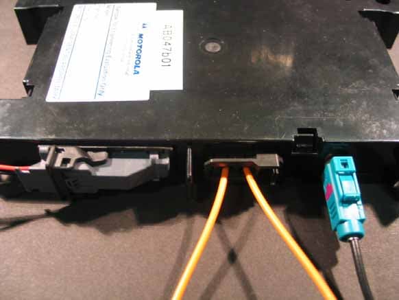
Click to zoom
Application Details
- Equipment Class
- DSS - Part 15 Spread Spectrum Transmitter
- Date of Grant
- Jan 25, 2006
- Application Purpose
- Original Equipment
- Date of Application
- Jan 25, 2006
- Equipment Note
- Bluetooth Phone Module
- Frequency Range
- 2402.00000000 - 2480.00000000
- Company
- Motorola Solutions, Inc.
- Country
- United States
Documents & Files
Document Text
Text extracted from the exhibit documents filed with the FCC. Open a document above to read the original.
Users Manual
IVlOTOROLA To whom it may concern January 25th 20oo We, Motorola Automotive, Jays Close, Viables Industrial Estate, Basingstoke, Hampshire, RG22 4PD, UK, hereby declare, that the product Motorola BPM (Bluetooth Phone Module) model Pxx BPM Wilf have the FCC statement warning appended to the end user manual. Statement 15.21: lnformation to user changes or modifications note expressly approved by the patty responsrble for compliance could avoid the usefs authority to operate the equipment. The end user manual is the responsibility of the vehicle manufacturer and we confirm from them that they will add the statement at the next update/release of their manual. Yours sincerely MOTOROLA r I ,l It ii i il t I -1"i"'ttbfil*-*.-; Harold Innes Programme Manager January 25tn, 2006
External Photos
BPM - Top View BPM – Bottom View
ID Label/Location Info
BPM - Top View
Operational Description
Product Description Document Version: Draft 3 PAG BPM Date: 14-July -05 Page: 1 (16) Product Description Document (PDD): PAG BPM Version: Draft 3 Date: 14-July-2005 Abstract: This document defines the functional baseline for the PAG BPM release including the system and subsystem architectures, itemized feature list, and high-level feature descriptions. File Name: PAG_BPM_PDD Draft 3.doc Motorola Internal Use Only Product Description Document Version: Draft 3 PAG BPM Date: 14-July -05 Page: 2 (16) Revision History: Date dd-mm-yyy Revision Revision Author Comments 04-04-2003 Draft D. McCartney Initial Draft 09-04-2003 Draft 1 D. McCartney Updated to include DTMF Send, VDA 1.1, Redial, Speed Dial, SMS Send, SMS Management details, HELP Display at HMI. 29-04-2003 Draft 2 D. McCartney Update to include : Last Number/Redial List Sync, Auto Answer, Audio Parameter Settings, Locking MO Calls, Call Hold, DTMF via VR, MT Call Announcer and dial from NAV in support of the TA Baseline 14-07-2005 Draft 3 D. McCartney Update to align with the many changes in both Hardware and functional aspects. File Name: PAG_BPM_PDD Draft 3.doc Motorola Internal Use Only Product Description Document Version: Draft 3 PAG BPM Date: 14-July -05 Page: 3 (16) Table of Contents: 1. PURPOSE.................................................................................................................5 2. OVERVIEW...............................................................................................................5 2.1 SYSTEM ARCHITECTURE...................................................................................................................6 2.2 PAG BPM SUB-SYSTEM ARCHITECTURE..........................................................................................7 3. FEATURE MATRIX..................................................................................................8 4. SYSTEM FEATURE DESCRIPTION......................................................................11 4.1 BLUETOOTH PROFILES...................................................................................................................11 4.1.1 Core.......................................................................................................................................11 4.1.2 Hands Free Profile (HFP).......................................................................................................11 4.1.3 Headset Profile (HSP)............................................................................................................11 4.1.4 Phone Access Profile (PAP)...................................................................................................11 4.1.5 Object Exchange (OBEX).......................................................................................................11 4.2 OPERATIONS AND MAINTENANCE.....................................................................................................11 4.2.1 BPM Self Diagnostics............................................................................................................11 4.2.2 BPM End of Line Configuration Parameter Management.....................................................11 4.2.3 BPM Service/Dealer Diagnostics..........................................................................................11 4.2.4 BPM Reflash.........................................................................................................................12 4.3 HANDSFREE.................................................................................................................................. 12 4.3.1 BPM Noise Suppression and Echo Cancellation...................................................................12 4.4 HMI.............................................................................................................................................12 4.4.1 BPM Status Reporting............................................................................................................12 4.4.2 Command Interface................................................................................................................12 4.4.3 Help........................................................................................................................................12 4.5 PERSONAL CALLING.......................................................................................................................12 4.5.1 Bluetooth Device Status.........................................................................................................12 4.5.2 Mobile Originating/Terminating..............................................................................................12 4.5.3 Call Waiting............................................................................................................................12 4.5.4 Calling Line ID (CLI)...............................................................................................................13 4.5.5 Privacy/Handsfree Selection..................................................................................................13 4.5.6 DTMF Send............................................................................................................................13 4.6 PHONEBOOK................................................................................................................................. 13 4.6.1 Calling and Scrolling..............................................................................................................13 4.7 POWER MANAGEMENT...................................................................................................................13 4.7.1 Wake-up................................................................................................................................. 13 4.7.2 Delayed Power Down............................................................................................................…
Text truncated - open the document above for the full version.
Operational Description
1 Project: 4_MOT_0505_TAS Bluetooth Phone Module BPM Product information summary 1. Basic product information Brand name Motorola Inc. Type designation BPM Frequency range 2402 MHz-2480 MHz Modulation FHSS Transmitter power 5, 79 dBm. the EIRP including internal antenna gain(1,5dBi) is 7,29 dBm Duty cycle 0,377 Power supply 12V DC External antenna Optional Standard(s) Applied EN 301 489-1 08/2002 ETSI EN 300 328-2 V1.6.1(2004-11) EN: 60950-1:2001 FCC Part 15, Subpart C, §15.247 2. Product Functionality description The Motorola BPM will provide consumers with the ability to make and receive hands-free personal calls within their vehicles by interacting with the BPM through Voice Recognition (VR) and invehicle HMI. The BPM uses the capabilities within the consumer’s personal Portable Phone connected via Bluetooth to access the cellular network. Key features include speaker independent continuous digit dialling, voice tag dialling and high quality handsfree audio processing. Additionally, the BPM provides run-time and on- demand diagnostics capabilities and provides configurable parameter management and software update capabilities. 2 3. System Architecture Please note customer’s external cellular phone is out of scope of this application. 4. Reference 4.1. Product Description Document (PDD). Filename “Operation_Description_(PDD).pdf”. 4.2. Block diagram. Filename “PAG BPM Functional Block Diagram.pdf”.
Test Report
Registergerichth registered in:Vorstandh Board of Directors:7 layers AG, Borsigstrasse 11 Ratingen HRB 3264Dr. Wolfgang Dahm40880 Ratingen, Germany AufsichtsratsvorsitzendehDr. Hans-Jürgen MeckelburgPhone: +49 (0) 2102 749 0 Chairman of the Supervisory Board:Fax: +49 (0) 2102 749 350 Dr. Sabine Grobeckerwww.7layers.com Annex Additional declaration part according FCC 15.247 for Bluetooth TM Devices Version: 2002-06-01 Annex - Additional declaration part according FCC 15.247 for Bluetooth devices Page 2 of 5 pages 1 Output power and channel separation of a Bluetooth device in the different operating modes: The different operating modes (data-mode, acquisition-mode) of a Bluetooth device don’t influence the output power and the channel spacing. There is only one transmitter which is driven by identical input parameters concerning these two parameters. Only a different hopping sequence will be used. For this reason the check of these RF parameters in one op-mode is sufficient. 2 Frequency range of a Bluetooth device: Hereby we declare that the maximum frequency of this device is: 2402 – 2480 MHz. This is according the Bluetooth Core Specification (+ critical errata) for devices which will be operated in the USA. This was checked during the Bluetooth Qualification tests (Test Case: TRM/CA/04-E). Other frequency ranges ( e.g. for Spain, France, Japan) which are allowed according the Core Specification are not supported by this device. 3 Co-ordination of the hopping sequence in data mode to avoid simultaneous occupancy by multiple transmitters: Bluetooth units which want to communicate with other units must be organised in a structure called piconet. This piconet consist of max. 8 Bluetooth units. One unit is the master the other seven are the slaves. The master co-ordinates frequency occupation in this piconet for all units. As the master hop sequence is derived from its BD address which is unique for each Bluetooth device, additional masters intending to establish new piconets will always use different hop sequences. 4 Example of a hopping sequence in data mode: Example of a 79 hopping sequence in data mode: 40, 21, 44, 23, 42, 53, 46, 55, 48, 33, 52, 35, 50, 65, 54, 67, 56, 37, 60, 39, 58, 69, 62, 71, 64, 25, 68, 27, 66, 57, 70, 59, 72, 29, 76, 31, 74, 61, 78, 63, 01, 41, 05, 43, 03, 73, 07, 75, 09, 45, 13, 47, 11, 77, 15, 00, 64, 49, 66, 53, 68, 02, 70, 06, 01, 51, 03, 55, 05, 04 Annex - Additional declaration part according FCC 15.247 for Bluetooth devices Page 3 of 5 pages 5 Equally average use of frequencies in data mode and behaviour for short transmissions: The generation of the hopping sequence in connection mode depends essentially on two input values: 1. LAP/UAP of the master of the connection 2. Internal master clock The LAP (lower address part) are the 24 LSB’s of the 48 BD_ADDRESS. The BD_ADDRESS is an unambiguous number of every Bluetooth unit. The UAP (upper address part) are the 24 MSB’s of the 48 BD_ADDRESS. The internal clock of a Bluetooth unit is derived from a free running clock which is never adjusted and is never turned off. For synchronisation with other units only offset are used. It has no relation to the time of the day. Its resolution is at least half the RX/TX slot length of 312.5 μs. The clock has a cycle of about one day (23h30). In most case it is implemented as 28 bit counter. For the deriving of the hopping sequence the entire LAP (24 bits), 4 LSB’s (4 bits) (Input 1) and the 27 MSB’s of the clock (Input 2) are used. With this input values different mathematical procedures (permutations, additions, XOR- operations) are performed to generate the sequence. This will be done at the beginning of every new transmission. Regarding short transmissions the Bluetooth system has the following behaviour: The first connection between the two devices is established, a hopping sequence was generated. For transmitting the wanted data the complete hopping sequence was not used. The connection ended. The second connection will be established. A new hopping sequence is generated. Due to the fact that the Bluetooth clock has a different value, because the period between the two transmission is longer (and it cannot be shorter) than the minimum resolution of the clock (312.5 μs). The hopping sequence will always differ from the first one. 6 Receiver input bandwidth and behaviour for repeated single or multiple packets: The input bandwidth of the receiver is 1 MHz. In every connection one Bluetooth device is the master and the other one is the slave. The master determines the hopping sequence (see chapter 5). The slave follows this sequence. Both devices shift between RX and TX time slot according to the clock of the master. Additionally the type of connection (e.g. single or multislot packet) is set up at the beginning of the connection. The master adapts its hopping frequency and its TX/RX timing according to the packet type of the connection. Also the slave of the connection will use these settings. Repeating of a packet has no influence on the hopping sequence. The hopping sequence generated by the master of the connection will be followed in any case. That means, a repeated packet will not be send on the same frequency, it is send on the next frequency of the hopping sequence. Annex - Additional declaration part according FCC 15.247 for Bluetooth devices Page 4 of 5 pages 7 Dwell time in data mode The dwell time of 0.3797s within a 30 second period in data mode is independent from the packet type (packet length). The calculation for a 30 second period is a follows: Dwell time = time slot length * hop rate / number of hopping channels *30s Example for a DH1 packet (with a maximum length of one time slot) Dwell time = 625 μs * 1600 1/s / 79 * 30s = 0.3797s (in a 30s period) For multislot packet the hopping is reduced according to the length of the packet. Example for a DH5 packet (with a maximum length of five time slots) Dwell time = 5 * 625 μs * 1600 * 1/5 *1/s / 79 * 30s = …
Text truncated - open the document above for the full version.
Test Report
7 layers AG Aufsichtsratsvorsitzenderh Registergerichth registered in: Borsigstrasse 11 Chairman of the Supervisory Board: Düsseldorf, HRB 44096 40880 Ratingen, Germany Markus Becker USt-IdNr h VAT Nr: Phone: +49 (0) 2102 749 0 Vorstandh Board: DE 203159652 Fax: +49 (0) 2102 749 350 Dr. Hans-Jürgen Meckelburg www.7Layers.com René Schildknecht InterLab is a registered trademark of 7 layers AG FCC Measurement/Technical Report on Bluetooth ® transceiver, car phone module BPM Report Reference: 4_MOT_0505_TAS_FCCb Test Laboratory: 7 layers AG Borsigstrasse 11 40880 Ratingen Germany email: [email protected] DAT-P-192/99-01 Note: The following test results relate only to the devices specified in this document. This report shall not be reproduced in parts without the written approval of the testing laboratory. Testreport Reference: 4_MOT_0505_TAS_FCCb Page 2 of 49 Table of Contents 0 Summary 3 0.1 Technical Report Summary 3 0.2 Measurement Summary 4 1 Administrative Data 6 1.1 Testing Laboratory 6 1.2 Project Data 6 1.3 Applicant Data 6 1.4 Manufacturer Data 6 2 Product labeling 7 2.1 FCC ID label 7 2.2 Location of the label on the EUT 7 3 Test object Data 8 3.1 General EUT Description 8 3.2 EUT Main components 9 3.3 Ancillary Equipment 9 3.4 EUT Setups 9 3.5 Operating Modes 9 4 Test Results 10 4.1 Occupied bandwidth 10 4.2 Peak power output 12 4.3 Spurious RF conducted emissions 14 4.4 Spurious radiated emissions 16 4.5 Band edge compliance 20 4.6 Dwell time 22 4.7 Channel separation 24 4.8 Number of hopping frequencies 25 5 Test Equipment 26 6 Photo Report 29 7 Setup Drawings 31 8 Annex measurement plots 32 8.1 Occupied bandwidth 32 8.2 Peak power output 35 8.3 Band edge compliance conducted and Spurious RF conducted emission38 8.4 Dwell time 45 8.5 Channel separation 48 8.6 Number of hopping frequencies 49 Testreport Reference: 4_MOT_0505_TAS_FCCb Page 3 of 49 0 Summary 0.1 Technical Report Summary Type of Authorization Certification for an Intentional Radiator (Frequency Hopping Spread Spectrum). Applicable FCC Rules Prepared in accordance with the requirements of FCC Rules and Regulations as listed in 47 CFR Ch.1 Parts 2 (10-1-04 Edition) and 15 (10-1-04 Edition). The following subparts are applicable to the results in this test report. Part 2, Subpart J - Equipment Authorization Procedures, Certification Part 15, Subpart C – Intentional Radiators § 15.201 Equipment authorization requirement § 15.207 Conducted limits § 15.209 Radiated emission limits; general requirements § 15.247 Operation within the bands 902-928 MHz, 2400-2483.5 MHz and 5725-5850 MHz Note: The tests were selected and performed with reference to the FCC Public Notice DA 00- 705, released March 30, 2000 Instead of applying ANSI C63.4-1992 which is referenced in the FCC Public Note, the newer ANSI C63.4-2003 is applied. Summary Test Results: The EUT complied with all performed tests as listed in chapter 0.2 Measurement Summary. Testreport Reference: 4_MOT_0505_TAS_FCCb Page 4 of 49 0.2 Measurement Summary FCC Part 15, Subpart C § 15.247 (a) (1) Occupied bandwidth The measurement was performed according to FCC § 15.31 2004 OP-Mode Setup Port Final Result op-mode 1 Setup_b01 Temp.ant.connector passed op-mode 2 Setup_b01 Temp.ant.connector passed op-mode 3 Setup_b01 Temp.ant.connector passed FCC Part 15, Subpart C § 15.247 (b) (1) Peak power output The measurement was performed according to FCC § 15.31 2004 OP-Mode Setup Port Final Result op-mode 1 Setup_b01 Temp.ant.connector passed op-mode 2 Setup_b01 Temp.ant.connector passed op-mode 3 Setup_b01 Temp.ant.connector passed FCC Part 15, Subpart C § 15.247 (d) Spurious RF conducted emissions The measurement was performed according to FCC § 15.31 2004 OP-Mode Setup Port Final Result op-mode 1 Setup_b01 Temp.ant.connector passed op-mode 2 Setup_b01 Temp.ant.connector passed op-mode 3 Setup_b01 Temp.ant.connector passed FCC Part 15, Subpart C § 15.247 (d), § 15.35 (b), § 15.209 Spurious radiated emissions The measurement was performed according to ANSI C63.4 2003 OP-Mode Setup Port Final Result op-mode 1 Setup_a01 Enclosure passed op-mode 2 Setup_a01 Enclosure passed op-mode 3 Setup_a01 Enclosure passed FCC Part 15, Subpart C § 15.247 (d) Band edge compliance The measurement was performed according to FCC § 15.31 (2004) / ANSI C63.4 (2003) 2004 / 2003 OP-Mode Setup Port Final Result op-mode 1 Setup_b01 Temp.ant.connector passed op-mode 3 Setup_b01 Temp.ant.connector passed op-mode 3 Setup_a01 Enclosure passed Testreport Reference: 4_MOT_0505_TAS_FCCb Page 6 of 49 1 Administrative Data 1.1 Testing Laboratory Company Name: 7 Layers AG Address Borsigstr. 11 40880 Ratingen Germany This facility has been fully described in a report submitted to the FCC and accepted under the registration number 96716 . The test facility is also accredited by the following accreditation organisation: - Deutscher Akkreditierungs Rat DAR-Registration no. DAT-P-192/99-01 Responsible for Accreditation Scope: Dipl.-Ing. Bernhard Retka Dipl.-Ing. Arndt Stöcker Dipl.-Ing. Thomas Hoell Report Template Version: 2005-04-26 1.2 Project Data Responsible for testing and report: Dipl.-Ing. Robert Machulec Date of Test(s): 2005-09-27 to 2005-11-03 Date of Report: 2006-01-16 1.3 Applicant Data Company Name: Motorola Automotive, Government, Enterprise and Mobility Solutions Jays Close Address: Basingstoke, Hampshire RG22 4PD UK Contact Person: Harold Innes Tel: +44 (0)1256 488056 Fax: +44 (0)1256 477600 Portable: +44 (0)7860 840504 Email: [email protected] 1.4 Manufacturer Data Company Name: please see applicant data Address: Contact Person: Testreport Reference: 4_MOT_0505_TAS_FCCb Page 7 of 49 2 Product labeling 2.1 FCC ID label At the time of the report there was no FCC label available. 2.2 Location of the label on the EUT see above Testreport Reference: 4_MOT_0505_TAS_FCCb Page 8 of 49 3 Test object Data 3.1 General EUT Description Equipment under Test Bluetooth ® transceiver Type Designation: BPM Kind of Device: …
Text truncated - open the document above for the full version.
Contact Information
Applicant
Arine Lee(Certification Manager)
Test Firm
7layers AGRobert Machulec
Technical Specifications
| # | Rule Parts | Frequency Range | Power Output |
|---|---|---|---|
| 1 | 15C | 2.40 GHz - 2.48 GHz | 3.80 mW |
Other Applications from Motorola Solutions, Inc.

AZ489FT4980
Sep 08, 2026Portable two way radio
Equipment Class
TNF - Licensed Non-Broadcast Transmitter Held to FaceAZ489FT4981
Aug 14, 2026Handheld Portable - TANAPA BPR 45 400-470 MHZ 4W NKP
Equipment Class
TNF - Licensed Non-Broadcast Transmitter Held to Face
AZ489FT7187
Jul 13, 2026Portable 2-Way Radio with Bluetooth, Bluetooth LE, WIFI 2.4GHz, WIFI 5GHz, LTE
Equipment Class
DSS - Part 15 Spread Spectrum TransmitterAZ499FT6031
May 11, 2026Operation Critical Wireless Earpiece PTT
Equipment Class
DSS - Part 15 Spread Spectrum Transmitter
AZ499FT5879
Dec 19, 20252-way Portable Radio with BT, BTLE, WIFI, NFC and LTE
Equipment Class
DSS - Part 15 Spread Spectrum Transmitter