AZ489FT7148VB400 Body-Worn Camera
Motorola Solutions, Inc.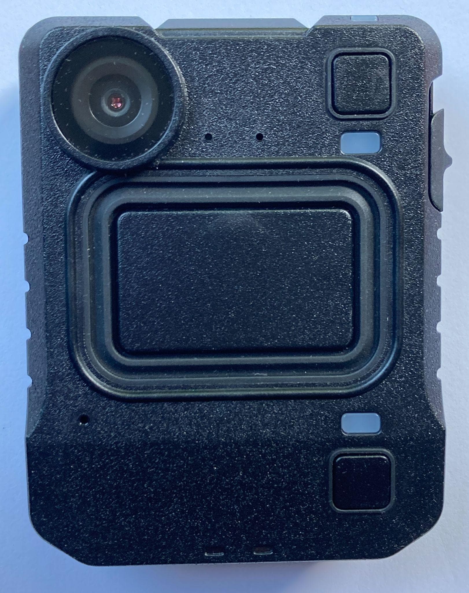
Click to zoom
Application Details
- Equipment Class
- DTS - Digital Transmission System
- Date of Grant
- Sep 20, 2021
- Application Purpose
- Original Equipment
- Date of Application
- Sep 19, 2021
- Equipment Note
- VB400 Body-Worn Camera
- Frequency Range
- 2402.00000000 - 2480.00000000
- Company
- Motorola Solutions, Inc.
- Country
- United States
Documents & Files
Document Text
Text extracted from the exhibit documents filed with the FCC. Open a document above to read the original.
Users Manual
QUICKSTART GUIDE | VB4001 VB400 BODY-WORN CAMERA QUICKSTART GUIDE QUICKSTART GUIDE | VB4002 TABLE OF CONTENTS INTRODUCTION 3 HOW TO CHARGE YOUR VB400 4 CHARGING WITH A 1-PORT DOCK 5 CHARGING WITH A 14-PORT DOCK 6 BATTERY STATUS LED 7 CONFIGURING YOUR VB400 8 IDENTIFYING AN RFID ASSIGNED VB400 9 USING YOUR VB400 10 TO START / STOP RECORDING 10 WEARING YOUR VB400 12 ACCESSORIES 13 REGULATORY INFORMATION 14 QUICKSTART GUIDE | VB4003 INTRODUCTION Thank you for choosing the VB400 Body-worn camera. This simple guide will lead you through the set up and use of your VB400. Lens Buzzer Speaker Function Button A LED LED Function Button C Slider Dual Microphone Front Function Button Function Button B LED QUICKSTART GUIDE | VB4004 HOW TO CHARGE YOUR VB400 Upon receiving your VB400, it is recommended that you fully charge the device before usage. When charging using a 1-Port Dock or 14-Port Dock, insert the camera into the slots as shown below, ensuring the camera clicks securely in place. Check that the top LED blinks green to indicate charging. Slide down to click into place QUICKSTART GUIDE | VB4005 CHARGING WITH A 1-PORT DOCK (VB-400-DOCK-SOLO) Connected to your laptop or DockController. If you are charging your VB400 camera via a 1-Port Dock (VB-400-DOCK-SOLO) your camera will bleep to indicate charging has commenced, and the LED, as indicated, will flash green to show charging. Charging: Flashing green LEDFully Charged: Solid green LED Once fully charged, the same LED will turn solid green. If the LED is not lit, the device is not charging. Your VB400 will be fully charged within 8 hours from a flat battery. QUICKSTART GUIDE | VB4006 CHARGING WITH A 14-PORT DOCK (VB-400-DOCK-14/US) Connected to a power supply and DockController If you are charging your VB400 camera via a 14-Port Dock (VB-400-DOCK-14/US) the top LED will flash green to show charging, and the camera will bleep when successfully connected to VideoManager. Once fully charged, the same LED will turn solid green. If the LED is not lit, the device is not charging. Your VB400 will be fully charged within 8 hours from a flat battery. Charging: Flashing green LEDFully Charged: Solid green LED QUICKSTART GUIDE | VB4007 BATTERY STATUS LED To quickly understand the current battery status of your VB400, press the bottom button on the front face of the camera and refer to the bottom LED. COLOR KEY: Green LED: OK Orange/Yellow LED: Low Red LED: Critical Battery Status Button (Configurable) QUICKSTART GUIDE | VB4008 CONFIGURING YOUR VB400 Prior to using your VB400, your device must be configured and assigned to you using VideoManager. For detailed information on how to configure your device, please refer to the VideoManager User Guide. Each VB400 requires a valid VideoManager License, in order for you to assign devices and access footage. For further details, see the VideoManager User Guide. To ascertain whether your VB400 has been configured, please view the top LED on your device. This LED will turn solid green once configured and assigned. Your VB400 is charged, assigned and ready to use when the LEDs shown are both solid green. Configured, charged & assigned Solid green light PLEASE NOTE: If you try to use your VB400 before it has been assigned, the bottom LED on the front face of the camera will start to flash red and you will hear an alarm tone. You will not be able to use your camera until it has been assigned. QUICKSTART GUIDE | VB4009 IDENTIFYING AN RFID ASSIGNED VB400 Once your device is configured, your system administrator may wish camera users to utilize an RFID system for camera assignment. For further information on assigning VB400s using an RFID reader, please refer to the VideoManager User Guide. Having presented your RFID card, your docked, assigned VB400 will identify itself with a solid red LED as shown. RFID Assigned Camera RFID Reader (RF-220) RFID-Card (RF-CARD-10) QUICKSTART GUIDE | VB40010 USING YOUR VB400 The VB400 series of cameras are intuitive and simple to use. TO START / STOP RECORDING (CONFIGURABLE) Users can activate recording by pressing on the single front button located in the center of the camera as shown. Recording is stopped by pressing and holding the front button. Record activation and deactivation buttons are configurable by Administrators. Start Recording initiated will be indicated by a short bleep, the two upper LEDs showing red. Press center button to start / stop recording Solid red LED QUICKSTART GUIDE | VB40011 Stop Recording initiated is indicated by the two upper LEDs turning from red to off, accompanied by a longer, high pitched bleep. PLEASE NOTE: All buttons are configurable. Please consult with your administrator if you have any issues. Power Down Button (Configurable) No LED QUICKSTART GUIDE | VB40012 WEARING YOUR VB400 The VB400 body-worn camera should always remain upright when capturing footage. QUICKSTART GUIDE | VB40013 ACCESSORIES Designed for optimum performance and comfort in a wide range of situations, the VB400 comes with a variety of fixing types to suit every uniform and body shape. For more information on our range of body-worn cameras, please visit: www.motorolasolutions.com/bwc QUICKSTART GUIDE | VB40014 REGULATORY INFORMATION FCC Responsible party Name: Motorola Solutions, Inc. Address: 2000 Progress Pkway, Schaumburg, Il. 60196 Phone Number: 1-800-927-2744 Hereby declares that the product: Model Name: VB400 Conforms to the following regulations: FCC Part 15, subpart B, section 15.107(a), 15.107(d), and section 15.109(a) This device complies with part 15 of the FCC Rules. Operation is subject to the following two conditions: (1) This device may not cause harmful interference, and (2) this device must accept any interference received, including interference that may cause undesired operation. NOTE: This equipment has been tested and found to comply with the limits for a Class B digital device, pursuant to Part 15 of the FCC Rules. These limits are designed to provide reasona…
Text truncated - open the document above for the full version.
Users Manual
en-US es-LA fr-CA pt-BR RF Energy Exposure Training and Product Safety Information for Mission Critical Devices Formation sur l’exposition aux RF et information sur la sécurité du produit pour appareils essentiels aux missions Capacitación sobre la exposición a energía de radiofrecuencia e información de protección del producto para dispositivos de misión crítica Treinamento sobre a Exposição à energia de RF e Informações de Segurança do Produto para Dispositivos de Missão Crítica https://learning.motorolasolutions.com/User_Documentation English Caution Before using this device, read this booklet which contains important operating instructions. For information on product details, brochures, user manuals and approved accessories. Please refer to www.motorolasolutions.com. Compliance with RF Exposure Standards National and international regulations require manufacturers to comply with the RF energy exposure limits for mission critical devices before they can be marketed. Your Motorola Solutions device is designed, manufactured, and tested to comply with all applicable national and international regulations for human exposure to radio frequency electromagnetic energy. When mission critical devices are used as a consequence of employment, applicable regulations may require users to be fully aware of and able to control their exposure to meet occupational requirements. RF Energy Exposure Awareness and Control Information and Operational Instructions for Occupational Use Notice: This device is intended for use in occupational/ controlled conditions where users are aware of their exposure and can exercise control over their exposure to meet the requirements in national and international regulations. This device is not authorized for general population, consumer use. For more information on what RF energy exposure is, and how to control your exposure to ensure compliance with established RF exposure limits, consult the following websites: •https://www.fcc.gov/ •https://www.osha.gov/ •https://osha.europa.eu/en •http://www.who.int/peh-emf/project/en/ •http://www.ic.gc.ca/eic/site/smt-gst.nsf/eng/sf11467.html •http://www.ic.gc.ca/eic/site/smt-gst.nsf/eng/sf01904.html For additional user training information on exposure requirements, consult the following websites: •https://www.motorolasolutions.com/en_us/about/company-overview/ corporate-responsibility/governance-and-policies/wireless- communication-and-health-faqs.html •http://learning.motorolasolutions.com/ RF Exposure Compliance and Control Guidelines To control your exposure, and ensure compliance with the relevant RF exposure limits, always adhere to the following guidelines: • Do not remove any of the RF Exposure Labels if present from this device or its related accessories. • Attach these instructions to the device when you transfer it to other users. • Do not use this device if the operational requirements described herein are not met. Notice to Users (FCC) This device complies with Part 15 of the FCC rules per the following conditions: • This device may not cause harmful interference. • The device must accept any interference received, including interference that may cause undesired operation. • Changes or modifications made to this device, not expressly approved by Motorola Solutions, could void the authority of the user to operate this equipment. Operating Instructions • If your mission critical device operates similar to a mobile phone then hold your device at your ear when talking on it. • When using the device's speaker to communicate, hold the device in a vertical position in front of the face with the microphone (and other parts of the device) at least one inch (2.5 centimeters) away from the nose and lips. When engaged in Push-To-Talk (PTT) communications, to transmit (talk), press the PTT button. To receive calls, release the PTT button. • When worn on the body, always place the device in a Motorola Solutions approved clip, holder, holster, case, or body harness for this product. Special use cases for Mission Critical Devices English 1 • Fixed Installation: The device operates from a fixed location with at least 20 cm distance between antennas and bystanders. • Mobile Installation: The device operates on a vehicle with at least 20 cm distance between antennas and passangers or bystanders. For these special use cases, transmit only when people (bystanders and/or passengers) are at least at the minimum distance (as shown in Table 1) away from the antennas. This separation will ensure that there is sufficient distance from a properly installed (according to the installation instructions) antenna to satisfy the relevant RF exposure limits. Table 1: Rated Power of Mission Critical Device and Minimum Distance from Antennas Rated Power Minimum Distance of By- standers and Passengers from Antennas Less than 3.5 W8 in. (20 cm) 3.5 to 7 W1 ft (30 cm) 7 to 20 W2 ft (60 cm) 20 to 55 W3 ft (90 cm) • To ensure continued compliance with applicable RF exposure limits, use only Motorola Solutions approved, supplied or replacement batteries, and accessories. • For a list of Motorola Solutions approved accessories please refer to your user manual or visit www.motorolasolutions.com Acoustic Safety Exposure to loud noises from any source for extended periods of time may temporarily or permanently affect your hearing. The louder the volume, the less time is required before your hearing could be affected. Hearing damage from loud noise is sometimes undetectable at first and can have a cumulative effect. To protect your hearing: • Use the lowest volume necessary to do your job. • Turn up the volume only if you are in noisy surroundings. • Turn down the volume before adding headset or earpiece. • Limit the amount of time you use headsets or earpieces at high volume. • When using the device without a headset or earpiece, do not place the loud speaker directly against your ear. Medical Devices If you use a personal medical device, such as a pacemaker or hea…
Text truncated - open the document above for the full version.
Attestation Statements
Applicant: Motorola Solutions IncFCC ID: AZ489FT7148/ IC: 109U-89FT7148 EXHIBIT 2 Statement of Certification (Pursuant to FCC Part 2.907, 2.908 and RSP 100 Sec4) 2.1Statement of Certification Transceivertypedescribedherein(AZ489FT7148/109U-89FT7148)isincompliancewithall applicable parts of the FCC rules and ISED RSS standards. Eachunitmanufactured,imported,ormarketedwillconformtothesamplestestedherein,within thestatisticalvariationsthatcanbeexpectedduetohighvolumeproductionandtest measurement error. NAME:Robin Iddon SIGNATURE: DATE:22 June 2021 TITLE:Director of Engineering Mobile Video EXHIBIT 2 SHEET1OF 2 Applicant: Motorola Solutions IncFCC ID: AZ489FT7148/ IC: 109U-89FT7148 2.2Attestation Statement (Equipment Class DTS and DSS– Bluetooth/WiFi) ThisdevicecontainsanembeddedBluetoothdeviceandWiFidevicethatarecompliantwiththe applicable FCC Part 15C and ISED RSS 247 regulations. Part 15.247 (a)(1) / RSS 247 Section 5.1 ● The hopping sequence must be pseudo random. ● Each frequency must be used equally on the averageby each transmitter ● The receivers input bandwidth is approximately equalto the transmit bandwidth ● The receiver hops in sequence with the transmittedsignal Part 15.247 (g) / RSS 247 Section 5.1 ● Thesystemisdesignedtocomplywithalloftheregulationsinthissectionwhenthe transmitter is presented with a continuous data (orinformation) Part 15.247(h) / RSS 247 Section 5.1 ● Thesystemdoesnotcoordinateitschannelselection/hoppingsequencewithother frequencyhoppingsystemsfortheexpresspurposeofavoidingthesimultaneous occupancy of individual hopping frequencies by multipletransmitters. NAME:Robin Iddon SIGNATURE: DATE:22 June 2021 TITLE:Director of Engineering Mobile Video EXHIBIT 2 SHEET2OF 2
Cover Letter(s)
FCC ID: AZ489FT7148 _______________________________________________________________________________________________________________________ Motorola Solutions Inc. 8000 West Sunrise Boulevard, Fort Lauderdale, Florida 33322 EXHIBIT 13A Date: September 10, 2021 Office of Engineering and Technology Laboratory Division Equipment Authorization Branch Federal Communications Commission Laboratory 7435 Oakland Mills Road Columbia, MD 21046 Subject: Application for Certification of Transmitter with FCC ID: AZ489FT7148 Dear Sir/Madam, Motorola Solutions, Inc (8000 West Sunrise Boulevard, Fort Lauderdale, Florida) herein submits application for Certification of the subject transmitter. This transmitter is intended for use in a body worn camera application operating within the following frequency ranges: Product Name Model Numbers Frequency Range RF Power FCC Rules Part VB400 Body-Worn Camera BTLE 4.0: 2402- 2480MHz 0.40mW (max measured conducted average) 15C VB400V3 BTLE 5.0: 2402- 2480MHz 0.40mW (max measured conducted average) 15C We are requesting certification under Part(s) of the Commission’s Rules listed above to allow operation of this equipment. Note: VB400V3 also includes co-location of the FCC approved module: FCC: VPY LBEE5HY1MW Intermodulation testing has been performed and is compliant. A complete Certification application is enclosed. If you require any additional information, please contact me at (954) 723-4707. Sincerely, ____________________ Deanna Zakharia Regulatory Compliance Manager E-mail: [email protected]
Cover Letter(s)
FCC ID: AZ489FT7148 _______________________________________________________________________________________________________________________ Motorola Solutions Inc. 8000 West Sunrise Boulevard, Fort Lauderdale, Florida 33322 EXHIBIT 13B CONFIDENTIALITY REQUEST September 10, 2021 Office of Engineering and Technology Laboratory Division Equipment Authorization Branch FCC Laboratory 7435 Oakland Mills Road Columbia, MD 21046 Subject: Confidentiality Request for Transmitter with FCC ID: AZ489FT7148 Dear Sir / Madam, Motorola Solutions Inc is requesting that Exhibit 4 (Circuit Descriptions), Exhibit 5 (Schematic Diagrams), Exhibit 10 (Parts List) and Exhibit 12 (Operational Description) not be made routinely available for public inspection. Motorola Solutions Inc considers the information in these exhibits to be classified as trade secrets, pursuant to 47 CFR Section 0.457(d), 0.459 and Section 552(b)(4) of the Freedom of Information Act. Please mark Exhibits 4, 5, 10, and 12 as “Confidential.” Please contact me if you require any additional information. Sincerely, __________________ Deanna Zakharia Regulatory Compliance Manager E-mail: [email protected]
External Photos
Applicant: Motorola Solutions IncFCC ID: AZ489FT7148/ IC: 109U-89FT7148 EXHIBIT 3 EXTERNAL PHOTOGRAPHS (Pursuant to FCC Part 2.1033(b)(7) and 2.1033(c)(12)and RSP 100 Annex C) The following photographs are attached.Exhibit 1.Front View3A 2.Back View (FCC/IC Label Location)3B 3.Side View (Right)3C 4.Side View (Left)3D 5.Top View3E 6.Bottom View3F EXHIBIT 3 SHEET1OF5 Applicant: Motorola Solutions IncFCC ID: AZ489FT7148/ IC: 109U-89FT7148 EXHIBIT 3A: Front View EXHIBIT 3 SHEET2OF5 Applicant: Motorola Solutions IncFCC ID: AZ489FT7148/ IC: 109U-89FT7148 EXHIBIT 3B: Back (FCC/IC Label Location) EXHIBIT 3 SHEET3OF5 Applicant: Motorola Solutions IncFCC ID: AZ489FT7148/ IC: 109U-89FT7148 EXHIBIT 3C: Side View (Right) EXHIBIT 3D: Side View (Left) EXHIBIT 3E: Top View EXHIBIT 3 SHEET4OF5 Applicant: Motorola Solutions IncFCC ID: AZ489FT7148/ IC: 109U-89FT7148 EXHIBIT 3F: Bottom View *** END *** EXHIBIT 3 SHEET5OF5
ID Label/Location Info
Applicant: Motorola Solutions Inc F CC ID: AZ489FT7148/IC: 109U-89FT7148 EXHIBIT 1 IDENTIFICATION LABEL (Pursuant to FCC Part 2.1033(c)(11), 2.1033(b)(7)and RSP 100 Annex C and Sec 3) LOCATION ____See the Attached Photograph or Sketch ____Bottom of Device ____Top of Device _X__Back of Device ____Back of Radio under Belt Clip ____In the Battery Compartment ____Electronic labeling: In the usermanual (Section: XX) TYPE XThe label is a polyester base with polyesteroverlaminate. The adhesive is a permanent type acrylic with the minimum peel strengthof 40 oz/inch MARKINGS (TEXT) XSee the Attached Photograph and Exhibit3 for the actual location of the FCC/IC label on the device. XLabel Attached Below. See Attached Drawing. EXHIBIT 1 SHEET1OF2 Applicant: Motorola Solutions Inc F CC ID: AZ489FT7148/IC: 109U-89FT7148 Figure 1: FCC/IC Label for VB400V3 *** END *** EXHIBIT 1 SHEET2OF2
Internal Photos
Applicant: Motorola Solutions Inc.FCC ID: AZ489FT7148/ IC: 109U-89FT7148 EXHIBIT 9 Internal Photographs (Pursuant to FCC Part 2.1033(b)(7), 2.1033(c)(12) and RSP 100 Annex C) The following photographs are attached.Exhibit 1. Main PCB (Top)9A 2. Main PCB (Bottom)9B 3. Main PCB (Top) with GPS and Sensor Module attached9C 4. Main PCB (Bottom) with GPS and Sensor Module attached9D 5. USB PCB (Top)9E 6. USB PCB (Bottom)9F 7. Main PCB and USB PCB in case9G 8. Internal view with battery fitted9H Exhibit 9 Page |1 Applicant: Motorola Solutions Inc.FCC ID: AZ489FT7148/ IC: 109U-89FT7148 Exhibit 9A - Main PCB (Top) Exhibit 9 Page |2 Applicant: Motorola Solutions Inc.FCC ID: AZ489FT7148/ IC: 109U-89FT7148 Exhibit 9B - Main PCB (Bottom) Exhibit 9 Page |3 Applicant: Motorola Solutions Inc.FCC ID: AZ489FT7148/ IC: 109U-89FT7148 Exhibit 9C - Main PCB (Top) with GPS and Sensor Module attached Exhibit 9 Page |4 Applicant: Motorola Solutions Inc.FCC ID: AZ489FT7148/ IC: 109U-89FT7148 Exhibit 9D - Main PCB (Bottom) with GPS and Sensor Module attached Exhibit 9 Page |5 Applicant: Motorola Solutions Inc.FCC ID: AZ489FT7148/ IC: 109U-89FT7148 Exhibit 9E - USB PCB (Top) Exhibit 9 Page |6 Applicant: Motorola Solutions Inc.FCC ID: AZ489FT7148/ IC: 109U-89FT7148 Exhibit 9F - USB PCB (Bottom) Exhibit 9 Page |7 Applicant: Motorola Solutions Inc.FCC ID: AZ489FT7148/ IC: 109U-89FT7148 Exhibit 9G - Main PCB and USB PCB in case Exhibit 9 Page |8 Applicant: Motorola Solutions Inc.FCC ID: AZ489FT7148/ IC: 109U-89FT7148 Exhibit 9H - Internal view with battery fitted Exhibit 9 Page |9 Applicant: Motorola Solutions Inc.FCC ID: AZ489FT7148/ IC: 109U-89FT7148 *** END *** Exhibit 9 Page |10
RF Exposure Info
This report must not be used to claim product certification, approval, or endorsement by A2LA or any agency of the U.S. Government. This Report shall not be reproduced, except in full without written approval of the laboratory. Motorola Solutions VB400V3 SAR Evaluation Report: ELEM0125 Rev. 1, Issue Date: September 1, 2021 Evaluated to the following SAR specification: FCC 2.1093:2021 CERTIFICATE OF TEST 2018-07-17 Last Date of Test: August 3, 2021 Motorola Solutions EUT: VB400V3 Applicable Standard: Test Description Specification Test Method Pass/Fail SAR Evaluation FCC 2.1093:2021 IEEE Std 1528:2013 FCC KDB 865664 D01 v01r04 FCC KDB 865664 D02 v01r02 FCC KDB 447498 D01 v06 KDB 248227 D01 v02r02 Pass Highest Measured SAR Values: Radio Equipment Class Frequency Band (MHz) Body (W/kg) Limit (W/kg) Exposure Environment 1g 1g Bluetooth DSS 2402-2480 0.03 1.6 General Population Wi-Fi 802.11b/g/n DTS 2412-2462 0.34 1.6 Wi-Fi 802.11a/n NII 5180-5240 Reduced 1.6 5260-5320 0.09 1.6 Highest Simultaneous SAR Values: Radios Combined Body (W/kg) Limit (W/kg) Exposure Environment 1g 1g Bluetooth Low Energy*, Wi-Fi 802.11b/g/n 0.38 1.6 General Population *The SAR value for Bluetooth Low Energy is an estimated SAR value. Deviations From Test Standards None Approved By: Don Facteau, Systems Architect Report No. ELEM0125 Rev. 12/78 REVISION HISTORY 2018.07.17 Revision Number Description Date (yyyy-mm-dd) Page Number 01 Updated lab accreditation from NVLAP to A2LA 2021-09-01 1, 4, 5 Report No. ELEM0125 Rev. 13/78 ACCREDITATIONS AND AUTHORIZATIONS 2021.09.01 United States FCC - Designated by the FCC as a Telecommunications Certification Body (TCB). Certification chambers, Open Area Test Sites, and conducted measurement facilities are listed with the FCC. A2LA - Each laboratory is accredited by A2LA to ISO / IEC 17025, and as a product certifier to ISO / IEC 17065 which allows Element to certify transmitters to FCC and IC specifications. Canada ISED - Recognized by Innovation, Science and Economic Development Canada as a Certification Body (CB) and as a CAB for the acceptance of test data. European Union European Commission – Recognized as an EU Notified Body validated for the EMCD and RED Directives. United Kingdom BEIS – Recognized by the UK as an Approved Body under the UK Radio Equipment and UK EMC Regulations. Australia/New Zealand ACMA - Recognized by ACMA as a CAB for the acceptance of test data. Korea MSIT / RRA - Recognized by KCC’s RRA as a CAB for the acceptance of test data. Japan VCCI - Associate Member of the VCCI. Conducted and radiated measurement facilities are registered. Taiwan BSMI – Recognized by BSMI as a CAB for the acceptance of test data. NCC - Recognized by NCC as a CAB for the acceptance of test data. Singapore IDA – Recognized by IDA as a CAB for the acceptance of test data. Israel MOC – Recognized by MOC as a CAB for the acceptance of test data. Hong Kong OFCA – Recognized by OFCA as a CAB for the acceptance of test data. Vietnam MIC – Recognized by MIC as a CAB for the acceptance of test data. SCOPE For details on the Scopes of our Accreditations, please visit: California Minnesota Oregon Texas Washington Report No. ELEM0125 Rev. 14/78 FACILITIES 2020.12.15 California Labs OC01-17 41 Tesla Irvine, CA 92618 (949) 861-8918 Minnesota Labs MN01-11 9349 W Broadway Ave. Brooklyn Park, MN 55445 (612)-638-5136 Oregon Labs EV01-12 6775 NE Evergreen Pkwy #400 Hillsboro, OR 97124 (503) 844-4066 Texas Labs TX01-09 3801 E Plano Pkwy Plano, TX 75074 (469) 304-5255 Washington Labs NC01-05 19201 120 th Ave NE Bothell, WA 98011 (425)984-6600 A2LA Lab Code: 3310.04 Lab Code: 3310.05 Lab Code: 3310.02 Lab Code: 3310.03 Lab Code: 3310.06 Innovation, Science and Economic Development Canada 2834B-1, 2834B-3 2834E-1, 2834E-3 2834D-1 2834G-1 2834F-1 BSMI SL2-IN-E-1154R SL2-IN-E-1152R SL2-IN-E-1017 SL2-IN-E-1158R SL2-IN-E-1153R VCCI A-0029 A-0109 A-0108 A-0201 A-0110 Recognized Phase I CAB for ISED, ACMA, BSMI, IDA, KCC/RRA, MIC, MOC, NCC, OFCA US0158 US0175 US0017 US0191 US0157 Report No. ELEM0125 Rev. 15/78 PRODUCT DESCRIPTION 2014-12-10 Client and Equipment Under Test (EUT) Information Company Name: Motorola Solutions Address: Motorola Solutions, Caledonian Exchange, 19A Canning Street City, State, Zip: Edinburgh, EH3 8EG, UK Test Requested By: Anne Ambler Model: VB400V3 First Date of Test: April 20, 2021 Last Date of Test: August 3, 2021 Receipt Date of Samples: February 23, 2021 Equipment Design Stage: Preproduction Equipment Condition: No Damage Purchase Authorization: Verified Information Provided by the Party Requesting the Test Functional Description of the EUT: The VB400V3 is a body-worn camera containing a combination 802.11a/b/g/n and Bluetooth radio. It also contains a standalone BLE radio. The VB400V3 can attach to clothing or harnesses via various accessories. Contains FCC IDs: VPYLBEE5HY1MW, AZ489FT7148 The device contains the following radios: 802.11b/g/n: 2412-2462 MHz 802.11a/n: 5180-5320 MHz Bluetooth: 2402-2480 MHz Bluetooth Low Energy: 2402-2480 MHz Location of transmit antenna(s): 802.11a/b/g/n and Bluetooth Combination Antenna Bluetooth Low Energy Antenna Report No. ELEM0125 Rev. 16/78 PRODUCT DESCRIPTION 2014-12-10 Testing Locations and Separation Distances: Accessory Technology EUT Orientation Front Back Left Right Top Bottom None Bluetooth BDR/EDR Reduced 4 0 mm Reduced 4 Reduced 4 Reduced 4 Reduced 4 Bluetooth LE Reduced 3 Reduced 3 Reduced 3 Reduced 3 Reduced 3 Reduced 3 802.11b/g/n DSSS Reduced 4 0 mm Reduced 4 Reduced 4 Reduced 4 Reduced 4 802.11b/g/n OFDM Reduced 1 Reduced 1 Reduced 1 Reduced 1 Reduced 1 Reduced 1 802.11a/n U-NII-1 Reduced 2 Reduced 2 Reduced 2 Reduced 2 Reduced 2 Reduced 2 802.11a/n U-NII-2A Reduced 4 0 mm Reduced 4 Reduced 4 Reduced 4 Reduced 4 MagMount 5 Bluetooth BDR/EDR Reduced 4 0 mm Reduced 4 Reduced 4 Reduced 4 Reduced 4 Bluetooth LE Reduced 3 Reduced 3 Reduced 3 Reduced 3 Reduced 3 Reduced 3 802.11b/g/n DSSS Reduced 4 0 mm Reduced 4 Reduced 4 Red…
Text truncated - open the document above for the full version.
RF Exposure Info
Report No. ELEM0125 Rev. 139/78 Report No. ELEM0125 Rev. 140/78 Report No. ELEM0125 Rev. 141/78 Report No. ELEM0125 Rev. 142/78 Report No. ELEM0125 Rev. 143/78 Report No. ELEM0125 Rev. 144/78 Report No. ELEM0125 Rev. 145/78 Report No. ELEM0125 Rev. 146/78
RF Exposure Info
PsaCal 2020.06.10.0 DUT Code:ADLCal Date:2020-11-09 DescriptionAntenna - DipoleTemperature:20.4C ModelD2450V2Humidity:37.80% ManufacturerSPEAGTester:Kyle McMullanPressure:1012.6mb Certificate No.:ADL2020-11-09Job Site:MN11 TEST SPECIFICATIONS Specification:Version: Specification:Version: TEST PARAMETERS Device Received In Tolerance:YesNext Cal Due Date: Item:Identifier:NAMModel:Last Cal:2019-11-13Cal Due:2022-11-13 Item:Identifier:NANModel:Last Cal:NCRCal Due:NCR Item:Identifier:NANAModel:Last Cal:2020-09-10Cal Due:2021-09-10 Item:Identifier: Model:Last Cal: Cal Due: Item:Identifier: Model:Last Cal: Cal Due: Item:Identifier: Model:Last Cal: Cal Due: COMMENTS, OPINIONS and INTERPRETATIONS Measurement Uncertainty RESULTS Pass Measurements are traceable to the International System of Units (SI) via NIST. CALIBRATION DATA ATTACHED normal (k=2) 0.81 Probability Distribution Impedance (dB) Value (+/- %) calibration verification. (Instrument parameters are within tolerances.) Value (dB)Insertion Loss (dB) This measurement was a Expanded uncertainty U (level of confidence = 95%) None Fixture/Kit - Calibration/Verification Terminator Analyzer - Network Analyzer 85032F 85032-60017 Calibration Report for Antenna - Dipole Equipment Used to perform calibration Calibrated Frequency Range:N/A 2020 - Rev 0WP 438 SAR Dipole Verificaiton E5071C 2021-11-10 Report No. ELEM0125 Rev. 147/78 Return Loss Real Impedence Imaginary Impedence 2020 Value (dB) -26.32020 Value (Ω)52.03.5 2019 Value (dB) -24.7 2019 Value (Ω) 52.25.6 Deviation (%) -6.5 Deviation (Ω) 0.22.1 Limit (%) 20 Limit (Ω) 55 Limit (< dB) -20 Results PassPass Results Pass 2020 Value (dB) -24.22020 Value (Ω)48.31.8 2019 Value (dB) -23.3 2019 Value (Ω) 496.7 Deviation (%) -3.9 Deviation (Ω) 0.74.9 Limit (%) 20 Limit (Ω) 55 Limit (< dB) -20 Results PassPass Results Pass Body Phantom Head Phantom Report No. ELEM0125 Rev. 148/78
RF Exposure Info
Report No. ELEM0125 Rev. 149/78 Report No. ELEM0125 Rev. 150/78 Report No. ELEM0125 Rev. 151/78 Report No. ELEM0125 Rev. 152/78 Report No. ELEM0125 Rev. 153/78 Report No. ELEM0125 Rev. 154/78 Report No. ELEM0125 Rev. 155/78 Report No. ELEM0125 Rev. 156/78 Report No. ELEM0125 Rev. 157/78 Report No. ELEM0125 Rev. 158/78 Report No. ELEM0125 Rev. 159/78 Report No. ELEM0125 Rev. 160/78 Report No. ELEM0125 Rev. 161/78 Report No. ELEM0125 Rev. 162/78 Report No. ELEM0125 Rev. 163/78 Report No. ELEM0125 Rev. 164/78
RF Exposure Info
PsaCal 2020.06.10.0 DUT Code:ADMCal Date:2020-11-09 DescriptionAntenna - DipoleTemperature:20.4C ModelD5GHzV2Humidity:37.80% ManufacturerSPEAGTester:Kyle McMullanPressure:1012.6mb Certificate No.:ADM2020-11-09Job Site:MN11 TEST SPECIFICATIONS Specification:Version: Specification:Version: TEST PARAMETERS Device Received In Tolerance:YesNext Cal Due Date: Item:Identifier:NAMModel:Last Cal:2019-11-13Cal Due:2022-11-13 Item:Identifier:NANModel:Last Cal:NCRCal Due:NCR Item:Identifier:NANAModel:Last Cal:2020-09-10Cal Due:2021-09-10 Item:Identifier: Model:Last Cal: Cal Due: Item:Identifier: Model:Last Cal: Cal Due: Item:Identifier: Model:Last Cal: Cal Due: COMMENTS, OPINIONS and INTERPRETATIONS Measurement Uncertainty RESULTS Pass Measurements are traceable to the International System of Units (SI) via NIST. Calibration Report for Antenna - Dipole Equipment Used to perform calibration Calibrated Frequency Range:N/A 2020 - Rev 0WP 438 SAR Dipole Verificaiton E5071C 2021-11-10 None Fixture/Kit - Calibration/Verification Terminator Analyzer - Network Analyzer 85032F 85032-60017 CALIBRATION DATA ATTACHED normal (k=2) 0.81 Probability Distribution Impedance (dB) Value (+/- %) calibration verification. (Instrument parameters are within tolerances.) Value (dB)Insertion Loss (dB) This measurement was a Expanded uncertainty U (level of confidence = 95%) Report No. ELEM0125 Rev. 16…
Text truncated - open the document above for the full version.
Contact Information
Applicant
Arine Lee(Certification Manager)
Test Firm
Element Materials Technology Warwick LtdNeil Roche
Technical Specifications
| # | Rule Parts | Frequency Range | Power Output |
|---|---|---|---|
| 1 | 15C | 2.40 GHz - 2.48 GHz | 400.00 µW |
Other Applications from Motorola Solutions, Inc.

AZ489FT4980
Sep 08, 2026Portable two way radio
Equipment Class
TNF - Licensed Non-Broadcast Transmitter Held to FaceAZ489FT4981
Aug 14, 2026Handheld Portable - TANAPA BPR 45 400-470 MHZ 4W NKP
Equipment Class
TNF - Licensed Non-Broadcast Transmitter Held to Face
AZ489FT7187
Jul 13, 2026Portable 2-Way Radio with Bluetooth, Bluetooth LE, WIFI 2.4GHz, WIFI 5GHz, LTE
Equipment Class
DSS - Part 15 Spread Spectrum TransmitterAZ499FT6031
May 11, 2026Operation Critical Wireless Earpiece PTT
Equipment Class
DSS - Part 15 Spread Spectrum Transmitter
AZ499FT5879
Dec 19, 20252-way Portable Radio with BT, BTLE, WIFI, NFC and LTE
Equipment Class
DSS - Part 15 Spread Spectrum Transmitter