AZ492FT1627Mobile Transmitter
Motorola Solutions, Inc.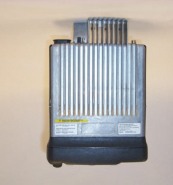
Click to zoom
Application Details
- Equipment Class
- TNB - Licensed Non-Broadcast Station Transmitter
- Date of Grant
- Aug 30, 2000
- Application Purpose
- Original Equipment
- Date of Application
- Mar 23, 2000
- Equipment Note
- Mobile Transmitter
- Frequency Range
- 29.70000000 - 36.00000000
- Company
- Motorola Solutions, Inc.
- Country
- United States
Documents & Files
Document Text
Text extracted from the exhibit documents filed with the FCC. Open a document above to read the original.
Users Manual
1 English CONTENTS CONTENTS Computer Software Copyrights . . . . . . . . . . 3 Radio Overview . . . . . . . . . . . . . . . . . . . . . 5 Parts of the Radio . . . . . . . . . . . . . . . . . . . . 5 Optional Enhanced DTMF (Keypad) Microphone (RMN4026) . . . . . . . . . . . 6 On/Off/Volume Knob . . . . . . . . . . . . . . . 7 Channel Selector/Menu Navigation Buttons . . . . . . . . . . . . . . . . . . . . . . . . 7 LED Indicators . . . . . . . . . . . . . . . . . . . . 7 Programmable Buttons . . . . . . . . . . . . . 7 Push-to-Talk (PTT) Button . . . . . . . . . . 10 Microphone . . . . . . . . . . . . . . . . . . . . . 10 Menu Keys . . . . . . . . . . . . . . . . . . . . . . 10 Use with Optional Enhanced DTMF Microphone (RMN4026) . . . . . . . . . . 11 LCD Screen . . . . . . . . . . . . . . . . . . . . . 13 Audio Indicators for Programmable Buttons . . . . . . . . . . . . . . . . . . . . . . . . . . 14 Getting Started . . . . . . . . . . . . . . . . . . . . 15 Turning the Radio On or Off . . . . . . . . . . . 15 Adjusting the Volume . . . . . . . . . . . . . . . . 15 Selecting a Zone . . . . . . . . . . . . . . . . . . . . 16 Selecting a Radio Channel . . . . . . . . . . . . 16 Sending a Call . . . . . . . . . . . . . . . . . . . . . 17 Receiving a Call . . . . . . . . . . . . . . . . . . . . 17 Radio Calls . . . . . . . . . . . . . . . . . . . . . . . 19 Making a Selective Call . . . . . . . . . . . . . . 19 Receiving a Selective Call . . . . . . . . . . . . 19 Sending a Call Alert™ Page . . . . . . . . . . . 20 Receiving a Call Alert Page . . . . . . . . . . . 20 Radio Check . . . . . . . . . . . . . . . . . . . . . . . 21 Sending a Status . . . . . . . . . . . . . . . . . . . 21 Sending a Message . . . . . . . . . . . . . . . . . 22 Receiving a Message . . . . . . . . . . . . . . . . 23 Sending an Emergency Alert . . . . . . . . . . 23 Receiving Selective Radio Inhibit . . . . . . . 24 Editing a Radio Call List . . . . . . . . . . . . . . 24 Repeater or Talkaround Mode . . . . . . . . . 25 Setting the Power Level . . . . . . . . . . . . . . 25 Name and Call/Message Tone Tagging . . 26 Scan . . . . . . . . . . . . . . . . . . . . . . . . . . . . . 29 Starting or Stopping Scan. . . . . . . . . . . . . 29 Talkback . . . . . . . . . . . . . . . . . . . . . . . . . . 30 Deleting a Nuisance Channel . . . . . . . . . . 30 Restoring a Channel to the Scan List . 30 2 English CONTENTS Editing a Scan List . . . . . . . . . . . . . . . . . . 30 Adding or Deleting Channels in a Scan List . . . . . . . . . . . . . . . . . . . . . 31 Prioritizing a Channel in a Scan List . . 32 Setting Priority Channels . . . . . . . . . . . 32 Phone. . . . . . . . . . . . . . . . . . . . . . . . . . . . 35 Making a Phone Call . . . . . . . . . . . . . . . . 35 Modifying the Phone List . . . . . . . . . . . . . 36 Adding an Entry (when using the keypad microphone only) . . . . . . 36 Deleting an Entry: . . . . . . . . . . . . . . . . 37 Editing an Entry (when using the keypad microphone only) . . . . . . 38 Editing an Access/Deaccess Code (when using the keypad microphone only) . . . . . . . . . . . . . . . . . . . . . . . . . 39 Audio/Tone Settings. . . . . . . . . . . . . . . . 41 Utilities. . . . . . . . . . . . . . . . . . . . . . . . . . . 43 Setting the Time . . . . . . . . . . . . . . . . . . . . 45 Displaying the Time . . . . . . . . . . . . . . . . . 46 Selecting the Display Language . . . . . . . . 46 Safety and Warranty . . . . . . . . . . . . . . . 47 Safe and Efficient Operation of Motorola Two-Way Radios . . . . . . . . . . . . . . . . . . 47 Exposure to Radio Frequency Energy. . . . . . . . . . . . . . . . . . . . . . . . . 47 Electromagnetic Interference/ Compatibility . . . . . . . . . . . . . . . . . . . . . 48 Operational Warnings . . . . . . . . . . . . . . . 48 Vehicles with an Air Bag . . . . . . . . . . . 48 Potentially Explosive Atmospheres . . . 48 Blasting Caps and Blasting Areas. . . . 49 Mobile Radio Operation and EME Exposure . . . . . . . . . . . . . . . . . . . . . 49 Mobile Antenna Installation . . . . . . . . . 50 Control Station Operation. . . . . . . . . . . . . 50 Limited Warranty . . . . . . . . . . . . . . . . . . . 50 Accessories . . . . . . . . . . . . . . . . . . . . . . 55 Audio . . . . . . . . . . . . . . . . . . . . . . . . . . . . 55 Mounting . . . . . . . . . . . . . . . . . . . . . . . . . 55 Antennas . . . . . . . . . . . . . . . . . . . . . . . . . 56 Control Station . . . . . . . . . . . . . . . . . . . . . 56 3 English CONTENTS COMPUTER SOFTWARE COPYRIGHTS The Motorola products described in this manual may include copyrighted Motorola computer programs stored in semiconductor memories or other media. Laws in the United States and other countries preserve for Motorola certain exclusive rights for copyrighted computer programs including, but not limited to, the exclusive right to copy or reproduce in any form the copyrighted computer program. Accordingly, any copyrighted Motorola computer programs contained in the Motorola products described in this manual may not be copied, reproduced, modified, reverse-engineered, or distributed in any manner without the express written permission of Motorola. Furthermore, the purchase of Motorola products shall not be deemed to grant either directly or by implication, estoppel, or otherwise, any license under the copyrights, patents or patent applications of Motorola, except for the normal non-exclusive license to use that arises by operation of law in the sale of a product. 4 English CONTENTS Notes 5 English RADIO OVERVIEW RADIO OVERVIEW PARTS OF THE RADIO Editing Buttons Menu Enter/Select Button (Interchangeable) Programmable Button 2 (P2) (Interchangeable) Programmable Button 4 (P4) (Interchangeable) Programmable Button 3 (P3) LCD Screen Red/Yellow/Green LED Indicators Menu Exit/Escape Button (Interchangeable) Programmable Button 1 (P1) (Left/Right) Microphone Jack Knob On/Off/Volume Channel Selector/ Menu Navigation Buttons (Up/…
Text truncated - open the document above for the full version.
Users Manual
i English CONTENTS CONTENTS Computer Software Copyrights . . . . . . . . . . iii Radio Overview . . . . . . . . . . . . . . . . . . . . 1 Parts of the Radio . . . . . . . . . . . . . . . . . . . 1 Optional Enhanced Keypad Microphone (RMN4026) . . . . . . . . . 2 On/Off/Volume Knob . . . . . . . . . . . . . . 3Channel Selector/Menu Navigation Buttons . . . . . . . . . . . . . . . . . . . . . . 3 LED Indicators . . . . . . . . . . . . . . . . . . . 3Programmable Buttons . . . . . . . . . . . . 3Push-to-Talk (PTT) Button . . . . . . . . . . 6Microphone . . . . . . . . . . . . . . . . . . . . . 6Menu Keys . . . . . . . . . . . . . . . . . . . . . . 6Use with Enhanced Keypad Microphone (RMN4026) . . . . . . . . . 7 LCD Screen . . . . . . . . . . . . . . . . . . . . . 9 Audio Indicators for Programmable Buttons. . . . . . . . . . . . . . . . . . . . . . . . . 10 Getting Started . . . . . . . . . . . . . . . . . . . 11 Turning the Radio On or Off . . . . . . . . . . 11Adjusting the Volume . . . . . . . . . . . . . . . 11Selecting a Zone . . . . . . . . . . . . . . . . . . . 12Selecting a Radio Channel . . . . . . . . . . . 12 Sending a Call . . . . . . . . . . . . . . . . . . . . . 13Receiving a Call . . . . . . . . . . . . . . . . . . . . 13 Radio Calls . . . . . . . . . . . . . . . . . . . . . . . 15 Making a Selective Call . . . . . . . . . . . . . . 15Receiving a Selective Call . . . . . . . . . . . . 15Sending a Call Alert™ Page. . . . . . . . . . . 16Receiving a Call Alert Page . . . . . . . . . . . 16Radio Check . . . . . . . . . . . . . . . . . . . . . . . 17Sending a Status . . . . . . . . . . . . . . . . . . . 17Sending a Message . . . . . . . . . . . . . . . . . 18Receiving a Message . . . . . . . . . . . . . . . . 19Sending an Emergency Alert . . . . . . . . . . 19Selective Radio Inhibit . . . . . . . . . . . . . . . 20Editing a Radio Call List . . . . . . . . . . . . . . 20Repeater or Talkaround Mode . . . . . . . . . 21Setting the Power Level . . . . . . . . . . . . . . 21Name and Call/Message Tone Tagging . . 22 Scan . . . . . . . . . . . . . . . . . . . . . . . . . . . . . 25 Starting or Stopping Scan. . . . . . . . . . . . . 25Talkback . . . . . . . . . . . . . . . . . . . . . . . . . . 26Deleting a Nuisance Channel . . . . . . . . . . 26 Restoring a Channel to the Scan List . 26 Editing a Scan List . . . . . . . . . . . . . . . . . . 26 Adding or Deleting Channels in a Scan List . . . . . . . . . . . . . . . . . 27 ii English CONTENTS Prioritizing a Channel in a Scan List . . 28Setting Priority Channels . . . . . . . . . . . 28 Phone. . . . . . . . . . . . . . . . . . . . . . . . . . . . 31 Making a Phone Call . . . . . . . . . . . . . . . . 31Modifying the Phone List . . . . . . . . . . . . . 32 Adding an Entry (when using the enhanced keypad microphone only). . . . . . . . . . . . . . . 32 Deleting an Entry . . . . . . . . . . . . . . . . . 33Editing an Entry (when using the enhanced keypad microphone only). . . . . . . . . . . . . . . 34 Editing an Access/Deaccess Code (when using the enhanced keypad microphone only). . . . . . . . . . . . . . . 35 Audio/Tone Settings. . . . . . . . . . . . . . . . 37Utilities. . . . . . . . . . . . . . . . . . . . . . . . . . . 39 Setting the Time . . . . . . . . . . . . . . . . . . . . 41Displaying the Time . . . . . . . . . . . . . . . . . 42Selecting the Display Language . . . . . . . . 42 Safety and Warranty . . . . . . . . . . . . . . . . 43 Safe and Efficient Operation of Motorola Two-Way Radios . . . . . . . . . . . . . . . . . . 43 Exposure to Radio Frequency Energy . . . . . . . . . . . . . . . . . . . . . . 43 Mobile Radio Operation and EME Exposure . . . . . . . . . . . . . . . . 44 Electromagnetic Interference/ Compatibility . . . . . . . . . . . . . . . . . . 44 Operational Warnings . . . . . . . . . . . . . . . 45 Vehicles with an Air Bag . . . . . . . . . . . 45Potentially Explosive Atmospheres . . . 45Blasting Caps and Blasting Areas. . . . 45 ANTENNA INSTALLATION . . . . . . . . . . . 46 MOBILE ANTENNAS . . . . . . . . . . . . . 46FIXED SITE ANTENNAS . . . . . . . . . . 46 Limited Warranty . . . . . . . . . . . . . . . . . . . 47 Accessories . . . . . . . . . . . . . . . . . . . . . . 51 Audio . . . . . . . . . . . . . . . . . . . . . . . . . . . . 51Mounting . . . . . . . . . . . . . . . . . . . . . . . . . 51Antennas . . . . . . . . . . . . . . . . . . . . . . . . . 52Control Station . . . . . . . . . . . . . . . . . . . . . 52 iii English CONTENTS COMPUTER SOFTWARECOPYRIGHTS The Motorola products described in this manual may include copyrighted Motorola computer programs stored in semiconductor memories or other media. Laws in the United States and other countries preserve for Motorola certain exclusive rights for copyrighted computer programs including, but not limited to, the exclusive right to copy or reproduce in any form the copyrighted computer program. Accordingly, any copyrighted Motorola computer programs contained in the Motorola products described in this manual may not be copied, reproduced, modified, reverse-engineered, or distributed in any manner without the express written permission of Motorola. Furthermore, the purchase of Motorola products shall not be deemed to grant either directly or by implication, estoppel, or otherwise, any license under the copyrights, patents or patent applications of Motorola, except for the normal non-exclusive license to use that arises by operation of law in the sale of a product. iv English CONTENTS 1 English RADIO OVERVIEW RADIO OVERVIEW PARTS OF THE RADIO Editing Buttons Menu Enter/Select Button (Interchangeable) Programmable Button 2 (P2) (Interchangeable) Programmable Button 4 (P4) (Interchangeable) Programmable Button 3 (P3) LCD Screen Red/Yellow/GreenLED Indicators Menu Exit/Escape Button (Interchangeable) Programmable Button 1 (P1) (Left/Right) Microphone Jack Knob On/Off/Volume Channel Selector/Menu Navigation Buttons(Up/Down) 2 English RADIO OVERVIEW Optional Enh…
Text truncated - open the document above for the full version.
Users Manual
i Section1 Radio Installation Table of Contents Chapter 1.1 Safety Information SAFE AND EFFICIENT OPERATION OF MOTOROLA TWO-WAY RADIOS ............. 1.1-1 EXPOSURE TO RADIO FREQUENCY ENERGY ............................................................. 1.1-1 PORTABLE RADIO OPERATION AND EME EXPOSURE ............................................. 1.1-1 ELECTROMAGNETIC INTERFERENCE/COMPATIBILITY .......................................... 1.1-2 OPERATIONAL WARNINGS ............................................................................................. 1.1-2 OPERATIONAL CAUTIONS............................................................................................... 1.1-2 MOBILE RADIO OPERATION AND EME EXPOSURE .................................................. 1.1-3 ANTENNA INSTALLATION .............................................................................................. 1.1-3 Chapter 1.2 Introduction 1.2.1 General Information ....................................................................................... 1.2-4 1.2.2 Plan the Installation........................................................................................ 1.2-4 Chapter 1.3 DC Power Cable Installation 1.3.1 Planning the Power Cable Installation ........................................................... 1.3-5 1.3.2 Power Cable Installation Procedure............................................................... 1.3-5 Chapter 1.4 Trunnion Installation 1.4.1 Planning the Mounting Trunnion Installation .................................................. 1.4-8 1.4.2 Trunnion Installation Procedure ..................................................................... 1.4-8 1.4.3 Control Head Mounting Position .................................................................... 1.4-9 Chapter 1.5 Antenna Installation 1.5.1 Mobile Radio Operation and EME Exposure ............................................... 1.5-10 1.5.2 Selecting an Antenna Site............................................................................ 1.5-10 1.5.3Mobile Antennas............................................................................. 1.5-10 1.5.4Fixed Site Antennas ....................................................................... 1.5-11 1.5.5 Antenna Installation Procedure .................................................................... 1.5-11 1.5.6 Completing the Installation........................................................................... 1.5-12 ii Chapter 1.6 Installation Options 1.6.1 Radio Mounting in Dashboard ......................................................................1.6-14 1.6.2 External Speaker Installation........................................................................1.6-15 1.6.3 Remote Control Head Installation.................................................................1.6-16 1.6.3.1 Removing the Front Housing ..........................................................1.6-16 1.6.3.2 Assembling the Remote Front Housing ..........................................1.6-16 1.6.3.3 Assembling the Remote Back Housing...........................................1.6-16 1.6.3.4 Installing the Remote Control Head ................................................1.6-16 Chapter 1.7 Accessory Connections 1.7.1 Accessory Connector Pin Functions.............................................................1.7-18 1.7.2 Connection Plan for Accessories..................................................................1.7-20 A 6881092C58-O General: The following installation suggestions and test procedures are recommended for vehicles with electronic anti- lock/anti-skid brakes. Refer to your vehicle service manual for your vehicle’s braking system, or contact your dealer directly. INSTALLATION WARNINGS: Disruption of the anti-skid/anti-lock braking system by the radio transmitter may result in unexpected vehicle motion. Motorola recommends the following radio installation precautions and vehicle braking system test procedures to ensure that the radio, when transmitting, does not interfere with the operation of the vehicle braking system. INSTALLATION PRECAUTIONS: 1.Always provide as much distance as possible between the braking modulator unit and the radio, the radio antenna, and associated transmission line. Before installing the radio, determine the location of the brak- ing modulator unit in the vehicle. Depending on the make and model of the vehicle, the braking modulator unit may be located in the trunk, under the dashboard, in the engine compartment, or in some other cargo area. If you cannot determine the location of the braking modulator unit, refer to the vehicle service man- ual or contact a dealer for the particular make of the vehicle. 2.If the braking modular unit is located on the left side of the vehicle, install the radio on the right side of the vehicle, and conversely. 3.Route all radio wiring, including the antenna transmission line, as far away as possible from the braking modular unit and associated braking system wiring. 4.Never activate the radio transmitter while the vehicle is in motion and the vehicle trunk lid is open. BRAKING SYSTEM TESTS: Be sure the following vehicle testing is done in an isolated area. The following procedure checks for the most common types of interference that may be caused by a radio transmitter to vehicle braking system: 1.Run the vehicle engine at idle speed and set the vehicle transmission selector to PARK. Release the brake pedal completely and key the radio transmitter. While NOT speaking into the microphone, verify that there are no unusual effects (visual or audible) to the vehicle lights, or other electrical equipment and accesso- ries. 2.Repeat Step 1, except do so while speaking into the microphone. 3.Press the vehicle brake pedal slightly; just enough to illuminate the vehicle brake light(s). Then repeat Steps 1 and 2. 4.Press the vehicle brake pedal firmly and repeat Steps 1 and 2. 5.Ensure that there is a minimum of two …
Text truncated - open the document above for the full version.
Attestation Statements
MOTOROLA INCFCC ID: AZ492FT1627 EXHIBIT 2 SHEET 1 OF 1 CERTIFICATION OF DATA The technical data supplied with this application, having been taken under my supervision is hereby duly certified. The following is a statement of my qualifications: 1) I have received a BSEE degree in Electrical Engineering from Northwestern University, Evanston, Illinois. 2) I have 27 years experience in developing, testing and certifying Land Mobile Communications Products. NAME: James M. Zima SIGNATURE: James M. Zima DATE: March 16, 2000 POSITION: Senior Staff Engineer I hereby certify that the above application was prepared under my direction and that to the best of my knowledge and belief, the facts set forth in the application and accompanying technical data are true and correct: NAME: Robert M. Kraus SIGNATURE: Robert M. Kraus DATE:March 16, 2000 POSITION: Engineering Section Manager
Block Diagram
MOTOROLA INC.FCC ID: AZ492FT1627 EXHIBIT 4 SHEET 1 OF 2 CIRCUIT DESCRIPTIONS EXHIBIT 4A – MEANS FOR FREQUENCY STABILIZATION Frequency stability is maintained by a reference oscillator/programmable temperature compensation circuit located in the frequency synthesizer IC U1201. The oscillator is a Colpitts design with an amplifier in the IC. The 16.8 MHz crystal Y1201, varactor CR1201, and feedback capacitors are external circuitry. A control voltage applied to the varactor via the programmable compensation circuit within U1201maintains the frequency stability to within +/-2.5 ppm over the specified operating temperature range. Frequency tuning, also from the programmable compensation circuit, has 128 steps of resolution. Each 16.8 MHz crystal is numerically coded providing its unique characteristic over the operating temperature range. With the crystal temperature characteristic known, a computed compensation characteristic is programmed into the compensation algorithm. EXHIBIT 4B – MEANS FOR LIMITING MODULATION Modulation limiting is accomplished within the custom IC, U0221. The limiting action itself occurs at the rails (i.e., 5V and ground). Using an opamp with feedback, very hard limiting is obtained. The limited modulation signal is then applied to a low-pass splatter filter, and then to an electronic attenuator within U0221 in order to adjust for variations in modulation sensitivities of the frequency synthesizer. The electronic attenuator is controlled by the radio’s microprocessor, U0101. To keep the deviation constant over the RF frequency range & channel bandwidth, the microcomputer adds the proper correction factor to the attenuator. EXHIBIT 4C – MEANS FOR ATTENUATION OF HIGHER AUDIO FREQUENCIES The output of the limiter is applied to a low-pass splatter filter. This filter is a fifth-order switched capacitor filter with the roll-off corner located at 3000 Hz. The output of the low-pass filter is applied to the electronic attenuator before being routed to the modulator. EXHIBIT 4D – MEANS FOR ATTENUATION OF SPURIOUS EMISSIONS The final stage of the RF power amplifier circuit feeds a low-pass filter in order to attenuate harmonics of the carrier frequency as well as any spurious signals. The filter is a seven-pole elliptic design using LC lumped elements. The cast metal chassis forms a compartmentalized shielded enclosure upon which the main circuit board is mounted. A second cast metal compartmentalized shielded enclosure is placed over the main circuit board and secured to the chassis with screws. A conductive elastomeric coating is bonded to the edges of the metal chassis and shield enclosure walls, which come in contact with gold-plated areas of the circuit board when the circuit board and shield are assembled to the chassis. This technique provides very effective and reliable shielding of the various circuits on the main board from each other and from the external environment, minimizing spurious RF radiated emissions. MOTOROLA INC.FCC ID: AZ492FT1627 EXHIBIT 4 SHEET 2 OF 2 EXHIBIT 4E – MEANS FOR LIMITING OUTPUT POWER Output power is regulated through the use of a current sensing ALC loop. The voltage drop across current sensing resistor R1409 provides a feedback signal to the Power Control IC U1503. This signal is then compared to the preprogrammed current reference and the error signal is amplified and used to generate a control voltage to control the bias of the first transmitter stage, U1401. EXHIBIT 4F – MODULATION TECHNIQUES The transmitter is capable of the following types of modulation: i) Modulation of PL (Private Line) - Direct FM tone modulation of 67 Hz to 250.3 Hz at 15% of full system deviation. ii) Modulation of DPL (Digital Private Line) - Direct FM modulation at 134 BPS at 15% of full system deviation. iii) Modulation of DTMF tones at nominally 60% of full system deviation. The Carson’s Rule calculations for necessary bandwidth, Bn = 2M + 2DK, where M = maximum modulating frequency in Hz, D = peak deviation in Hz, and K = 1, are as follows: For 20 kHz Channel Spacing with 5 kHz full system deviation: Bn = 2(3000) + 2 (5000)(1) = 16000 Hz (16K0 designator) Direct FM of PL or DPL is generated by a 6-bit D/A converter contained within U0221. The frequency-determining clock signal is generated by the radio microcomputer. The modulation signal is processed through a five pole switched capacitor filter. The output of the filter is input to the electronic attenuator circuit. The microcomputer adjusts the attenuator to compensate for modulation sensitivity variations of the synthesizer & channel bandwidth ensuring 15% of full system deviation for PL and DPL. DTMF tones are generated by the audio processing IC, U0221. The tones are routed and processed in the same manner as the voice signals. EXHIBIT 4G – MEANS FOR CONTROLLING TRANSIENT FREQUENCY BEHAVIOR The effects of VCO frequency shifts due to transmitter key-up and de-key impedance variations are minimized through the use of a multiple-stage transmitter lineup with resistive isolation pads between various stages, including a pad between the output of the VCO buffer amplifier circuit and the input of the transmitter circuit. Additionally, the value of the DAC which controls output power is gradually raised during transmitter key-up and lowered during de-key, shaping the transmitter attack and decay characteristics by gradually changing the power control voltage. Finally, a pre-bias circuit is used so that the power control circuit does not react to a zero-power condition at transmitter key-up by attempting to increase the power output instantaneously to a high level.
Cover Letter(s)
FCC ID: AZ492FT1627 ______________________________________________________________________________ Radio Products Group 8000 West Sunrise Boulevard, Fort Lauderdale, Florida 33322. (954) 723-5000 Date:March 24, 2000 Authorization & Evaluation Division Federal Communications Commission Laboratory 7435 Oakland Mills Road Columbia, MD 21046 Subject: Application for Certification of Transmitter with FCC ID: AZ492FT1627. Attention: Frank Coperich, George Tannahill. Gentlemen: Motorola Inc, 8000 West Sunrise Boulevard, Fort Lauderdale, Florida, herein submits application for Certification of the subject transmitter. This transmitter is intended for use in a Mobile Radio environment with capabilities for clear communications with a variable transmit power of 40-72 Watt. The power is variable 55% of the value listed. The subject transmitter complies with Section 90.203 of the Rules in that the operator cannot directly program transmit frequencies using the unit's normally accessible external controls. A complete Certification application is enclosed, contact Mike Ramnath at (954)723-5793 or Fax (954)723-4794 if you require any additional information. Sincerely, Mike Ramnath FCC Liaison Email: [email protected] EXHIBIT 13
External Photos
MOTOROLA INCFCC ID: AZ492FT1627 EXHIBIT 3 SHEET 1 OF 4 GENERAL VIEW, 128 CHANNEL MODEL MOTOROLA INCFCC ID: AZ492FT1627 EXHIBIT 3 SHEET 2 OF 4 FRONT VIEW, 128 CHANNEL MODEL (TOP) FRONT VIEW, 64 CHANNEL MODEL (MIDDLE) FRONT VIEW, 4 CHANNEL MODEL (BOTTOM) MOTOROLA INCFCC ID: AZ492FT1627 EXHIBIT 3 SHEET 3 OF 4 FRONT VIEW, 160 CHANNEL MODEL MOTOROLA INCFCC ID: AZ492FT1627 EXHIBIT 3 SHEET 4 OF 4 BOTTOM VIEW, SHOWING FCC ID LABEL
ID Label/Location Info
MOTOROLA INCFCC ID: AZ492FT1627 EXHIBIT 1 SHEET 1 OF 2 LIST OF EXHIBITS DESCRIPTION EXHIBIT REFERENCE I. Identification Label Information12.983-(f) General Information1A 1. Production Plans2.981-(a) 2. Application References2.1061 3. Data Submittal Procedure II.Certification of Data2 III.External Photographs32.983-(g) IV.Circuit Descriptions4 1. Means for Frequency Stabilization4A 2. Means for Limiting Modulation4B 3. Means for Attenuation of Higher Audio Frequencies4C 4. Means for Attenuation of Spurious Emissions4D 5. Means for Limiting Power Output4E 6. Modulation Techniques4F 7. Means for Controlling Transient Frequency Behavior4G V. Schematic Diagrams52.983-(d)-7 1. Transmitter Audio, PL/DPL/DTMF Generation5A 2. Microprocessor/Controller5B 3. Fractional-N Synthesizer, Reference Oscillator5C 4. Voltage-Controlled Oscillators and Buffers5D 5. RF Power Amp, Low-Pass Filter, Antenna Switch5E 6. Transmitter Power Control5F VI. Test Report6 1. Data Index6 2. RF Output Data6A2.985 3. Modulation Characteristics2.987 A. Audio Response & Low Pass Filter Response6B, 6C B. Modulation Limiting6D 4. Occupied Bandwidth6E2.989 5. Conducted Spurious Emissions 6F2.991 6. Radiated Spurious Emissions6G2.993 7. Frequency Stability A. Frequency Stability vs. Temperature6H-12.995 B. Frequency Stability vs. Voltage6H-22.995 MOTOROLA INCFCC ID: AZ492FT1627 EXHIBIT 1 SHEET 2 OF 2 LIST OF EXHIBITS (CONTINUED) DESCRIPTION EXHIBIT REFERENCE VII.Test Set-up Procedures72.999 VIII. Instruction Manual82.983-(d)-8 IX. Internal Photographs92.983-(g) X.Parts List and Tune Up Procedures102-983-(d)-6, 9 1. Function of RF Semiconductors & Active Devices 10A 2. List of Recommended Test Equipment for Servicing10B 3. Tune Up Information10C XI.RF Exposure Information112.1093 XII.Operational Description122.983-(d)-1, 2, 3, 4, 5 1. Technical Characteristics 2. Application XIII. Cover Letter13 IDENTIFICATION LABEL MOTOROLA INCFCC ID: AZ492FT1627 EXHIBIT 1 SHEET 3 OF 2 LOCATION A nameplate of the type presented below will be affixed to every transmitter. It will be placed on the outside of the housing at the bottom back of the transmitter. TYPE The label is a paper polyester film laminate with a pressure sensitive adhesive backing. The adhesive is a permanent type acrylic with a minimum peel strength of 40 oz/inch. MOTOROLA INCFCC ID: AZ492FT1627 EXHIBIT 1 SHEET 4 OF 2 EXHIBIT 1A - GENERAL INFORMATION 1. Production Plans -- Pursuant 2.981 (c) Quantity production is planned. 2. Application References: EIA/TIA-603 Land Mobile FM or PM Communications Equipment Measurement and Performance Standards Code of Federal Regulations Title 47, Part 2, Sec. 2.983-2.999 and Part 90, Sec.90.210 3. Data Submittal Procedure: Data is supplied in accordance with Part 2, Sub-part J of the Commissions’ rules. The intended use of this transceiver includes applications covered in the Code of Federal Regulations Title 47, Parts 22 and 90. Transmitter power shall not exceed 60 watts for use in applications covered by Part 22, and this power level shall not be adjustable by the user.
Internal Photos
MOTOROLA INCFCC ID: AZ492FT1627 EXHIBIT 9 SHEET 1 OF 3 TOP VIEW, WITH DECORATIVE PLASTIC COVER REMOVED MOTOROLA INCFCC ID: AZ492FT1627 EXHIBIT 9 SHEET 2 OF 3 TOP VIEW, WITH METAL SHIELD COVER REMOVED (TOP SIDE OF CIRCUIT BOARD VISIBLE) MOTOROLA INCFCC ID: AZ492FT1627 EXHIBIT 9 SHEET 3 OF 3 TOP VIEW OF CHASSIS, WITH CIRCUIT BOARD REMOVED (BOTTOM SIDE OF CIRCUIT BOARD VISIBLE)
Operational Description
MOTOROLA INCFCC ID: AZ492FT1627 EXHIBIT 12 SHEET 1 OF 4 OPERATIONAL DESCRIPTION I. Transmitter Technical Characteristics -- Pursuant 2.983 (d) A. Specific Operating Power Levels: RATED: 40 to 72 Watts, variable MEASURED: Refer to Exhibit 6A Maximum Power Rating: 72 Watts Means provided for variation of operating power: Output power is continuously variabl…
Text truncated - open the document above for the full version.
Contact Information
Applicant
Deanna Zakharia(Regulatory Compliance Manager)
Technical Contact
Motorola IncMike Ramnath
[email protected]954-723-5793
8000 West Sunrise Blvd · Ft. Lauderdale, Florida · United States
Technical Specifications
| # | Rule Parts | Frequency Range | Power Output | Emission | Tolerance |
|---|---|---|---|---|---|
| 2 | 22,9 | 29.7 MHz - 36 MHz | 72 W | 16K0F2D | 5 ppm |
Other Applications from Motorola Solutions, Inc.

AZ489FT4980
Sep 08, 2026Portable two way radio
Equipment Class
TNF - Licensed Non-Broadcast Transmitter Held to FaceAZ489FT4981
Aug 14, 2026Handheld Portable - TANAPA BPR 45 400-470 MHZ 4W NKP
Equipment Class
TNF - Licensed Non-Broadcast Transmitter Held to Face
AZ489FT7187
Jul 13, 2026Portable 2-Way Radio with Bluetooth, Bluetooth LE, WIFI 2.4GHz, WIFI 5GHz, LTE
Equipment Class
DSS - Part 15 Spread Spectrum TransmitterAZ499FT6031
May 11, 2026Operation Critical Wireless Earpiece PTT
Equipment Class
DSS - Part 15 Spread Spectrum Transmitter
AZ499FT5879
Dec 19, 20252-way Portable Radio with BT, BTLE, WIFI, NFC and LTE
Equipment Class
DSS - Part 15 Spread Spectrum Transmitter