AZ492FT1629Low Band Mobile 2-Way Radio
Motorola Solutions, Inc.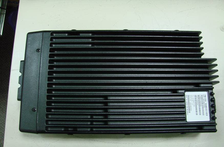
Click to zoom
Application Details
- Equipment Class
- TNB - Licensed Non-Broadcast Station Transmitter
- Date of Grant
- Sep 25, 2007
- Application Purpose
- Original Equipment
- Date of Application
- Jul 29, 2007
- Equipment Note
- Low Band Mobile 2-Way Radio
- Frequency Range
- 29.70000000 - 37.00000000
- Company
- Motorola Solutions, Inc.
- Country
- United States
Documents & Files
Document Text
Text extracted from the exhibit documents filed with the FCC. Open a document above to read the original.
Users Manual
PM1200 Control Head PM1200.book Page i Thursday, June 21, 2007 3:58 PM PM1200 Mobile Radio with Control Headi PM1200 Mobile Radio with Control Head User’s Guide 6880309U08-A *6880309U08* PM1200.book Page i Thursday, June 21, 2007 3:58 PM iii Product Safety and RF Exposure Product Safety and RF Exposure Compliance ATTENTION! This radio is restricted to occupational use only to satisfy FCC RF energy exposure requirements. Before using this product, read the RF energy awareness information and operating instructions below. Product Safety and RF Energy Exposure Booklet for Mobile Two-Way Radios Installed in Vehicles or as Fixed Site Control Stations ATTENTION! The information provided in this document supersedes the general safety information contained in user guides published prior to February 2002. RF Energy Exposure Awareness and Control Information, and Operational Instructions for FCC Occupational Use Requirements NOTICE: This radio is intended for use in occupational/controlled conditions, where users have full knowledge of their exposure and can exercise control over their exposure to meet FCC limits. This radio device is NOT authorized for general population, consumer, or any other use. This 2-way radio uses electromagnetic energy in the radio frequency (RF) spectrum to provide communications between two or more users over a distance. It uses radio frequency (RF) energy or radio waves to send and receive calls. RF energy is one form of electromagnetic energy. Other forms include, but are not limited to, sunlight and x- rays. RF energy, however, should not be confused with these other forms of electromagnetic energy, which when used improperly, can cause biological damage. Very high levels of x-rays, for example, can damage tissues and genetic material. Experts in science, engineering, medicine, health, and industry work with organizations to develop standards for safe exposure to RF energy. These standards provide recommended levels of RF exposure for both workers and the general public. These recommended RF exposure levels include substantial margins of protection. Before using this product, read the operating instructions for safe usage contained in the Product Safety and RF Exposure booklet enclosed with your radio. BEFORE USING THIS RADIO, READ THIS BOOKLET WHICH CONTAINS IMPORTANT OPERATING INSTRUCTIONS FOR SAFE USAGE AND RF ENERGY AWARENESS AND CONTROL INFORMATION FOR COMPLIANCE WITH RF ENERGY EXPOSURE LIMITS IN APPLICABLE NATIONAL AND INTERNATIONAL STANDARDS. ! C a u t i o n PM1200.book Page iii Thursday, June 21, 2007 3:58 PM PM1200 Mobile Radio with Control Headiv All Motorola 2-way radios are designed, manufactured, and tested to ensure they meet government-established RF exposure levels. In addition, manufacturers also recommend specific operating instructions to users of 2-way radios. These instructions are important because they inform users about RF energy exposure and provide simple procedures on how to control it. Please refer to the following Web sites for more information on what RF energy exposure is and how to control your exposure to assure compliance with established RF exposure limits. http://www.fcc.gov/oet/rfsafety/rf-faqs.html http://www.osha.gov/SLTC/radiofrequencyradiation/index.html Federal Communication Commission Regulations The FCC rules require manufacturers to comply with the FCC RF energy exposure limits for mobile 2-way radios before they can be marketed in the U.S. When 2-way radios are used as a consequence of employment, the FCC requires users to be fully aware of and able to control their exposure to meet occupational requirements. Exposure awareness can be facilitated by the use of a label directing users to specific user awareness information. Your Motorola 2-way radio has a RF exposure product label. Also, your Motorola user manual, or separate safety booklet, includes information and operating instructions required to control your RF exposure and to satisfy compliance requirements. Compliance with RF Exposure Standard Your Motorola two-way radio is designed and tested to comply with a number of national and international standards and guidelines (listed below) regarding human exposure to radio frequency electromagnetic energy. This radio complies with the IEEE and ICNIRP exposure limits for occupational/controlled RF exposure environment at duty factors of up to 50% talk-50% listen and is authorized by the FCC for occupational use. In terms of measuring RF energy for compliance with the FCC exposure guidelines, your radio antenna radiates measurable RF energy only while it is transmitting (during talking), not when it is receiving (listening) or in standby mode. Your Motorola two-way radio complies with the following RF energy exposure standards and guidelines: • United States Federal Communications Commission, Code of Federal Regulations; 47CFR part 2 sub-part J • American National Standards Institute (ANSI) / Institute of Electrical and Electronic Engineers (IEEE) C95. 1-1992 • Institute of Electrical and Electronic Engineers (IEEE) C95.1-2005 Edition • International Commission on Non-Ionizing Radiation Protection (ICNIRP) 1998 • Ministry of Health (Canada) Safety Code 6. Limits of Human Exposure to Radio Frequency Electromagnetic Fields in the Frequency Range from 3 kHz to 300 GHz, 1999 • Australian Communications Authority Radiocommunications (Electromagnetic Radiation - Human Exposure) Standard, 2003 • ANATEL, Brazil Regulatory Authority, Resolution 256 (April 11, 2001) “additional requirements for SMR, cellular, and PCS product certification.” PM1200.book Page iv Thursday, June 21, 2007 3:58 PM v RF Exposure Compliance and Control Guidelines and Operating Instructions To control exposure to yourself and others and to ensure compliance with the RF exposure limits, always adhere to the following procedures. Guidelines: • User awareness instructions should accompany device when transferred to other users. • Do not use this device if the …
Text truncated - open the document above for the full version.
Attestation Statements
Applicant: Motorola Inc. FCC ID: AZ492FT1629 EXHIBIT 2 SHEET 1 OF 1 EXHIBIT 2 CERTIFICATION OF DATA - Pursuant to 47 CFR 2.907 The technical data supplied with this application, having been taken under my supervision is hereby duly certified. The following is a statement of my qualifications: I received a BENG. Hons (Communication & Electronics) degree from the University Of Northumbria at Newcastle, UK. I have 7 years experience in developing, testing, and certifying Land Mobile Communications Products. NAME: Suresh Anand Krishnan SIGNATURE: /s/Suresh Anand (signed) DATE: July 23, 2007 POSITION: Electrical Engineer I hereby certify that the above application was prepared under my direction and that to the best of my knowledge and belief, the facts set forth in the application and accompanying technical data are true and correct. NAME: EH Teoh SIGNATURE: /s/ EH Teoh(signed) DATE: July 23, 2007 POSITION: Engineering Manager
Cover Letter(s)
EXHIBIT 13B SHEET 1 FCC ID: AZ492FT1629 REQUEST FOR CONFIDENTIALITY Date: July 23 rd , 2007 Authorization & Evaluation Division Federal Communications Commission Laboratory 7435 Oakland Mills Road Columbia, MD 21046 Subject: Application for Certification of Transmitter with FCC ID: AZ492FT1629 Dear Sir / Madam, Motorola is requesting that Exhibit 4 (Circuit Descriptions), Exhibit 5 (Schematic Diagrams), Exhibit 10 (Parts List and Tune-Up Procedures), and Exhibit 12 (Operational Description) not be made routinely available for public inspection. Motorola considers the information in these exhibits to be classified as trade secrets, pursuant to 47 CFR Section 0.457(d) and Section 552(b)(4) of the Freedom of Information Act. We are also requesting that the FCC mark Exhibit 3 (External Photos), Exhibit 8 and Exhibit 9 (Internal Photos) as Temporary Confidentiality as outlined in Public Notice DA 04-1705, dated June 15, 2004. This provision will give Motorola temporary confidentiality prior to product launch. Please mark Exhibits 4, 5, 10, and 12 as “Confidential” And Exhibit 3, 8 and 9 as “Temporary Confidential”. Please contact me if you require any additional information. Sincerely, /s/ Mike Ramnath (signed) Mike Ramnath Manager, Regulatory Compliance Email: [email protected]
Cover Letter(s)
EXHIBIT 13A SHEET 1 FCC ID: AZ492FT1629 Date: 23 rd July 2007 Authorization & Evaluation Division Federal Communications Commission Laboratory 7435 Oakland Mills Road Columbia, MD 21046 SUBJECT: APPLICATION FOR CERTIFICATION OF TRANSMITTER WITH FCC ID: AZ492FT1629; PM1200 LB Range 1 (29.7 – 37MHz), 50-120 Watts Rated Variable Power, Max Power 132 Watts Dear Sir / Madam, Motorola Inc., 8000 West Sunrise Blvd., Fort Lauderdale, Florida, herein submits application for Certification of the equipment identified by FCC ID number AZ492FT1629. This transmitter is primarily intended for use in a mobile radio application with capabilities for conventional communications with a conducted transmit power which is adjustable from 50.0 Watts (+46.99 dBm) to 132.0 Watts (+51.21dBm). This is a LB mobile two-way radio that operates using analog frequency modulation (FM) incorporating traditional simplex transmission protocol (50% Duty Cycle) and may be marketed to and used by employees for occupational operations, such as Federal and Public Safety agencies, e.g. police, fire and emergency medical, etc. The subject transmitter complies with CFR Title 47, Section 90.203, in that the operator cannot directly program the transmit frequencies using only the normally accessible external controls of the unit. Enclosed is a complete Certification Application. Please contact me if you require any additional information. Sincerely, /s/ Mike Ramnath (signed) Mike Ramnath Manager, Regulatory Compliance Email: [email protected]
Cover Letter(s)
24 th September 2007 Mr. Stan Lyles Authorization & Evaluation Division Federal Communications Commission Laboratory 7435 Oakland Mills Road Columbia, MD 21046 Re: Form 731 Confirmation Number: EA503194 with FCC ID: AZ492FT1629 Dear Mr. Lyles; Motorola Inc., 8000 West Sunrise Boulevard, Fort Lauderdale, Florida, herein submits its response to the 19 th September request for information in Correspondence Number 33815. Q1) This filing has requested Form-731 line-entry including frequencies at which part 90 operations are not licensable, in which case FCC requests applicants to address items per KDB pub. 634817, ie attestation letter, or split-up grant line- entries such as below and with appropriate test data, etc. - please advise and/or am! end filing accordingly. Example: 29.7-29.8 90; 29.91-30 90 (Fixed Service); 30.56- 32 90; 33-34 90 KDB pub 634817 Frequency Range Listings For Certification Grants. NOTE: entire bands eg in 90.205, 90.209, 90.210 generic listings do not denote actual allowed and licensable part 90 frequencies R1) These radios will also be marketed to the elements of the US Federal Government (NTIA), exported to Canada and other International markets. For the United States market, the radios will be programmed on authorized frequencies that are licensed by the FCC. Please contact me at (954) 723-5793 if I can be of further assistance. Sincerely, /s/ Mike Ramnath (signed) Manager, Regulatory Compliance Email: [email protected]
External Photos
Applicant: Motorola Inc. FCC ID: AZ492FT1629 EXHIBIT 3 SHEET 1 OF 3 EXHIBIT 3 EXTERNAL PHOTOGRAPHS - Pursuant to 47 CFR 2.1033(c) 12 Figure 3.1: Front View of control Head Figure 3.2: Rear View of the Control head Applicant: Motorola Inc. FCC ID: AZ492FT1629 EXHIBIT 3 SHEET 2 OF 3 Figure 3.3: Left side of Control Head Figure 3.4: Right side of Control Head Applicant: Motorola Inc. FCC ID: AZ492FT1629 EXHIBIT 3 SHEET 3 OF 3 Figure 3.5: Top view of the Control head Figure 3.12: Back view of the brick (FCC Label Location) Figure 3.13: A top view of the brick + control head + RSM (RSM must have the RF Exposure label) Figure 3.14: RF Exposure Label (close view)
ID Label/Location Info
Applicant: Motorola Inc. FCC ID: AZ492FT1629 EXHIBIT 1 SHEET 1 OF 2 EXHIBIT 1 IDENTIFICATION LABEL - Pursuant to 47 CFR 2.925(a), 2.1033(c), 2.0165 EXHIBIT 1A - LABEL LOCATION A nameplate of the type presented below will be affixed to every transmitter. It will be placed on the bottom of the unit near the front. Shown below is a photo of the actual label affixed to the cast chassis of the transmitter. EXHIBIT 1B - LABEL TYPE The label is a paper polyester film laminate with a pressure sensitive adhesive backing. The adhesive is a permanent type acrylic with minimum peel strength of 40 oz/inch. Please note that Motorola complies with FCC Rule Part 2.925 (d) that the label is permanently affixed and is readily visible to the purchaser at the time of purchase. Figure 1: FCC Label EXHIBIT 1C - GENERAL INFORMATION 1. Application References: TIA/EIA-603B Land Mobile FM or PM Communications Equipment Measurement and Performance Standards Code of Federal Regulations Title 47, Part 2, Sec. 2.1033-2.1057 and Part 90, Section 90.210. 2. Data Submittal Procedure: Data is supplied in accordance with Part 2, Sub-part J of the Commission’s rules. The intended use of this transceiver includes applications covered in the Code of Federal Regulations Title 47 and Part 90. Maximum transmitter power shall not be adjustable by the user. Applicant: Motorola Inc. FCC ID: AZ492FT1629 EXHIBIT 1 SHEET 2 OF 2 3. Applicable Reference • Reference Certification FCC ID: AZ492FT1629 • EIA/TIA-603 Land Mobile FM or PM Communications Equipment Measurement and Performance Standards. • FCC Rule Part 2 Sec. 2.1033-2.1057 • FCC Rule Part 90 Sec.90.210
Internal Photos
Applicant: Motorola Inc. FCC ID: AZ492FT1629 EXHIBIT 9 SHEET 1 OF 5 EXHIBIT 9 INTERNAL PHOTOGRAPHS - Pursuant to 47 CFR 2.1033(c) 12 Figure 9.1: RF amplifier unit front view Figure 9.2 : RF controller unit front view (with shield) Applicant: Motorola Inc. FCC ID: AZ492FT1629 EXHIBIT 9 SHEET 2 OF 5 Figure 9.3 : RF controller unit front view (without shield) Figure 9.4 : RF controller unit back view Applicant: Motorola Inc. FCC ID: AZ492FT1629 EXHIBIT 9 SHEET 3 OF 5 Figure 9.5 : Interface front view (1) Figure 9.6 : Interface front view (2) Applicant: Motorola Inc. FCC ID: AZ492FT1629 EXHIBIT 9 SHEET 4 OF 5 Figure 9.7: Interface back view (1) Figure 9.8: Interface back view (2) Applicant: Motorola Inc. FCC ID: AZ492FT1629 EXHIBIT 9 SHEET 5 OF 5 Figure 9.9: LCD display front view
RF Exposure Info
FCC ID: AZ492FT1629 SR5222 Form-MPE Vehicle rpt. Rev 3.00 Page 1 of 24 TESTING CERT #2518.01 FCC ID: AZ492FT1629 DECLARATION OF COMPLIANCE MPE ASSESSMENT Networks & Enterprise EME Test Laboratory 8000 West Sunrise Blvd Fort Lauderdale, FL. 33322 Date of Report: 7/16/07 Report Revision: Rev. O Report ID: MPE rpt_PM1200_ 29-37MHz _ Rev O_070716_SR5222 Responsible Engineer: Stephen C. Whalen (Principle Staff EME Eng.) Date/s Tested: 7/9/07 - 7/10/07 Manufacturer/Location: Vertex, Japan Date submitted for test: 7/3/07 DUT Description: PM1200 29.7-37.0MHz 120W Test TX mode(s): CW Max. Power output: 132W, 50% Duty Cycle (PTT) TX Frequency Bands: 29.7-37.0 MHz Signaling type: FM Model(s) Tested: AAM32BMD9PW5AN Model(s) Certified: AAM32BMD9PW5AN Serial Number(s): 1591HE0010 Classification: Occupational Controlled (Operator); General Population/Uncontrolled (Passengers/Bystanders) Rule Part(s): 2.1091 (d) Approved Accessories: Antenna(s): RAB4002ARB (29.7-36.0MHz ¼ Wave 0dBd) RAB4003ARB (36-42MHz ¼ Wave 0dBd) Final RF Exposure Results: Mobile Max Calculated Magnetic Field Strength = 0.069A/m Based on the information and the testing results provided herein, the undersigned certifies that when used as stated in the operating instructions supplied, said product complies with the national and international reference standards and guidelines listed in section 3.0 of this report. This report shall not be reproduced without written approval from an officially designated representative of the Motorola EME Laboratory. Signature on file Deanna Zakharia – N&E EME Lab Senior Resource Manager, Laboratory Director, Approval Date: 7/16/2007 Certification Date: 7/16/2007 Certification No.: L1070708 FCC ID: AZ492FT1629 SR5222 Form-MPE Vehicle rpt. Rev 3.00 Page 2 of 24 TABLE OF CONTENTS 1.0 Product and System Description 2.0 Additional Options and Accessories 3.0 Measurement and Limit Standards 4.0 Data Collection Consideration 5.0 Measurement System Uncertainty Levels 6.0 Method of Measurement 6.1 EME measurements made with trunk mounted antenna 6.1.1 External vehicle EME measurements 6.1.2 Internal vehicle EME measurement 7.0 Test Site 8.0 Measurement System/Equipment 9.0 Test Unit Description 10.0 Test Set-Up Description 11.0 Test Results Summary 12.0 Conclusion APPENDIX A: Illustration of Antenna Location and Test Distances APPENDIX B: Meter/Probe Calibration Certificates APPENDIX C: Photos of Assessed Antennas APPENDIX D: Detailed MPE Measurement Data REVISION HISTORY Date Revision Comments 7/16/07 O Initial release FCC ID: AZ492FT1629 SR5222 Form-MPE Vehicle rpt. Rev 3.00 Page 3 of 24 1.0 Product and System Description FCC ID: AZ492FT1629, model AAM32BMD9PW5AN is a mobile transceiver that utilizes frequency modulation (FM) half duplex transmission technology. The modulation could be conventional analog voice, tone PL and DPL. This device uses the external 1/4λ antennas that are capable of transmitting within their respective ranges in the 29.7-37.0MHz bands and with transmit powers up to 132 watts maximum. The intended use of the radio is Push-To-Talk (PTT) while the device is properly installed in a vehicle with an external antenna mounted at the center of the trunk. This device will be marketed to and used by employees solely for work-related operations, such as public safety agencies, e.g. police, fire and emergency medical. User training is the responsibility of these agencies which can be expected to employ the usage instructions, safety information and operational cautions set forth in the user's manual, instructional sessions or other means. Accordingly this product is classified as Occupational/Controlled Exposure. However, In accordance with FCC requirements, the passengers inside the vehicle and the bystanders external to the vehicle are evaluated to the General Population/Uncontrolled Exposure Limits. (Note that “By-standers” as used herein mean people other than operator) 2.0 Additional Options and Accessories: NA 3.0 Measurement and Limit Standards Measurements were performed according to the recommended guidelines in IEEE/ANSI C95.3- 2002 and compared to FCC Limits Per 47 CFR 2.1091 (d) for General Population/Uncontrolled RF Exposure. For test frequencies ranging from 29.7-37.0 MHz the MPE (Maximum Permissible Exposure) limit to electromagnetic energy in equivalent plane wave free-space power density is 0.2mW/cm 2 , and 0.073 – 0.074A/m for the magnetic field strength. 4.0 Data Collection Consideration Power density testing was performed with DUT installed in a 1991 Ford Taurus (4-door). Measurement data was taken with the vehicles’ electrical system powered by an equivalent source equal to the car running at idle and the vehicle battery measuring 13.8 volts. FCC ID: AZ492FT1629 SR5222 Form-MPE Vehicle rpt. Rev 3.00 Page 4 of 24 5.0 Measurement System Uncertainty Levels The information below presents an estimate of the possible errors that are associated with the measurement system. Uncertainty Budget for Near Field Probe Measurements Tol. Prob . u i (± %) Dist. Divisor (±%) Measurement System Survey Meter Calibration 3.0 N 1.00 3.0 Repeatability Accuracy 7.0 N 1.00 7.0 Combined Standard Uncertainty RSS 7.6 Expanded Uncertainty k=2 15 6.0 Method of Measurement 6.1 EME measurements made with trunk mounted antenna(s) (For reference, see Illustration of antenna location and test distances in appendix A) 6.1.1 External vehicle EME measurement (Antenna mounted at trunk center) MPE measurements for by-stander conditions are determined by taking the average of (10) measurements in a 2m vertical line for each of the (3) test locations indicated in appendix A with 20cm increments at the test distance of 150cm from the vehicle’s body, as stated in the user manual. The measurement probe sensor is rotated 180º at each of the ten incremental measurements to ensure the highest result is captured. These measurements are representative of persons other than the operator standing next to the vehicle. The offer…
Text truncated - open the document above for the full version.
RF Exposure Info
14 th September 2007 Mr. Stan Lyles Authorization & Evaluation Division Federal Communications Commission Laboratory 7435 Oakland Mills Road Columbia, MD 21046 Re: Form 731 Confirmation Number: EA503194 with FCC ID: AZ492FT1629 Dear Mr. Lyles; Motorola Inc., 8000 West Sunrise Boulevard, Fort Lauderdale, Florida, herein submits its response to the 10 th September request for information in Correspondence Number 33729. Q1) User manual, op desc etc mention antenna options for 37-50 MHz, different from frequency range requested for this filing - please explain and/or revise R1) The user manual is used for more than one radio. The antennas applicable for this filing were tested while those antennas that doe not match this filing’s frequency range were not tested for this application. Q2) If not in filing already, please submit specs / spec-sheets for antennas R2) The antenna specs (freq. range, electrical length and gain) are listed on the front cover of the report. Additional antenna information is as follows; Antenna Test Freq. Physical Length RAB4002ARB 29.7MHz 135.2cm RAB4002ARB 32.0MHz 116.0cm RAB4002ARB 35.1MHz 96.0cm RAB4003ARB 36.5MHz 126.0cm Q3) MPE report mentions 0.074 A/m as a limit, which appears to be incorrect - please explain and/or revise where appropriate R3) Section 3.0 lists the A/m MPE limits for frequency range 29.7-37.0MHz. These limits were derived from OET Bulletin 65 as follows; Frequency range 1.34-30MHz use 2.19/freq(MHz) => 2.19/29.7MHz = 0.0737A/m Frequency range 30-300MHz use 0.073A/m Therefore the MPE limit range used for frequencies 29.7-37.0MHz is 0.073-0.074A/m Q4) MPE report at several places appears to indicate that measurements were done using only an H-field probe and with a plane-wave-equivalent power density assumption to convert to E-field, which conversion is generally applicable and allowed for far-field plane-wave situations only. For the near-field conditions herein, please revise MPE report to include actual results tested using both E-field and H- field probes. R)4 Both E and H fields were measured separately and are presented in summary tables 1 & 2 on page 7 and in appendix D Detailed MPE Data (tables 1-10, E field and tables 11-20, H field). Q5) MPE report mentions E-field probe model 8722B and includes corresponding calib. certificate, however other parts of report appear to indicate that only H-field tests were done, such that E-field probe appears not applicable - please explain and/or revise where appropriate R5) E-field data is presented in summary table 1 on pg 7 and in appendix D (tables 1-10). Q6) MPE probe calib. certs show client "Lockheed Martin" - please explain whether correct certs were provided and used for this Motorola lab test, or revise filing if appropriate R6) Motorola’s outsourced calibration lab uses Lockheed Martin as an alternate calibration source. Lockheed Martin submitted the equipment to Liberty Labs for Calibration. The calibration sheets are correct. Q7) MPE report at 6.1.1 has the following two apparently inconsistent statements, and which may not be consistent with Appdx A - please explain and/or revise where appropriate: "at the test distance of 150cm from the vehicle's body" "at the rear of the vehicle while maintaining a twenty (20) centimeter separation distance between the probe sensor and vehicle body" R7) The 150cm test distance is the distance from the vehicle’s body to the bystander. The 20cm distance stated ensures that the probe sensor and vehicle body are not closer than 20cm as recommended in IEEE C95.3 2002. This 20cm separation distance is to improve measurement accuracy. Obviously for this filing the 150cm distance would imply that the 20cm distance was met. This section of the report template is under review for improved clarification. Q8) User manual mentions roof-mount antenna, however MPE report appears to include only trunk-mount data - please explain and/or revise where appropriate R8) The user manual states the following; “Antennas should be installed in the center area of the roof or trunk lid taking into account exposure conditions of the backseat passengers and according to the specific instructions and restrictions in the Radio Installation Manual along with the requirements of the antenna supplier.” The Radio Installation Manual, section 2.4.1, clearly states the mounting restrictions for this radio model is in the center of the trunk. Q9) MPE report Appdx D includes "Highest Reading" for some "Meas. Distance" - if not in filing already, please explain applicable range of distances and as relative to Appdx A figure R9) The tables to which you refer to are for passengers inside the automobile, front seat and backseat. The closest distance from the antenna to the passenger (head) in the back seat is 85cm, which is illustrated in appendix A. The distance to the passenger in the center of front seat (head) is 148cm. The front seat distance was not provided in appendix A. Appendix A of the report template is under review for improved clarification. Q10) Further to preceding question, please explain and/or show in a revised Appdx A figure the 40 cm by ?? cm plane (or typical planes) used to represent passenger exposures R10) As stated in 6.2.2; after the highest level is found at the head area, two additional areas (chest and trunk) were scanned vertically below the head area and 40cm wide. The diagram below is being considered for future filings. Please contact me at (954) 723-5793 if I can be of further assistance. Sincerely, /s/ Mike Ramnath (signed) Manager, Regulatory Compliance Email: [email protected]
Test Report
Applicant: Motorola Inc. FCC ID: AZ492FT1629 EXHIBIT 6 SHEET 1 OF 16 EXHIBIT 6 INDEX OF SUBMITTED MEASURED DATA This exhibit contains the measured data for this equipment as follows: EXHIBIT 6A – RF Power Output (Table) EXHIBIT 6B – Audio Frequency Response (1 Graph) Figure 6B-1: 20 kHz Channel Spacing EXHIBIT 6C – Audio Low Pass Filter Response (1Graph) Figure 6C-1: 20 kHz Channel Spacing EXHIBIT 6D – Modulation Limiting (2Graphs) Figure 6D-1: 20 kHz Channel Spacing, Positive Peak, Carrier Squelch (CSQ) Mode Figure 6D-2: 20 kHz Channel Spacing, Negative Peak, Carrier Squelch (CSQ) Mode EXHIBIT 6E- Occupied Bandwidth Data (12 Spectrum Analyzer Plots) Figure 6E-1: 20 kHz Channel Spacing, High Power, 29.7 MHz, 16K0F3E Figure 6E-2: 20 kHz Channel Spacing, High Power, 29.7 MHz, 16K0F3E Figure 6E-3: 20 kHz Channel Spacing, High Power, 33.35 MHz, 16K0F3E Figure 6E-4: 20 kHz Channel Spacing, High Power, 33.35 MHz, 16K0F3E Figure 6E-5: 20 kHz Channel Spacing, High Power, 37 MHz, 16K0FE Figure 6E-6: 20 kHz Channel Spacing, High Power, 37 MHz, 16K0F3E Figure 6E-7: 20 kHz Channel Spacing, Low Power, 29.7 MHz, 16K0F3E Figure 6E-8: 20 kHz Channel Spacing, Low Power, 29.7 MHz, 16K0F3E Figure 6E-9: 20 kHz Channel Spacing, Low Power, 33.35 MHz, 16K0F3E Figure 6E-10: 20 kHz Channel Spacing, Low Power, 33.35 MHz, 16K0F3E Figure 6E-11: 20 kHz Channel Spacing, Low Power, 37 MHz, 16K0F3E Figure 6E-12: 20 kHz Channel Spacing, Low Power, 37 MHz, 16K0F3E EXHIBIT 6F – Conducted Spurious Emissions (6 Graphs) Figure 6F-1: High Power, 29.725 MHz, 20 kHz Channel Spacing Figure 6F-2: High Power, 33.400 MHz, 20 kHz Channel Spacing Figure 6F-3: High Power, 36.975 MHz, 20 kHz Channel Spacing Figure 6F-4: Low Power, 29.725 MHz, 20 kHz Channel Spacing Figure 6F-5: Low Power, 33.400 MHz, 20 kHz Channel Spacing Figure 6F-6: Low Power, 36.975 MHz, 20 kHz Channel Spacing EXHIBIT 6G – Radiated Spurious Emissions (6 Graphs) Figure 6G-1: High Power, 29.725 MHz, 20 kHz Channel Spacing Figure 6G-2: High Power, 3.400 MHz, 20 kHz Channel Spacing Figure 6G-3: High Power, 36.975 MHz, 20 kHz Channel Spacing Figure 6G-4: Low Power, 29.725 MHz, 20 kHz Channel Spacing Figure 6G-5: Low Power, 33.400 MHz, 20 kHz Channel Spacing Figure 6G-6: Low Power, 36.975 MHz, 20 kHz Channel Spacing EXHIBIT 6H – Frequency StabilitySupply Voltage (2 Graphs) Figure 6H-1: Frequency Stability vs. Temperature, 33.35 MHz Figure 6H-2: Frequency Stability vs. Percentage of Supply Voltage Change, 33.35 MHz EXHIBIT 6A – RF Conducted Power Output Data – Pursuant 47 CFR 2.1046(a), 2.1033(c)(6), 2.1033(c)(7) Applicant: Motorola Inc. FCC ID: AZ492FT1629 EXHIBIT 6 SHEET 2 OF 16 and 2.1033(c)(8) The RF power output was measured with the indicated voltage applied to and current into the final RF amplifying device. At High Power setting, Low Frequency 29.7 MHz: Output RF power 132 Watts DC Voltage 13.4 Volts DC Current 17.5 Amps At Nominal Power setting, Low Frequency 29.7 MHz: Output RF power 118.2 Watts DC Voltage 13.4 Volts DC Current 16.8 Amps At Low Power setting, Low Frequency 29.7 MHz: Output RF power 49.27Watts DC Voltage 13.4 Volts DC Current 12.5 Amps At High power setting, Medium Frequency 33.35 MHz: Output RF power 131.9 Watts DC Voltage 13.4 Volts DC Current 17.09 Amps At Nominal Power setting, Medium Frequency 33.35 MHz: Output RF power 119.4 Watts DC Voltage 13.4 Volts DC Current 16.5 Amps At Low output power setting, Medium Frequency 33.35 MHz: Output RF power 48.010 Watts DC Voltage 13.6 Volts DC Current 12.72Amps At High power setting, High Frequency 37 MHz: Output RF power 132 Watts DC Voltage 13.4 Volts DC Current 17.48 Amps At Nominal Power setting, High Frequency 37 MHz: Output RF power 118.6 Watts DC Voltage 13.4 Volts DC Current 16.3 Amps At Low power setting, High Frequency 37 MHz: Output RF power 49.27 Watts DC Voltage 13.4 Volts DC Current 12.4 Amps Applicant: Motorola Inc. FCC ID: AZ492FT1629 EXHIBIT 6 SHEET 3 OF 16 EXHIBIT 6B – Transmit Audio Response – Pursuant 47 CFR 2.1047 and 2.1033(c) (13) -20 -16 -12 -8 -4 0 4 8 12 16 20 …
Text truncated - open the document above for the full version.
Contact Information
Applicant
Arine Lee(Certification Manager)
Technical Contact
MotorolaMike Ramnath
[email protected]954-723-5793
8000 West Sunrise Blvd · Ft. Lauderdale, Florida · United States
Technical Specifications
| # | Rule Parts | Frequency Range | Power Output | Emission | Tolerance |
|---|---|---|---|---|---|
| 1 | 90 | 29.7 MHz - 37 MHz | 120 W | 16K0F3E | 10.0000000000 ppm |
Other Applications from Motorola Solutions, Inc.

AZ489FT4980
Sep 08, 2026Portable two way radio
Equipment Class
TNF - Licensed Non-Broadcast Transmitter Held to FaceAZ489FT4981
Aug 14, 2026Handheld Portable - TANAPA BPR 45 400-470 MHZ 4W NKP
Equipment Class
TNF - Licensed Non-Broadcast Transmitter Held to Face
AZ489FT7187
Jul 13, 2026Portable 2-Way Radio with Bluetooth, Bluetooth LE, WIFI 2.4GHz, WIFI 5GHz, LTE
Equipment Class
DSS - Part 15 Spread Spectrum TransmitterAZ499FT6031
May 11, 2026Operation Critical Wireless Earpiece PTT
Equipment Class
DSS - Part 15 Spread Spectrum Transmitter
AZ499FT5879
Dec 19, 20252-way Portable Radio with BT, BTLE, WIFI, NFC and LTE
Equipment Class
DSS - Part 15 Spread Spectrum Transmitter