AZ492FT4859Mobile and Base Station Transmitter
Motorola Solutions, Inc.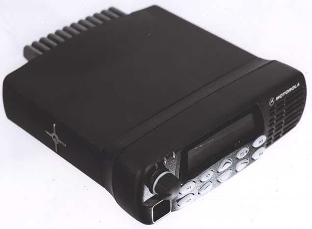
Click to zoom
Application Details
- Equipment Class
- TNB - Licensed Non-Broadcast Station Transmitter
- Date of Grant
- Dec 10, 2002
- Application Purpose
- Original Equipment
- Date of Application
- Dec 10, 2002
- Equipment Note
- Mobile and Base Station Transmitter
- Frequency Range
- 450.00000000 - 512.00000000
- Company
- Motorola Solutions, Inc.
- Country
- United States
Documents & Files
Document Text
Text extracted from the exhibit documents filed with the FCC. Open a document above to read the original.
Users Manual
i English CONTENTS CONTENTS Computer Software Copyrights . . . . . . . . . . . .iiSafety . . . . . . . . . . . . . . . . . . . . . . . . . . . . . . 1Product Safety and RF Exposure Compliance . . . . . . . . . . . . . . . . . . . . . . . . . 1 Radio Overview . . . . . . . . . . . . . . . . . . . . . . 3Parts of the Radio . . . . . . . . . . . . . . . . . . . . . 3 Optional Enhanced Keypad Microphone (RMN4026) . . . . . . . . . . . . . . . . . . . . . . . 4 On/Off/Volume Knob . . . . . . . . . . . . . . . . 5Channel Selector Buttons . . . . . . . . . . . . 5LED Indicators . . . . . . . . . . . . . . . . . . . . . 5Programmable Buttons . . . . . . . . . . . . . . 5Push-to-Talk (PTT) Button . . . . . . . . . . . . 8Microphone . . . . . . . . . . . . . . . . . . . . . . . 8Use with Enhanced Keypad Microphone (RMN4026) . . . . . . . . . . . . . . . . . . . . . . . 8 LCD Screen . . . . . . . . . . . . . . . . . . . . . . . 8 Audio Indicators for Programmable Buttons 10Getting Started . . . . . . . . . . . . . . . . . . . . . 11Turning the Radio On or Off . . . . . . . . . . . . 11Adjusting the Volume . . . . . . . . . . . . . . . . . 11Selecting a Zone . . . . . . . . . . . . . . . . . . . . . 12Selecting a Radio Channel . . . . . . . . . . . . . 12 Sending a Call . . . . . . . . . . . . . . . . . . . . . . . 13Receiving a Call . . . . . . . . . . . . . . . . . . . . . . 13Radio Calls . . . . . . . . . . . . . . . . . . . . . . . . . 15Making a Selective Call . . . . . . . . . . . . . . . . 15Receiving a Selective Call F . . . . . . . . . . . . . 16Sending a Call Alert™ Page . . . . . . . . . . . . . 16Receiving a Call Alert Page . . . . . . . . . . . . . 17Radio Check . . . . . . . . . . . . . . . . . . . . . . . . . 19responding to emergency alerts E . . . . . . . . . . . . . . . . . . . . . . . . . . . . 21 Decoding an Emergency Alarm . . . . . . . .21Multiple Queued Emergencies . . . . . . . . 22Three Minute Timer . . . . . . . . . . . . . . . . . 22After the Timer Expires . . . . . . . . . . . . . .22 Clearing an Emergency Alert E . . . . . . . . . . . . . . . . . . . . . . . . . . . . . 23 Sending an Emergency Remote Monitor . . . 23Sending an Emergency Alert E . . . . . . . . . . 24Selective Radio Inhibit . . . . . . . . . . . . . . . . . 24Repeater or Talkaround J Mode . . . . . . . . . 24Setting the Power Level B . . . . . . . . . . . . . . 25Name and Call Tone Tagging. . . . . . . . . . . . 26Scan . . . . . . . . . . . . . . . . . . . . . . . . . . . . . . . 29Starting or Stopping Scan G . . . . . . . . . . . . . 29Talkback . . . . . . . . . . . . . . . . . . . . . . . . . . . . 30Deleting a Nuisance Channel . . . . . . . . . . . . 30 ii English CONTENTS Restoring a Channel to the Scan List . . . 30 Editing a Scan List . . . . . . . . . . . . . . . . . . . . 30 Adding or Deleting Channels in a Scan List 31 Prioritizing a Channel in a Scan List . . . . 32Setting Priority Channels . . . . . . . . . . . . . 32 Phone. . . . . . . . . . . . . . . . . . . . . . . . . . . . . . 35Making a Phone Call D . . . . . . . . . . . . . . . . . 35Audio/Tone Settings. . . . . . . . . . . . . . . . . .37Utilities. . . . . . . . . . . . . . . . . . . . . . . . . . . . . 39Selecting the Display Language . . . . . . . . . . 40Warranty . . . . . . . . . . . . . . . . . . . . . . . . . . . 41Limited Warranty. . . . . . . . . . . . . . . . . . . . . . 41Accessories . . . . . . . . . . . . . . . . . . . . . . . . 45Audio . . . . . . . . . . . . . . . . . . . . . . . . . . . . . . 45Mounting . . . . . . . . . . . . . . . . . . . . . . . . . . . .45Antennas . . . . . . . . . . . . . . . . . . . . . . . . . . . 46Control Station . . . . . . . . . . . . . . . . . . . . . . . 46 COMPUTER SOFTWARE COPYRIGHTSThe Motorola products described in this manual may include copyrighted Motorola computer programs stored in semiconductor memories or other media. Laws in the United States and other countries preserve for Motorola certain exclusive rights for copyrighted computer programs including, but not limited to, the exclusive right to copy or reproduce in any form the copyrighted computer program. Accordingly, any copyrighted Motorola computer programs contained in the Motorola products described in this manual may not be copied, reproduced, modified, reverse-engineered, or distributed in any manner without the express written permission of Motorola. Furthermore, the purchase of Motorola products shall not be deemed to grant either directly or by implication, estoppel, or otherwise, any license under the copyrights, patents or patent applications of Motorola, except for the normal non-exclusive license to use that arises by operation of law in the sale of a product. 1 English SAFETY SAFETY PRODUCT SAFETY AND RF EXPOSURE COMPLIANCE ATTENTION! This radio is restricted to occupational use only to satisfy FCC RF energy exposure requirements. Before using this product, read the RF energy awareness information and operating instructions in the Product Safety and RF Exposure booklet enclosed with your radio to ensure compliance with RF energy exposure limits.For a list of Motorola-approved antennas, batteries, and other accessories, visit the following web site which lists approved accessories: http://www.motorola.com/cgiss/ index.shtml . Before using this product, read the operating instructions for safe usage contained in the Product Safety and RF Exposure booklet enclosed with your radio. ! C a u t i o n 2 English SAFETY Notes 3 English RADIO OVERVIEW RADIO OVERVIEW PARTS OF THE RADIO MAEPF-26782-O (Interchangeable) Programmable Button 2 (P2) (Interchangeable) Programmable Button 4 (P4) (Interchangeable) Programmable Button 3 (P3) Red/Yellow/GreenLED Indicators (Interchangeable) Programmable Button 1 (P1) Microphone Ehpx Knob On/Off/Volume Channel Selector(Up/Down) LCD Screen 4 English RADIO OVERVIEW Optional Enhanced Keypad Microphone (RMN4026)Your radio may be ordered with an optional DTMF (Dual-Tone Multi-Frequency) micro…
Text truncated - open the document above for the full version.
Users Manual
English Product Safety and RF Exposure for Mobile Two-Way Radios Installed in Vehicles or as Fixed Site Control Stations (CDM Professional Seriesô CDM750 / CDM1250 / CDM1550 UHF Band 2 [450-512 MHz] 1.5ppm Models) The information provided in this document supersedes the general safety information contained in user guides published prior to February 2002. Compliance with RF Energy Exposure Standards NOTICE: This radio is intended for use in occupational/controlled applications where users have been made aware of the potential for exposure and can exercise control over their exposure. This radio device is NOT authorized for general population, consumer or similar use. BEFORE USING THIS RADIO, READ THIS BOOKLET WHICH CONTAINS IMPORTANT OPERATING INSTRUCTIONS FOR SAFE USAGE AND RF ENERGY AWARENESS AND CONTROL INFORMATION FOR COMPLIANCE WITH RF ENERGY EXPOSURE LIMITS IN APPLICABLE NATIONAL AND INTERNATIONAL STANDARDS. ! C a u t i o n © Motorola, Inc. 2002 8000 W. Sunrise Blvd., Ft. Lauderdale, FL 33322 Printed in U.S.A. 7/02. *6881096C69* 68P81096C69-O 2 English Federal Communication Commission Regulations The FCC has established limits for safe exposure to radio frequency (RF) emissions from mobile two-way radios. The FCC requires manufacturers to demonstrate compliance with RF exposure limits before mobile two-way radios can be marketed in the U.S. When two-way radios are approved for occupational/controlled environment exposure limits, the FCC requires users to be fully aware of, and exercise control over, their exposure. Awareness and control of RF exposure can be accomplished by education or training through appropriate means such as information and instructions in user manuals or safety booklets, or other appropriate means. This user safety booklet includes useful information about RF exposure and helpful instructions on how to control your RF exposure. Your Motorola two-way radio is designed and tested to comply with a number of national and international standards and guidelines (listed below) regarding human exposure to radio frequency electromagnetic energy. This radio complies with the IEEE (FCC) and ICNIRP exposure limits for occupational/controlled RF exposure environments at usage factors of up to 50% talkñ50% listen. In terms of measuring RF energy for compliance with FCC exposure guidelines, your radio radiates measurable RF energy only while it is transmitting (during talking), not when it is receiving (listening) or in standby mode. 3 English Your Motorola two-way radio complies with the following RF energy exposure standards and guidelines: ï United States Federal Communications Commission, Code of Federal Regulations; 47CFR part 2 sub-part J ï American National Standards Institute (ANSI) / Institute of Electrical and Electronic Engineers (IEEE) C95. 1-1992 ï Institute of Electrical and Electronic Engineers (IEEE) C95.1-1999 Edition ï International Commission on Non-Ionizing Radiation Protection (ICNIRP) 1998 ï Ministry of Health (Canada) Safety Code 6. Limits of Human Exposure to Radiofrequency Electromagnetic Fields in the Frequency Range from 3 kHz to 300 GHz, 1999 ï Australian Communications Authority Radiocommunications (Electromagnetic Radiation - Human Exposure) Standard, 2001 ï ANATEL, Brasil Regulatory Authority, Resolution 256 (April 11, 2001) ìadditional requirements for SMR, cellular and PCS product certification.î 4 English Compliance and Control Guidelines and Operating Instructions for Mobile Two-Way Radios Installed in Vehicles To control your exposure and ensure compliance with the occupational/ controlled environment exposure limits, always adhere to the following procedures: ïTo transmit (talk), push the Push-To-Talk (PTT) button; to receive, release the PTT button. Transmit only when people outside the vehicle are at least the minimum lateral distance away (as shown in the table below) from a properly installed, externally-mounted antenna. The table below lists the minimum lateral distance for bystanders in an uncontrolled environment from the transmitting antenna at several different ranges of rated radio power for mobile radios installed in a vehicle. ï Install mobile antennas at the center of the roof or the center of the trunk deck. These mobile antenna installation guidelines are limited to metal body vehicles. The antenna installation must additionally be in accordance with: - The requirements of the antenna manufacturer/supplier - Instructions in the Radio Installation Manual Rated Power of Vehicle-Installed Mobile Two-way Radio Minimum Lateral Distance from Transmitting Antenna 25 to 48 watts2.5 feet (76 centimeters) 5 English Use only the Motorola-approved, supplied antenna or a Motorola- approved replacement antenna. Use of nonñMotorola-approved antennas, modifications, or attachments could damage the radio and may violate FCC regulations. ï For a list of Motorola-approved antennas, visit the following web site: http://www.motorola.com/cgiss/index.shtml . For additional information on exposure requirements or other training information, visit http://www.motorola.com/rfhealth . Compliance and Control Guidelines and Operating Instructions for Mobile Two-Way Radios Installed as Fixed Site Control Stations If mobile radio equipment is installed at a fixed location and operated as a control station or as a fixed unit, the antenna installation must comply with the following requirements in order to ensure optimal performance and compliance with the RF energy exposure limits in the standards and guidelines listed on page 3: ï The antenna should be mounted outside the building on the roof or a tower if at all possible. ï As with all fixed site antenna installations, it is the responsibility of the licensee to manage the site in accordance with applicable regulatory requirements and may require additional compliance actions such as site survey measurements, signage, and site access restrictions in order to ensure that exposure limits are not exceeded. 6…
Text truncated - open the document above for the full version.
Attestation Statements
MOTOROLA INC. FCC ID: AZ492FT4859 EXHIBIT 2 1 of 1 CERTIFICATION OF DATA STATEMENT OF CERTIFICATION The technical data supplied with this application, having been taken under my supervision is hereby duly certified. The following is a statement of my qualifications: I have received a B Eng. in Computer and Communication degree from University of Science, Penang, Malaysia in 1994. I have more than 7 years of Product Development experience in the field of two-way radio communication. NAME: Samsun Zaini SIGNATURE: Samsun Zaini DATE: 26 th November 2002 POSITION: Engineering Group Leader I hereby certify that the above application was prepared under my direction and that to the best of my knowledge and belief, the facts set forth in the application and accompanying technical data are true and correct: NAME: Azanor Muhammad SIGNATURE: Azanor Muhammad DATE: 26 th November 2002 POSITION: Engineering Section Manager
Cover Letter(s)
______________________________________________________________________________ 8000 West Sunrise Boulevard, Fort Lauderdale, Florida 33322. Confidentiality Request Date: 6 th December 2002 Authorization & Evaluation Division Federal Communications Commission Laboratory 7435 Oakland Mills Road Columbia, MD 21046 Subject: Application for Certification of Transmitter with FCC ID: AZ492FT4859. Dear Sir or Madam: Motorola is requesting that Exhibit 4 (Circuit Descriptions), Exhibit 5 (Schematic Diagrams), Exhibit 10 (Parts List and Tune Up Procedures), and Exhibit 12 (Operational Description) not be made routinely available for public inspection. Motorola considers the information in these exhibits to be classified as trade secrets, pursuant to 47 CFR Section 0.457(d) and Section 552(b)(4) of the Freedom of Information Act. Please mark Exhibits 4, 5, 10, and 12 as “Confidential.” Please contact me if you require any additional information. Sincerely, /s/ Mike Ramnath FCC Liaison Tel: (954) 723-5793 E-mail: [email protected] EXHIBIT 13b
Cover Letter(s)
January 15, 2003 6864110R19 ”6864110R19” Antenna Installation Instructions Addendum For CDM Professional Series Mobile CDM750 / CDM1250 / CDM1550 TM UHF Band 2 (450-512 MHz) 1.5 PPM Models The following chart must be used when installing an antenna to a vehicle using a 1.5 PPM CDM Professional Series Mobile. The listed installation locations have been authorized and approved by Motorola for use with the 1.5 PPM CDM Professional Series Models Do not install an antenna listed for roof mount in any location other than the roof of a vehicle. Follow all other installation directions as supplied by the antenna manufacturer/supplier. Mounting Position Antenna Model Antenna Description Roof Mount Trunk Mount Roof or Trunk Mount HAE4003 UHF 450-470 MHz, ¼ Wave Roof Mount X HAE4004 UHF 470-512 MHz, ¼ Wave Roof Mount X HAE4011 UHF 450-470 MHz, 3.5dB Gain Roof Mount X X X HAE4012 UHF 470-494 MHz, 3.5dB Gain Roof Mount X X X HAE4013 UHF 494-512 MHz, 3.5dB Gain Roof Mount X HAE4019 UHF 450-470 MHz, 5.0dB Gain Roof Mount X X X
Cover Letter(s)
FCC ID: AZ492FT4859 15 th January 2003 Mr. Tim Harrington Authorization & Evaluation Division Federal Communications Commission Laboratory 7435 Oakland Mills Road Columbia, MD 21046 TCB Audit: TC129243 with FCC ID: AZ492FT4859. Dear Mr. Harrington; Motorola Inc., 8000 West Sunrise Boulevard, Fort Lauderdale, Florida 33322, herein submits its response to the 10 h January 2003 for information in Correspondence Number TC129243. Q1) Nominal output power is 40W. 90.205(o) allows Form 731 line item power to be exceeded by 20% = 48W. Please revise Form 731 power to 40W. Grant note could be included about 90.205(o) and max power. Grant note could be included about max power in MPE test 47.1W. R1) Motorola would prefer that a maximum power of 48 Watt, as measured in Exhibit 6-A, be listed on the Grant. Q2) MPE report sec. 11 - why the factor of 2 divisor for veh. internal and external power density? If this is user-based 50% duty factor, add grant note referring to that. R2) Maximum duty cycle is 50%. Q3) MPE report sec. 11 - what are veh. spec. limits for? R3) See amended MPE Report. Q4) MPE report sec. 6 - what is distance from veh. to MPE vert. line? R4) See amended MPE Report. Q5) MPE report pp. 12-17 - FCC guidelines do not define how obtain "S.A.R. calculated." Were these numbers used in TCB compliance evaluation? Please explain, and revise report if needed. R5) MPE Report was amended to identify which antennas are to be installed on the trunk lid of a vehicle. Also, see the attached Antenna Installation Instructions Addendum Q6) In future filings, please use table-numbering and list-of-tables for MPE results to allow easier referencing. R6) See amended MPE Report for table numbering. Q7) May need grant note similar too: Output power is conducted. RF exposure compliance was determined using a x dBi, y dBi, z dBi vehicle-mount antennas only. Qualified end-users of this device must have the knowledge to control the exposure conditions of vehicle passengers, and of bystanders to ensure a minimum FCC ID: AZ492FT4859 separation distance of xx cm is maintained between the antenna and persons outside of the vehicle for satisfying MPE compliance. The antenna(s) used for this transmitter must be installed to provide a separation distance of at least xx cm from all persons and must not be co-located or operating in conjunction with any other antenna or transmitter. This device must be used with a maximum transmitting duty factor not exceeding 50% for satisfying RF exposure compliance. The operation of this transmitter must satisfy the requirements of Occupational/Controlled Exposure Environment, for work related use only. End-users must be provided with specific training instructions for meeting Occupational/Controlled Exposure Environment requirements. R7) We concur with the Grant notes. Contact me at (954) 723-5793 if you require any additional information. Regards, /s/ Mike Ramnath FCC Liaison Email: [email protected]
External Photos
MOTOROLA INC. FCC ID: AZ492FT4859 EXHIBIT 3 1 of 7 EXTERNAL PHOTOGRAPHS Index To Photographs This exhibit contains the photographs of this equipment as follows: A) Transceiver General View, “Preferred” Control Head B) Model-Dependent Control Head Configurations C) Transceiver Bottom View showing FCC Label Location D) Model Description MOTOROLA INC. FCC ID: AZ492FT4859 EXHIBIT 3 2 of 7 Transceiver General View, “Preferred” Control Head MOTOROLA INC. FCC ID: AZ492FT4859 EXHIBIT 3 3 of 7 “ Plain ” Control Head MOTOROLA INC. FCC ID: AZ492FT4859 EXHIBIT 3 4 of 7 “ Preferred ” Control Head MOTOROLA INC. FCC ID: AZ492FT4859 EXHIBIT 3 5 of 7 “ Popular ” Control Head MOTOROLA INC. FCC ID: AZ492FT4859 EXHIBIT 3 6 of 7 Transceiver Bottom View showing FCC Label Location FCC Label Location MOTOROLA INC. FCC ID: AZ492FT4859 EXHIBIT 3 7 of 7 MODEL DESCRIPTION Model Number Nameplate Description AAM25SKC9PW1AN CDM750 Plain AAM25SKD9PW2AN CDM1250 Popular AAM25SKK9PW5AN CDM1550 Preferred
ID Label/Location Info
MOTOROLA INC. FCC ID: AZ492FT4859 EXHIBIT 1 1 of 1 IDENTIFICATION LABEL LOCATION X See The Attached Photograph or Sketch Back Of Radio Back Of Radio Under Belt Clip TYPE X The label is a paper polyester firm laminate with a pressure sensitive adhesive backing. The adhesive is a permanent type acrylic with a minimum peel strength of 40 oz/inches. The label is laser etched into the Urethane paint, exposing the Nickel plating on the Zamak casting substrate. Since no adhesive Is required, the label is permanent and tamper-proof. (**-NOTE- The label attached below is a paper polyester film laminate, as described above. This is just for sample purposes, as the actual label is laser etched into the casting) MARKINGS (TEXT) See The Attached Photograph X Label Attached Below See Attached Drawing MOTOROLA INC. FCC ID: AZ429FT4859 EXHIBIT 1A 1 of 1 GENERAL INFORMATION l. Production Plans -- Pursuant 2.981 ( c ) Quantity production is planned ll. Application References -- Pursuant 2.1061 EIA/TIA-603 Land Mobile FM or PM Communications Equipment Measurement and Performance Standards Code of Federal Regulations Title 47, Part 2, Sec. 2.983-2.999 and Part 90, Sec.90.210 lll. Data Submittal Procedure: Data is supplied in accordance with Part 2, Sub-part J of the Commissions’ Rules. The intended use of this transceiver includes applications covered in the Code of Federal Regulations Title 47, Parts 22, 74, and 90.
Internal Photos
MOTOROLA INC. FCC ID: AZ492FT4859 EXHIBIT 9 1 of 4 INTERNAL PHOTOGRAPHS Index To Photographs This exhibit contains, on the following 3 pages, photographs of this equipment as follows: A) Transceiver Top View (with decorative housing cover removed, control head attached) B) Transceiver Top View with Top Shield Removed (top shield placed along-side the chassis, solder-side of board showing, control head attached). C) Transceiver Top View with Circuit Board and Control Head Removed (circuit board placed along side the chassis, component-side of board showing). MOTOROLA INC. FCC ID: AZ492FT4859 EXHIBIT 9 2 of 4 Transceiver Top View (with decorative housing cover removed, control head attached) MOTOROLA INC. FCC ID: AZ492FT4859 EXHIBIT 9 3 of 4 Transceiver Top View with Top Shield Removed (top shield placed along-side the chassis, solder-side of board showing, control head attached). MOTOROLA INC. FCC ID: AZ492FT4859 EXHIBIT 9 4 of 4 Transceiver Top View with Circuit Board and Control Head Removed (circuit board placed along side the chassis, component-side of boad showing)
Parts List/Tune Up Info
MOTOROLA INC. FCC ID: AZ492FT4859 EXHIBIT 10 1 of 2 FUNCTION OF RF SEMICONDUCTORS AND OTHER ACTIVE DEVICES SCHEMATIC PART CIRCUIT OPERATING INDUSTRY KEY NUMBER APPLICATION FREQUENCY EQUIVALENT CR4301 4805649Q13 RX VCO FREQ CONTROL 405.15-467.15 MHz 1SV228 CR4302 4862824C01 RX VCO FREQ CONTROL 405.15-467.15 MHz 1SV229 CR4303 4862824C01 RX VCO FREQ CONTROL 405.15-467.15 MHz 1SV229 CR4311 4802245J22 TX VCO FREQ CONTROL 450-512 MHz 1T363 CR4321 4862824C01 TX VCO MODULATOR 450-512 MHz 1SV229 D0101 4880236E05 DATA SWITCH 230 kHz MMBD301 D0151 4813833C02 DC SWITCH DC MMBD6100 D0179 4813833C02 CLAMP DC MMBD6100 D0301 4802245J47 DC SWITCH DC RB471E D0201 4802245J47 DC SWITCH DC RB471E D0621 4813833C02 DC SWITCH DC MMBD6100 D0651 4813833C02 DC SWITCH DC MMBD6100 D0660 4813833C02 DC SWITCH DC MMBD6100 D0661 4813833C02 DC SWITCH DC MMBD6100 D3101 4880154K03 CLIPPER 44.85 MHz MMBD353 D4001 4862824C01 FRONT END FILTER 450-512 MHz 1SV229 TUNING D4002 4862824C01 FRONT END FILTER 450-512 MHz 1SV229 TUNING D4003 4880154K03 CLIPPER 450-512 MHz MMBD353 D4004 4862824C01 FRONT END FILTER 450-512 MHz 1SV229 TUNING D4005 4862824C01 FRONT END FILTER 450-512 MHz 1SV229 TUNING D4051 4886143B01 DOUBLE BALANCED 44.85-512 MHz SMS3927-99 MIXER D4201 4802233J09 VOLTAGE MULTIPLIER 1.05 MHz IMN10 D4261 4802245J22 REF OSC FREQ CONTROL 16.8 MHz 1T363 D4451 4880236E05 FORWARD POWER 450-512 MHz MMBD301 DETECTOR D4452 4880236E05 REVERSE POWER 450-512 MHz MMBD301 DETECTOR D4453 4880236E05 TEMPERATURE 450-512 MHz MMBD301 COMPENSATION D4471 4802482J02 RF PIN SWITCH 450-512 MHz MA4P959 D4472 4802482J02 RF PIN SWITCH 450-512 MHz MA4P959 Q0110 4880048M01 DC SWITCH DC DTC144EKA Q0151 4880048M01 DC SWITCH DC DTC144EKA Q0173 4880052M01 DC SWITCH DC RXT-A28 Q0177 4880048M01 DC SWITCH DC DTC144EKA Q0181 4880048M01 DC SWITCH DC DTC144EKA Q0183 4880048M01 DC SWITCH DC DTC144EKA Q0185 4880048M01 DC SWITCH DC DTC144EKA Q0271 4813824A10 DC SWITCH DC MMBT3904 Q0331 4805921T02 DATA SWITCH 1 MHz FMC2A Q0641 4880048M01 DC SWITCH DC DTC144EKA Q0661 4805921T02 DC SWITCH DC FMC2A Q0662 4813824A10 DC SWITCH DC MMBT3904 Q0663 4880048M01 DC SWITCH DC DTC144EKA Q3101 4813827A07 I-F AMPLIFIER 44.85 MHz MMBR941 Q3102 4813827A07 I-F AMPLIFIER 44.85 MHz MMBR941 Q3151 4880048M01 DC SWITCH DC DTC144EKA Q3152 4880048M01 DC SWITCH DC DTC144EKA Q3155 4880048M01 AUDIO SWITCH AUDIO DTC144EKA Q4003 4813827A07 RF AMPLIFIER 450-512 MHz MMBR941 Q4301 4805218N63 RX VCO 358.15-425.15 MHz BFQ67W Q4332 4813827A07 RX VCO BUFFER 358.15-425.15 MHz MMBR941 Q4333 4802245J50 DC SWITCH DC UMC5N Q4421 5105385Y70 TX PRE-DRIVER STAGE 450-512 MHz 85Y70 Q4431 4805537W01 TX DRIVER STAGE 450-512 MHz MRF5015 Q4441 4880225C30 TX FINAL POWER 450-512 MHz MRF650 AMPLIFIER MOTOROLA INC. FCC ID: AZ492FT4859 EXHIBIT 10 2 of 2 FUNCTION OF RF SEMICONDUCTORS AND OTHER ACTIVE DEVICES SCHEMATIC PART CIRCUIT OPERATING INDUSTRY KEY NUMBER APPLICATION FREQUENCY EQUIVALEN Q4471 4880048M01 DC SWITCH DC DTC144EKA Q4472 4805128M27 CONSTANT CURRENT DC BSR33 SINK Q4473 4813824A10 POWER CONTROL DC AMP DC MMBT3904 U0101 5102226J56 MICROPROCESSOR 38.4 kHz-7.4 MHz MC68HC11FL0 U0111 5102463J47 EEPROM 1 MHz X25320_2.7V U0121 5186137B01 FLASH ROM 1.85 MHz AT49F040 U0122 5185963A21 SRAM 1.85 MHz 63A21 U0125 5105625U34 UART 1.85 MHz CDP65C51A U0141 5113805A30 DECODER/DEMUX 5 kHz MC74HC138A U0211 5183222M49 AUDIO AMPLIFIER AUDIO MC3403 U0221 5185963A53 AUDIO FILTER 16.8 MHz 63A53 U0251 5113806A20 AUDIO GATE AUDIO MC14053B U0271 5109699X01 AUDIO POWER AMPLIFIER AUDIO TDA1519C U0301 5102463J53 VOICE STORAGE 1 MHz ISD33000 U0341 5180932W01 AUDIO AMPLIFIER AUDIO LM2904 U0342 5105750U28 AUDIO GATE AUDIO TC4S66F U0351 5102463J40 VOLTAGE REGULATOR DC LP2951ACMM-3.3 U0611 5183308X01 VOLTAGE REGULATOR DC LM2941 U0641 5183308X01 VOLTAGE REGULATOR DC LM2941 U0651 5113816A07 VOLTAGE REGULATOR DC MC78M05 U0652 5113815A02 RESET MONITOR DC MC33064 U0653 4805921T02 DATA SWITCH 1 MHz FMC2A U3101 5186144B01 RECEIVER SYSTEM 455 kHz-44.85 MHz SA616 U3111 5113805A86 RF SWITCH 455 kHz MC74HC4066 U3115 5113805A86 RF SWITCH 455 kHz MC74HC4066 U4201 5185963A27 FREQUENCY 1.05-470 MHz 63A27 SYNTHESIZER U4211 5105469E65 VOLTAGE REGULATOR DC LP2951C U4301 5105750U54 TX VCO/RX BUFFER/TX 405.15-512 MHz 50U54 BUFFER U4401 5105109Z67 GAIN CONTROLLED 450-512 MHz 09Z67 AMPLIFIER U4501 5185765B01 TX POWER CONTROL 1 MHz H99S-4 U4502 5185963A15 TEMPERATURE SENSOR DC LM50 VR0151 4813830A15 DC LEVEL-SENSING DC MMBZ5232B SWITCH VR0501 4805656W09 ESD PROTECTION DC MMQA20VT1 VR0503 4805656W09 ESD PROTECTION DC MMQA20VT1 VR0504 4813830A40 ESD PROTECTION DC MMBZ5257B VR0505 4805656W09 ESD PROTECTION DC MMQA20VT1 VR0509 4813830A40 ESD PROTECTION DC MMBZ5257B VR0510 4813830A40 ESD PROTECTION DC MMBZ5257B VR0521 4813830A15 ESD PROTECTION DC MMBZ5232B VR0522 4813830A15 ESD PROTECTION DC MMBZ5232B VR0537 4813830A15 ESD PROTECTION DC MMBZ5232B VR0541 4813830A27 ESD PROTECTION DC MMBZ5244B VR0601 4813832C77 TRANSIENT SUPPRESSOR DC MR2835S VR0621 4813830A14 VOLTAGE REGULATOR DC MMBZ5231B VR0671 4813830A14 VOLTAGE REGULATOR DC MMBZ5231B VR4471 4813830A15 CURRENT SINK DC MMBZ5232B REFERENCE COMMENTS: The Motorola designators are special code numbers for active devices used in Motorola radios. These devices are either identical or derived from the device family listed under Industry Equivalent, by the manufacturer or are proprietary to Motorola. Service people do not have access to any cross-references or given any information on proprietary devices and are prevented from making unauthorized substitution. MOTOROLA INC. FCC ID: AZ492FT4859 EXHIBIT 10A 1 of 7 TUNING PROCEDURES Tune Up Information All transmitter adjustments are performed by electronic means. The transmitter contains no electromechanical components for the purpose of transmitter tuning or adjustment. The tuning elements that are used for transmitter adjustment are: Location Type of Element Function U0101 Microcomputer Supplies data to Audio Filter IC, Fractional-N Synthesizer, Temperature Compensated Crysta…
Text truncated - open the document above for the full version.
RF Exposure Info
Certificate Number: 1449-02 CGISS EME Test Laboratory 8000 West Sunrise Blvd Fort Lauderdale, FL. 33322 EME Compliance Test Report Attention: Federal Communication Commission Date of Report: December 4, 2002 Report Revision: Rev. A Device Manufacturer: Motorola Device Description: 25-40 Watts Conventional MINI UHF 1.5 PPM Mobile Transceiver 450-520 MHz Classification: Occupational/Controlled Exposure FCC ID: AZ492FT4859 Device Model: PMUE1874A Test Period: 11/25/02 – 11/27/02 Test Engineer: Jim Fortier (Sr. Staff Engineer) Author: Michael Sailsman (EME Regulatory Affairs Liaison) Note: Based on the information and the testing results provided herein, the undersigned certifies that when used as stated in the operating instructions supplied, said product complies with all applicable national and international reference standards and guidelines. Signature on File 12/05/02 ____________________________________________________________ _________________________ Ken Enger Date Approved Senior Resource Manager, Laboratory Director, CGISS EME Lab Phone: 954-723-6299 Fax: 954-723-3803 Note: This report shall not be reproduced in part without written approval from an authorized representative of the Motorola CGISS EME Laboratory. Form-MPE rpt. Rev 1.00 Page 1 of 18 TABLE OF CONTENTS 1.0 Product Description 2.0 Offered Options and Accessories 3.0 Measurement Standards 4.0 Data Collection Consideration 5.0 Measurement System Uncertainty Levels 6.0 Method of Measurement 6.1 EME measurements made on trunk mounted antennas 6.1.1 External vehicle EME measurement 6.1.2 Internal vehicle EME measurement 6.2 EME Measurements made on center roof mounted antennas 6.2.1 External vehicle EME measurements 6.2.2 Internal vehicle EME measurement 7.0 Test Site 8.0 Measurement System/Equipment 9.0 Test Unit Description 10.0 Test Set-Up Description 11.0 Test Results 12.0 Conclusion Appendix A. Antenna Location Drawing Form-MPE rpt. Rev 1.00 Page 2 of 18 REVISION HISTORY Date Revision Comments 12/4/02 O Production release (1.5 PPM) 12/4/02 A FCC ID correction Form-MPE rpt. Rev 1.00 Page 3 of 18 1.0 Product Description FCC ID: AZ492FT4859, model PMUE1874A is a conventional mini UHF mobile transceiver that operates using frequency modulation. This device is marketed to Commercial, Government, and Industrial Users and therefore is classified as Occupational/Controlled Exposure. The intended users of this device are informed and aware professionals operating this device in accordance with the User Manual instructions including maint…
Text truncated - open the document above for the full version.
Contact Information
Applicant
Deanna Zakharia(Regulatory Compliance Manager)
Technical Specifications
| # | Rule Parts | Frequency Range | Power Output | Emission | Tolerance |
|---|---|---|---|---|---|
| 6 | 90.21 | 450 MHz - 512 MHz | 48 W | 11K0F3E | 1.5 ppm |
Other Applications from Motorola Solutions, Inc.

AZ489FT4980
Sep 08, 2026Portable two way radio
Equipment Class
TNF - Licensed Non-Broadcast Transmitter Held to FaceAZ489FT4981
Aug 14, 2026Handheld Portable - TANAPA BPR 45 400-470 MHZ 4W NKP
Equipment Class
TNF - Licensed Non-Broadcast Transmitter Held to Face
AZ489FT7187
Jul 13, 2026Portable 2-Way Radio with Bluetooth, Bluetooth LE, WIFI 2.4GHz, WIFI 5GHz, LTE
Equipment Class
DSS - Part 15 Spread Spectrum TransmitterAZ499FT6031
May 11, 2026Operation Critical Wireless Earpiece PTT
Equipment Class
DSS - Part 15 Spread Spectrum Transmitter
AZ499FT5879
Dec 19, 20252-way Portable Radio with BT, BTLE, WIFI, NFC and LTE
Equipment Class
DSS - Part 15 Spread Spectrum Transmitter