AZ492FT4867Astro XTL 5000 Digital Mobile Radio
Motorola Solutions, Inc.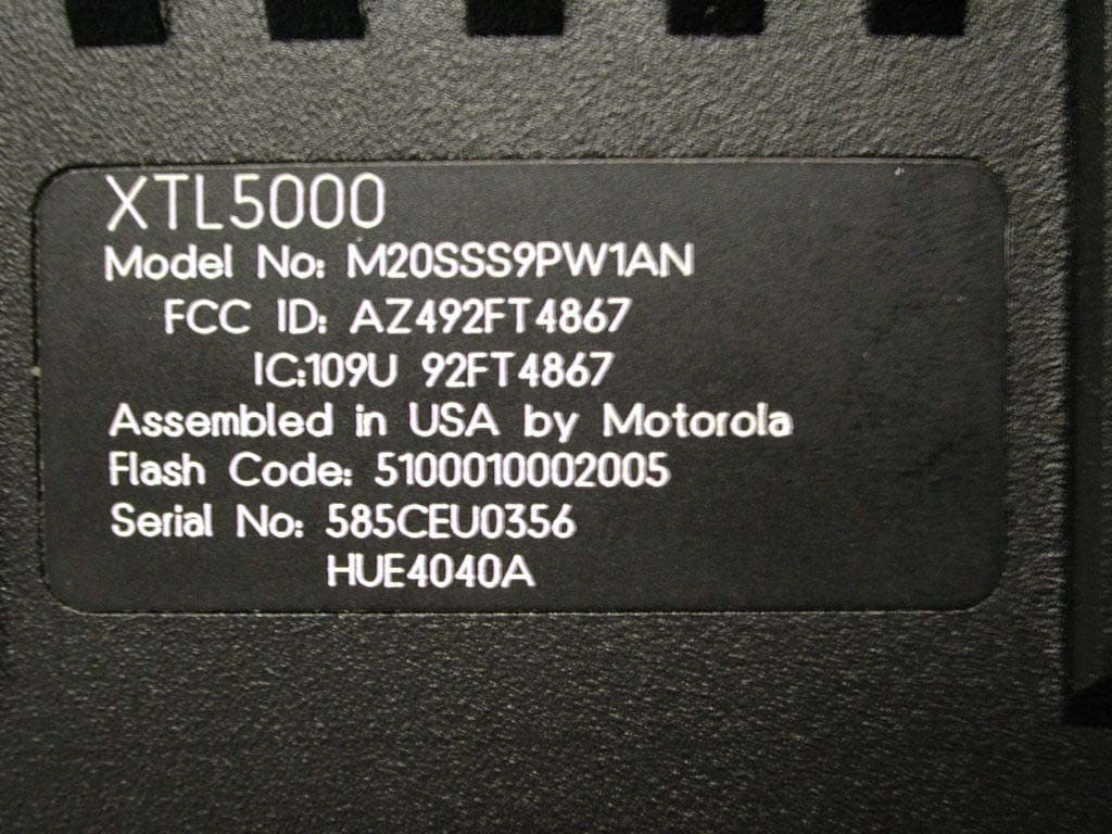
Click to zoom
Application Details
- Equipment Class
- TNB - Licensed Non-Broadcast Station Transmitter
- Date of Grant
- Dec 29, 2004
- Application Purpose
- Original Equipment
- Date of Application
- Jul 12, 2004
- Equipment Note
- Astro XTL 5000 Digital Mobile Radio
- Frequency Range
- 450.00000000 - 520.00000000
- Company
- Motorola Solutions, Inc.
- Country
- United States
Documents & Files
Document Text
Text extracted from the exhibit documents filed with the FCC. Open a document above to read the original.
Users Manual
W4, W5, W7, W9 Control Heads User's Guide ASTRO ® XTL TM 5000 Digital Mobile Radio ASTRO ® XTL™ 5000 Digital Mobile Radio with W4 Control Head Quick Reference Card BASIC OPERATIONTurning the Radio On and OffSetting the Volume and SquelchChanging ModesTransmittingTransmitting (Conventional Modes) Activating ScanProgramming a Scan ListSelecting Scan Mode Priority PHONE PAGE or SECURE or EMERGENCY Page Emer CALL DIRECT XMIT BUSY Mode Volume Pwr Phon Call Sel Scan Mic Home Dim H/L Dir Mon SCAN SELECT MONITOR MODE KNOB POWER ON/OFF/ VOLUME KNOB H OME H ORN/ LI GHTS PRIORITY/ NON-PRIORITY INDICATORS DIRECT INDICATOR Rotate the Vol (Volume) knob clockwise. 1 Turn the Vol knob clockwise to increase volume or counterclockwise to decrease volume as desired. 2 On conventional modes with Private-Line or Digital Private-Line, press Mon or remove the microphone from the hang-up clip to defeat the coded squelch. 3 Press Mon again, or replace the microphone on the hang-up clip to return to coded-squelch operation. 4 To adjust squelch level, hold Mon until a tone sounds. 5 Turn Mode knob to select squelch level. 6 Press Home . Turn the Mode knob to select the desired mode ORPress Home to access the preprogrammed Home mode. 1 Press and hold the microphone PTT button. 2 When the transmit light comes on solid and no alert tones sound (or a talk-permit tone or ID sidetone sounds), speak into the microphone in a normal voice. 3 State your FCC call sign at the beginning of each transmission. 1 Press Dir (Direct). The Dir indicator lights. 2 Press Dir again to return to repeater operation. 1 Press Scan to start a scan. If no activity exists, the display shows your selected mode. When a scanned channel or talkgroup becomes active, the display shows the active mode name. The PRI and NPRI indicators show priority. 2 Press Scan again to stop scanning. 1 Hold Scan until a tone sounds and the scan indicator blinks. 2 Turn the Mode knob to select the mode you want to program. 3 Press the Sel button as indicated in the table below to add or remove the displayed mode from the scan list. 4 Repeat the previous steps to continue editing the list. 5 Press Home or Scan to exit. Press Sel Mode Indicator One time Non-Priority NPRI lit Two times Second Priority PRI lit Three times First Priority PRI blinks Four times Delete from List No indicator 1 Press the Sel button as indicated in the table above to designate up to two modes as priorities. 2 Press Home or Scan to end scan list selection. Sending an Emergency Alarm or Call Sending a Status TransmissionSending a Direct-Entry Keyboard Status TransmissionSending a Direct-Entry Enhanced Private Conversation Call Initiating a Call Alert PageAnswering a Call Alert Page Press the emergency actuator ( Emer button, footswitch, hidden pushbutton) to begin an emergency transmission.For conventional modes, a silent or non-silent emergency alarm data transmission is sent.For trunked modes, emergency call (priority access to a voice channel), silent or non-silent emergency alarm, or emergency alarm and call is entered.Depending on your radio's programming, one of the emergency sequences described in the table below occur. Alarm Type Indications/Actions Non-Silent A tone sounds and the display alternates between EMERGNCY and the zone/channel. When acknowledged, four more tones sound and the display shows ACK RCVD , then the radio returns to normal operation. Silent The audio is muted and no display changes take place during the alarm. Press the PTT button, or press and hold the emergency button to stop the emergency condition and unmute the radio. Call (Trunked Modes only) A tone sounds and the display alternates between EMERGNCY and the zone/channel.Press the PTT button and talk. After completing the call, press and hold the emergency actuator until a tone sounds to return to normal operation. Alarm and Call After ACK RCVD (see Non-Silent Alarm above) is displayed, the radio has priority voice-channel access.Press the PTT button and talk. After completing the call, press and hold the emergency actuator until a tone sounds to return to normal operation. 1 Press Sts . The display shows the last acknowledged status or first status name. 2 Rotate Mode to select other statuses. 3 Press Sel to send the transmission. The display flashes the selected status/message name until the dispatcher acknowledges, at which time alert tones sound and the display shows ACK RCVD . The radio then returns to normal operation. Press the appropriate Sts # button you wish to send. The associated indicator blinks until an acknowledgment is received, then it lights steadily. 1 Press Sel or the PTT button. A single tone sounds and the display changes to PLS WAIT , followed by telephone-type ringing if the receiving unit is in service. Alarm Type Indications/Actions 2 If the receiving unit answers, press the PTT button to identify yourself and proceed with your call.ORIf the called unit does not respond, press Sel or the PTT button again to leave a Call Alert page message and your ID.A single tone followed by four tones sounds if the called unit acknowledges the page. 1 Press the Page button. 2 Follow the instructions for initiating a Private Conversation to select a unit ID. 3 Press Sel or the PTT button to send a Call Alert page to the displayed ID,ORTo send a Call Alert page following an Enhanced Private Conversation attempt, follow the instructions for sending a direct-entry Enhanced Private Conversation call. Four tones sound and PAGE RCV flashes on the display. The tone and display repeat every five seconds. 1 Press the PTT button, ORInitiate an Enhanced Private Conversation call to the caller. Selecting a Zone/Mode (Optional)Selecting a Home Zone/Home ModeSelecting Secure ModeSelecting an Encryption Key Selecting a Key IndexErasing an Encryption Key DISPLAY AND LIGHT INDICATORS 1 Press the Zone Up ! button or Zone Down " button to scroll to the desired zone. 2 Turn the Mode knob to select the mode. Press the Ho…
Text truncated - open the document above for the full version.
Users Manual
i zTitle Page ® XTL™ 5000 Digital Mobile Radio Installation Manual (Mid-Power and 100W Radios) Motorola, Inc. 8000 West Sunrise Boulevard Fort Lauderdale, Florida 33322 6881098C38-O ii Foreword This manual covers all models of the ASTRO ® XTL™ 5000 digital mobile radios (models W3, W4, W5, W7, and W9), unless otherwise specified. It includes all the information necessary to maintain peak product performance and maximum working time, using levels 1 and 2 maintenance procedures. This level of service goes down to the board replacement level and is typical of some local service centers, self-maintained customers, and distributors. For details on radio operation or component-level troubleshooting, refer to the applicable manuals available separately. A list of related publications is provided in the section “Related Publications,” on page vii. Product Safety and RF Exposure Compliance See “Installation Requirements for Compliance with Radio Frequency (RF) Energy Exposure Safety Standards,” on page iii. Manual Revisions Changes which occur after this manual is printed are described in FMRs (Florida Manual Revisions). These FMRs provide complete replacement pages for all added, changed, and deleted items. To obtain FMRs, go to https://businessonline.motorola.com. Parts Ordering See Appendix A: Replacement Parts Ordering for information on how to obtain replacement parts. For part numbers, refer to the ASTRO XTL 5000 Digital Mobile Radio Basic Service Manual (Motorola publication part number 6881096C73). Computer Software Copyrights The Motorola products described in this manual may include copyrighted Motorola computer programs stored in semiconductor memories or other media. Laws in the United States and other countries preserve for Motorola certain exclusive rights for copyrighted computer programs, including, but not limited to, the exclusive right to copy or reproduce in any form the copyrighted computer program. Accordingly, any copyrighted Motorola computer programs contained in the Motorola products described in this manual may not be copied, reproduced, modified, reverse-engineered, or distributed in any manner without the express written permission of Motorola. Furthermore, the purchase of Motorola products shall not be deemed to grant either directly or by implication, estoppel, or otherwise, any license under the copyrights, patents or patent applications of Motorola, except for the normal non-exclusive license to use that arises by operation of law in the sale of a product. Document Copyrights No duplication or distribution of this document or any portion thereof shall take place without the express written permission of Motorola. No part of this manual may be reproduced, distributed, or transmitted in any form or by any means, electronic or mechanical, for any purpose without the express written permission of Motorola. Disclaimer The information in this document is carefully examined, and is believed to be entirely reliable. However, no responsibility is assumed for inaccuracies. Furthermore, Motorola reserves the right to make changes to any products herein to improve readability, function, or design. Motorola does not assume any liability arising out of the applications or use of any product or circuit described herein; nor does it cover any license under its patent rights nor the rights of others. Trademarks MOTOROLA, the Stylized M logo, FLASHport, and ASTRO are registered in the US Patent & Trademark Office. All other product or service names are the property of their respective owners. © Motorola, Inc. 2004. iii Installation Requirements for Compliance with Radio Frequency (RF) Energy Exposure Safety Standards ATTENTION! This radio is intended for use in occupational/controlled conditions, where users have full knowledge of their exposure and can exercise control over their exposure to meet FCC limits. This radio device is NOT authorized for general population, consumer, or any other use. To ensure compliance to RF Energy Safety Standards: •Install only Motorola approved antennas and accessories •Be sure that antenna installation is per “Antenna Installation,” on page 2-22 of this manual •Be sure that Product Safety and RF Safety Booklet enclosed with this radio is available to the end user upon completion of the installation of this radio Before using this product, the operator must be familiar with the RF energy awareness information and operating instructions in the Product Safety and RF Exposure booklet enclosed with each radio (Motorola Publication part number 68P81095C99) to ensure compliance with Radio Frequency (RF) energy exposure limits. For a list of Motorola-approved antennas and other accessories, visit the following web site which lists approved accessories for your radio model: http://www.motorola.com/cgiss/index.shtml . This Page Intentionally Left Blank iv Table of Contentsv 6881098C38-OSeptember 30, 2004 Table of Contents Foreword .........................................................................................................ii Product Safety and RF Exposure Compliance ............................................................................................ii Manual Revisions ........................................................................................................................................ii Parts Ordering .............................................................................................................................................ii Computer Software Copyrights ...................................................................................................................ii Document Copyrights ..................................................................................................................................ii Disclaimer....................................................................................................................................................ii Trademarks ..............…
Text truncated - open the document above for the full version.
Users Manual
English Product Safety and RF Energy Exposure Booklet for Mobile Two-Way Radios Installed in Vehicles or as Fixed Site Control Stations ATTENTION! The information provided in this document supersedes the general safety information contained in user guides published prior to February 2002. BEFORE USING THIS RADIO, READ THIS BOOKLET WHICH CONTAINS IMPORTANT OPERATING INSTRUCTIONS FOR SAFE USAGE AND RF ENERGY AWARENESS AND CONTROL INFORMATION FOR COMPLIANCE WITH RF ENERGY EXPOSURE LIMITS IN APPLICABLE NATIONAL AND INTERNATIONAL STANDARDS. © Motorola, Inc. 2004 8000 W. Sunrise Blvd., Ft. Lauderdale, FL 33322 *6881095C99* 68P81095C99-C 2 English RF Energy Exposure Awareness and Control Information, and Operational Instructions for FCC Occupational Use Requirements NOTICE: This radio is intended for use in occupational/controlled conditions, where users have full knowledge of their exposure and can exercise control over their exposure to meet FCC limits. This radio device is NOT authorized for general population, consumer, or any other use. This 2-way radio uses electromagnetic energy in the radio frequency (RF) spectrum to provide communications between two or more users over a distance. It uses radio frequency (RF) energy or radio waves to send and receive calls. RF energy is one form of electromagnetic energy. Other forms include, but are not limited to, sunlight and x-rays. RF energy, however, should not be confused with these other forms of electromagnetic energy, which when used improperly, can cause biological damage. Very high levels of x-rays, for example, can damage tissues and genetic material. Experts in science, engineering, medicine, health, and industry work with organizations to develop standards for safe exposure to RF energy. These standards provide recommended levels of RF exposure for both workers and the general public. These recommended RF exposure levels include substantial margins of protection. All Motorola 2-way radios are designed, manufactured, and tested to ensure they meet government-established RF exposure levels. In addition, manufacturers also recommend specific operating instructions to users of 2-way radios. These instructions are important because they inform users about RF energy exposure and provide simple procedures on how to control it. 3 English Please refer to the following Web sites for more information on what RF energy exposure is and how to control your exposure to assure compliance with established RF exposure limits. http://www.fcc.gov/oet/rfsafety/rf-faqs.html http://www.osha.gov/SLTC/radiofrequencyradiation/index.html Federal Communication Commission Regulations The FCC rules require manufacturers to comply with the FCC RF energy exposure limits for mobile 2-way radios before they can be marketed in the U.S. When 2-way radios are used as a consequence of employment, the FCC requires users to be fully aware of and able to control their exposure to meet occupational requirements. Exposure awareness can be facilitated by the use of a label directing users to specific user awareness information. Your Motorola 2-way radio has a RF exposure product label. Also, your Motorola user manual, or separate safety booklet, includes information and operating instructions required to control your RF exposure and to satisfy compliance requirements. Compliance with RF Exposure Standard Your Motorola two-way radio is designed and tested to comply with a number of national and international standards and guidelines (listed below) regarding human exposure to radio frequency electromagnetic energy. This radio complies with the IEEE and ICNIRP exposure limits for occupational/controlled RF exposure environment at duty factors of up to 50% talk-50% listen and is authorized by the FCC for occupational use. In terms of measuring RF energy for compliance with the FCC exposure guidelines, your radio antenna radiates measurable RF energy only while it is transmitting (during talking), not when it is receiving (listening) or in standby mode. 4 English Your Motorola two-way radio complies with the following RF energy exposure standards and guidelines: • United States Federal Communications Commission, Code of Federal Regulations; 47CFR part 2 sub-part J • American National Standards Institute (ANSI) / Institute of Electrical and Electronic Engineers (IEEE) C95. 1-1992 • Institute of Electrical and Electronic Engineers (IEEE) C95.1-1999 Edition • International Commission on Non-Ionizing Radiation Protection (ICNIRP) 1998 • Ministry of Health (Canada) Safety Code 6. Limits of Human Exposure to Radiofrequency Electromagnetic Fields in the Frequency Range from 3 kHz to 300 GHz, 1999 • Australian Communications Authority Radiocommunications (Electromagnetic Radiation - Human Exposure) Standard, 2003 • ANATEL, Brasil Regulatory Authority, Resolution 256 (April 11, 2001) “additional requirements for SMR, cellular, and PCS product certification.” RF Exposure Compliance and Control Guidelines and Operating Instructions To control exposure to yourself and others and to ensure compliance with the RF exposure limits, always adhere to the following procedures. Guidelines: • User awareness instructions should accompany device when transferred to other users. • Do not use this device if the operational requirements described herein are not met. Instructions: •Transmit no more than the rated duty factor of 50% of the time. To t r a n s m i t (talk), push the Push-To-Talk (PTT) button or, for radios equipped with VOX, speak into the microphone. The red LED will illuminate when the radio is 5 English transmitting. To receive calls, release the PTT button, or, for radios equipped with VOX, stop talking. The red LED will extinguish when the radio stops transmitting. Transmitting 50% of the time, or less, is important because this radio generates measurable RF energy exposure only when transmitting (in terms of measuring for standards compliance). •Transmit only when people outside the vehicle a…
Text truncated - open the document above for the full version.
Attestation Statements
MOTOROLA INC FCC ID: AZ492FT4867 EXHIBIT 2 STATEMENT OF CERTIFICATION The technical data supplied with this application, having been taken under my supervision is hereby duly certified. The following is a statement of my qualifications: 1) BSEE McMaster University, Hamilton, Canada 2) 2 years experience in the development, testing and certification of Land Mobile Communications Products NAME: Kevin Krishnaratne SIGNED: /s/ Kevin Krishnaratne (signed) DATE: 07 th July 2004 POSITION: Senior Hardware Designer I hereby certify that the above application was prepared under my direction and that to the best of my knowledge and belief, the facts set forth in the application and accompanying technical data are true and correct: NAME: Matt Gimpelj SIGNED: /s/ Matt Gimpelj (signed) DATE: 07 th July 2004 POSITION: Engineering Manager
Cover Letter(s)
FCC ID: AZ492FT4867 ______________________________________________________________________________ 8000 West Sunrise Boulevard, Fort Lauderdale, Florida 33322. 12 th July 2004 Authorization & Evaluation Division Federal Communications Commission Laboratory 7435 Oakland Mills Road Columbia, MD 21046 Subject: Application for Certification of Transmitter with FCC ID: AZ492FT4867. Gentlemen: Motorola Inc, 8000 West Sunrise Boulevard, Fort Lauderdale, Florida, herein submits application for Certification of the subject transmitter. This transmitter is intended for use in a Mobile Radio environment with capabilities for clear and coded communications with a variable transmit power of 4-54 Watt. The transmitter will operate in the 450-520 MHz frequency band. We are requesting Certification under Part 22, 74, 80 and 90 of the Commission’s Rules to allow operation of this equipment. The subject transmitter complies with Section 90.203 of the Rules in that the operator cannot directly program transmit frequencies using the unit's normally accessible external controls. A complete Certification application is enclosed. If you require any additional information, please contact Mike Ramnath at (954) 723-5793 Sincerely, /s/ Mike Ramnath (signed) Mike Ramnath Manager, Regulatory Compliance Email: [email protected] EXHIBIT 13
Cover Letter(s)
FCC ID: AZ492FT4867 ______________________________________________________________________________ iDEN, Motorola Inc 8000 West Sunrise Boulevard, Fort Lauderdale, Florida 33322. (954) 723-5793 CONFIDENTIALITY REQUESTED Date: 12 th July 2004 Authorization & Evaluation Division Federal Communications Commission Laboratory 7435 Oakland Mills Road Columbia, MD 21046 Subject: Confidentiality Request for Transmitter with FCC ID: AZ492FT4867. Dear Sir or Madam: Motorola is requesting that Exhibit 4 (Circuit Descriptions), Exhibit 5 (Schematic Diagrams), Exhibit 10 (Parts List and Tune Up Procedures), and Exhibit 12 (Operational Description) not be made routinely available for public inspection. Motorola considers the information in these exhibits to be classified as trade secrets, pursuant to 47 CFR Section 0.457(d) and Section 552(b)(4) of the Freedom of Information Act. We are also requesting that the FCC mark Exhibit 3 (External Photos), 8a and 8b (Users Manual) and Exhibit 9, (Internal Photos) as Temporary or Short-Term Confidentiality as outlined in Public Notice DA 04-1705, dated June 15, 2004. This provision will give Motorola temporary confidentiality prior to product launch. Please mark Exhibits 4, 5, 10, and 12 as “Confidential” and Exhibit 3 (External Photos), 8a and 8b (Users Manual) and 9 (Internal Photos) as “Temporary Confidential”. Please contact me if you require any additional information. Sincerely, /s/ Mike Ramnath (signed) Manager, Regulatory Compliance Tel: (954) 723-5793 E-mail: [email protected] Exhibit 13b
Cover Letter(s)
FCC ID: AZ492FT4867 Date: 12th July 2004 Authorization & Evaluation Division Federal Communications Commission Laboratory 7435 Oakland Mills Road Columbia, MD 21046 Subject: Request for Grant Based on Alternative Measurement Procedure for Certification of Transmitter with FCC ID: AZ492FT4867. Dear Sir or Madam: This application respectfully requests a waiver of Sections 1.1310 and 2.1091(d) of the Commission’s rules. The subject transmitter was evaluated for compliance with the RF exposure limits by using both experimental measurements of field strength and computational modeling of specific absorption rates (SAR), as described below. Motorola requests that these combined data be deemed acceptable for equipment authorization of this device. As the Office of Engineering and Technology (OET) is aware, SAR is the fundamental measure of the rate of RF energy absorption and both the scientific basis and compliance metric for the Commission’s RF exposure guidelines. The MPE limits adopted by FCC— and used for RF evaluation procedures and exposure limits for mobile devices—are based on criteria quantified in terms of SAR. The scientific validity of using SAR computational modeling, either as a complement to or in lieu of MPE evaluations, should not be in question. The Commission has already concluded that computational modeling is a scientifically valid method to evaluate RF energy absorption in humans. The Commission’s Report and Order in ET Docket 93-62, FCC 96-326, 11 FCC Rcd.15123 (1996) provided “guidelines on the application of the exposure criteria to portable and mobile devices in general” (at 68). The R&O also concluded (at 70) that there were a number of “appropriate methods and techniques for determining SAR for compliance purposes,” that “the use of appropriate numerical and computational techniques, such as FDTD analysis, is acceptable for demonstrating compliance with SAR values” and that “such techniques offer valid means to determine energy absorption characteristics in exposed subjects.” EXHIBIT 13C SHEET 1 OF 2 EXHIBIT 13C SHEET 2 OF 2 Although the Report and Order’s acceptance of computational modeling was not expressly applied to mobile devices, the Commission’s Rules allow and its technical guidance encourages approval of acceptable, up-to-date measurement procedures. Section 2.947 (a)(3) of the Rules provides the Commission general discretion to accept data gathered by “[a]ny measurement procedure acceptable to the Commission.” FCC’s principal technical guidance, Supplement C to OET Bulletin 65 (Evaluating Compliance with FCC Guidelines for Human Exposure to Radiofrequency Electromagnetic Fields) encourages the use of “up-to-date test procedures” and makes clear that “other methods and procedures may be acceptable if based on sound engineering practice.” Simply making field strength measurements and calculating MPE values may result in data that overstate the actual RF energy absorption of persons nearby the device. In the case of the subject transmitter, for example, data for ten test conditions out of a total of fifty-two suggest that applicable MPE limits could be exceeded. Upon closer analysis, however, these conditions were demonstrated to be compliant. Appendix B describes how these ten test conditions were divided into two groups—bystander exposures and passenger exposures—and analyzed with a state of the art computational modeling method to determine compliance with the specific absorption rate (SAR) limits for general public exposure (1.6 W/kg averaged over 1 gram of tissue). This particular computational modeling technique is based on commercially available Finite-Difference- Time-Domain (FDTD) methodology. The data demonstrate that the SAR values for these ten test conditions are in fact compliant with the FCC limits for general public exposure. In summary, SAR is the fundamental measure of RF energy absorption and the scientific basis for FCC’s exposure evaluation guidelines. The Commission has concluded that computational modeling of SAR is a scientifically valid method to evaluate RF absorption. The attached data show that SAR modeling provides accurate exposure evaluations that can be used to demonstrate compliance for test conditions where field strength measurements suggest non-conformance. The Commission’s acceptance of computational modeling data for this device would serve the public interest by furthering the use of newer and more accurate technologies for RF exposure evaluation and by permitting the authorization of public safety radio equipment. Sincerely, /s/ Mike Ramnath (signed) Mike Ramnath Manager, Regulatory Compliance Phone: (954) 723-5793 Email: [email protected]
External Photos
MOTOROLA INC. FCC ID: AZ492FT4867 EXTERNAL PHOTOGRAPHS The following photographs are attached. 1. Front view (Controls) 2. Back view 3. Top view 4. RF exposure label (Close view) 5. Bottom view (FCC label location) 6. FCC label (Close view) 7. Side view (Left) 8. Side view (Right) MOTOROLA INC. FCC ID: AZ492FT4867 FRONT VIEW (CONTROLS) EXHIBIT 3-1 MOTOROLA INC. FCC ID: AZ492FT4867 BACK VIEW EXHIBIT 3-2 MOTOROLA INC. FCC ID: AZ492FT4867 TOP VIEW EXHIBIT 3-3 MOTOROLA INC. FCC ID: AZ492FT4867 RF EXPOSURE LABEL (CLOSE VIEW) EXHIBIT 3-4 MOTOROLA INC. FCC ID: AZ492FT4867 BOTTOM VIEW (FCC LABEL LOCATION) EXHIBIT 3-5 MOTOROLA INC. FCC ID: AZ492FT4867 FCC LABEL (CLOSE VIEW) MOTOROLA INC. FCC ID: AZ492FT4867 EXHIBIT 3-6 MOTOROLA INC. FCC ID: AZ492FT4867 SIDE VIEW (LEFT) EXHIBIT 3-7 MOTOROLA INC. FCC ID: AZ492FT4867 SIDE VIEW (RIGHT) EXHIBIT 3-8
ID Label/Location Info
MOTOROLA INC FCC ID: AZ492FT4867 LIST OF EXHIBITS DESCRIPTION EXHIBIT REFERENCE I. Identification label information 1 2.1033-(c) 11 & General Information 1a 1. Production Plans 2.1033-(c) 2. Application References 2.1061 3. Data Submittal Procedure II. Certification of Data 2 III. External Photographs 3 2.1033-(c) 12 IV. Block Diagrams (Circuit Diagrams) 4 V. Schematic Diagrams 5 2.1033-(c)-10 VI. Test Report 6 1. Data Index 6 2. RF Output Data 6A 2.1046 3. Modulation Characteristics 2.1047 A. Audio Response & Low Pass Filter Response 6B B. Low Pass Filter Response 6C C. Modulation Limiting 6D 4. Occupied Bandwidth 6E 2.1049 5. Conducted Spurious Emissions 6G 2.1051 6. Radiated Spurious Emissions 6H 2.1053 7. Frequency Stability (Temperature & Supply Voltage) 6I-1, 6I-2 2.1055 8. Transient Frequency Behavior 6J VII. Test Set-up Procedures 7 2.1041 VIII. Instruction Manual 8 2.1033-(c) 3 IX. Internal Photographs. 9 2.1033-(c) 11, 12 X. Parts List and Tune-Up procedures 10 2.1033-(c) 9, 10 XI. RF Exposure Information 11 2.1091 XII. Operational Description 12 2.1033-(c) 4, 5 1. Technical Characteristics 2. Application XIII. Cover Letter 13 MOTOROLA INC FCC ID: AZ492FT4867 IDENTIFICATION LABEL LOCATION See the Attached Photograph or Sketch X Back Of Radio Back Of Radio under Belt Clip TYPE X The label is a paper polyester film laminate with a pressure sensitive adhesive backing. The adhesive is a permanent type acrylic with a minimum peel strength of 40 oz/inch. MARKINGS (TEXT) X See the Attached Photograph and Exhibit 3-5 for the actual location of the FCC label on the device. Label Attached Below. See Attached Drawing. MOTOROLA INC FCC ID: AZ492FT4867 EXHIBIT 1 MOTOROLA INC FCC ID: AZ492FT4867 GENERAL INFORMATION I. Production Plans -- Pursuant 2.1033 (c) Quantity production is planned. II. Application References -- Pursuant 2.1061 Reference is made to the following Motorola "Application References" 1. Mobile Products and their application. 2. Mobile Products Transmitter Modulations Methods. 3. Plantation, Florida Antenna Range. III. Data Submittal Procedure: Data is supplied in accordance with Part 2, Sub-part J of the Commissions’ rules. Necessary Bandwidth Computation for 8K10F1E Emission Designator The FCC Rule & Regulations Part 2, §2.202(b) defines Necessary Bandwidth as the minimum value of the occupied bandwidth sufficient to ensure that transmission of information at the rate and with the quality required for the system employed. §2.202(c) lists four methods of determining the necessary bandwidth, including the use of formulas in §2.202(g), and measurement in cases where the other methods of §2.202(c) do not apply. It is felt that while these formulas apply well to …
Text truncated - open the document above for the full version.
Contact Information
Applicant
Arine Lee(Certification Manager)
Technical Contact
Motorola IncMike Ramnath
[email protected]954-723-5793
8000 West Sunrise Blvd · Plantation, Florida · United States
Technical Specifications
| # | Rule Parts | Frequency Range | Power Output | Emission | Tolerance |
|---|---|---|---|---|---|
| 9 | 22 | 450 MHz - 520 MHz | 54 W | 8K10F1D | 2 ppm |
Other Applications from Motorola Solutions, Inc.

AZ489FT4980
Sep 08, 2026Portable two way radio
Equipment Class
TNF - Licensed Non-Broadcast Transmitter Held to FaceAZ489FT4981
Aug 14, 2026Handheld Portable - TANAPA BPR 45 400-470 MHZ 4W NKP
Equipment Class
TNF - Licensed Non-Broadcast Transmitter Held to Face
AZ489FT7187
Jul 13, 2026Portable 2-Way Radio with Bluetooth, Bluetooth LE, WIFI 2.4GHz, WIFI 5GHz, LTE
Equipment Class
DSS - Part 15 Spread Spectrum TransmitterAZ499FT6031
May 11, 2026Operation Critical Wireless Earpiece PTT
Equipment Class
DSS - Part 15 Spread Spectrum Transmitter
AZ499FT5879
Dec 19, 20252-way Portable Radio with BT, BTLE, WIFI, NFC and LTE
Equipment Class
DSS - Part 15 Spread Spectrum Transmitter