AZ492FT5802Hand held Data Terminal with integral Mobitex
Motorola Solutions, Inc.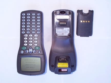
Click to zoom
Application Details
- Equipment Class
- TNT - Licensed Non-Broadcast Transmitter Worn on Body
- Date of Grant
- Feb 25, 2001
- Application Purpose
- Original Equipment
- Date of Application
- Oct 26, 2000
- Equipment Note
- Hand held Data Terminal with integral Mobitex
- Frequency Range
- 896.00000000 - 901.00000000
- Company
- Motorola Solutions, Inc.
- Country
- United States
Documents & Files
Document Text
Text extracted from the exhibit documents filed with the FCC. Open a document above to read the original.
Users Manual
Applicant: Motorola, Inc. FCC ID:AZ492FT5802 Exhibit 8 VIII. Instruction Manual 1.) Quick Reference Card HDT 500 Series 2.) Safety Warnings - Handheld Data Terminal, HDT Family Safe and Efficient Operation of Motorola Two Way Radio Products
Users Manual
Applicant: Motorola Inc. FCC ID:AZ492FT5802 Exhibit 8 Exhibit 8. Instruction Manual 1.) Quick Reference Card HDT 500 Series 2.) Safety Information - Handheld Data Terminal, HDT Family Safe and Efficient Operation of Motorola Two Way Radio Products Front Panel The HDT 500 Keys are assigned to operate according to the specific usage of the device. However, the items shown below refer to basic operations available in all HDT 500 configurations. Setting the Office Dock Local Computer Control A Large Office configuration enables a cascade connection of up to 31 Office Dock units (155 HDT 500 devices) to one RS-485 port in the host computer. For connections, see figure below. Remote Computer Control A Small Office configuration enables a cascade connection of up to 3 Office Dock units (15 HDT 500 devices) to the host computer. A Line Modem is used for communication with remote located host computer. For connections, see figure below. and Motorola are registered trademarks of Motorola Inc. © Motorola Inc., 2000 68P02 960C11-A @6802960C11@ To Third Office Dock Unit J2 J1 To 90-240VAC Power Outlet Line Modem (28.8 or 33.6kb/s) J1 RS-232 cables To Phone Line J2 To more Office Dock Units J3 J4 Host computer RS-485 cables J3 J4 RS-485 to RS-232 Converter Navigation Keys Screen Light (When pressed with Shift key, contrast level increases cyclically). IMPORTANT: To save battery power, use Screen Light only when needed. Barcode ScannerKeys (for left-hand and right-hand users) Screen Indication Light (Operation is defined by configuration) Space Key Space Key (Operation is defined by configuration) Battery Charge LED (see figure below) • No light - Not in use • Red light - Battery charging (6-9 hours for full capacity) • Green light - Battery fully charged Important Note Battery is considered damaged when charging takes more than 8 hours. Contact service to replace battery. Data Communication With Host (see figure above) Communication between the HDT 500 and the host computer can be established when the HDT 500 rests in the Office Dock. When data flows from the HDT 500 to the host computer, the Data Out yellow LED lights. When data flows from the host computer to the HDT 500, the Data In yellow LED lights. HDT 500 Series Hand-held Data Terminal with Wide Area Network Radio Modem And LASER Barcode Scanner Quick Reference Card Switching On Press the Power On/Off button for more than 2 seconds. The Power Indication Light will illuminate, indicating that the battery is O.K. and the device is operative. Switching Off Press the Power On/Off button for more than 2 seconds and release. The Power Indication Light will turn off. HDT 500 Holster Office Dock Power On/Off Button Keypad Screen Buzzer Battery Pack ( Do not remove) Indication Light Laser Scanner Infrared communication A perture (Keep clean using soft, damp cloth) CAUTION LASER LIGHT - DO NOT STARE INTO BEAM (Keep LASER window clean using soft, damp cloth) ! C a u t i o n 68P02960C25-O Please retain for future use Safe and Efficient Operation of Motorola Two Way Radio Products RF OPERATIONAL CHARACTERISTICS Your radio contains a transmitter which transmits using very short bursts of data;a receiver which receives radio frequency (RF); and an internal antenna. EXPOSURE TO RADIO FREQUENCY ENERGY Your Motorola radio product is designed to comply with the following national and international standards and guidelines regarding exposure of human be- ings to radio frequency electromagnetic energy: • United States Federal Communications Commission, Code of Federal Regulations; 47 CFR part 2 sub-part J • American National Standards Institute (ANSI) / Institute of Electrical and Electronic Engineers (IEEE) C 95. 1-1992 • Institute of Electrical and Electronic Engineers (IEEE), C95.1-1999 Edition • National Council on Radiation Protection and Measurements (NCRP) of the United States, Report 86, 1986 • International Commission on Non-Ionizing Radiation Protection (ICNIRP (1998) • National Radiological Protection Board of the United Kingdom, (1995) • Ministry of Health (Canada) Safety Code 6. Limits of Human Exposure to Radiofrequency Electromagnetic Fields in the Frequency Range from 3 kHz to 300 GHz, 1999 • Australian Communications Authority Radiocommunications (Electro- magnetic Radiation - Human Exposure) Standard 1999 (applicable to wireless phones only). To assure optimal radio product performance and to make sure human expo- sure to radio frequency electromagnetic energy is within the guidelines set forth in the above standards, always adhere to the following procedures: PORTABLE RADIO PRODUCT OPERATION & EME EXPOSURE BODY-WORN OPERATION To maintain compliance with FCC RF exposure guidelines, if you wear a radio product on your body when transmitting, always place the radio product in a Motorola supplied or approved clip, holder, holster, case, or body harness. Use of non-Motorola-approved accessories may exceed FCC RF exposure guidelines. If you do not use a body-worn accessory, and are not using the radio product held in the normal use position, ensure the radio product is at least one inch (2.5 cms) from your body when transmitting . APPROVED ACCESSORIES For a list of approved Motorola accessories, please refer to the Quick Refer- ence Card . ELECTROMAGNETIC INTERFERENCE / COMPATIBILITY NOTE : Nearly every electronic device is susceptible to electromagnetic inter- ference (EMI) if inadequately shielded, designed or otherwise configured for electromagnetic compatibility FACILITIES To avoid electromagnetic interference and/or compatibility conflicts, turn off your radio product in any facility where posted notices instruct you to do so. Hospitals or health care facilities may be using equipment that is sensitive to external RF energy . AIRCRAFT When instructed to do so, turn off your radio product when on board an air- craft. Any use of a radio product must be in accordance with airline regula- tions or airline crew instructions. HANDHELD DATA TERMINAL HDT …
Text truncated - open the document above for the full version.
Attestation Statements
FCC Certification Report for the FCC ID: AZ492FT5802 Hand Held Data Terminal New Certification Exhibit II. Certification Data
Cover Letter(s)
FCC Certification Report for the FCC ID: AZ492FT5802 Hand Held Data Terminal New Certification XIII. Cover Letter
Cover Letter(s)
RESEARCH IN MOTION Research In Motion Limited 295 Phillip Street Waterloo, Ontario Canada N2L 3W8 +1 519 888 7465, fax +1 519 888 6906 E-mail: [email protected] Our Ref: 01947-CERT-FCC-COVER-021January 23, 2001 Federal Communication Commission Equipment Authorization Division Application Processing Branch 7435 Oakland Mills Road Columbia, MD 21045 Reference :FCC ID : L6AR902M-2-O Subject :Letter requesting confidentiality of R902M-2-O radio modem device FCC Certification application. Pursuant to CFR 47 Chapter 1 Section 0.459, Research In Motion Limited (RIM) requests that the following identified detailed technical information regarding the R902M-2-O device be held confidential by the Federal Communication Commission (FCC) and as such be withheld from public inspection. RIM does not disclose proprietary confidential information about our products to any third parties and as such we request that the FCC does the same and forward the confidentiality acceptance letter to RIM. Our FCC submissions are considered proprietary confidential information. Pursuant to CFR 47 Chapter 1 Sections 0.457(d) and 0.457(d)(2)(i) the exhibits contain details of trade secrets and technical data that is customarily guarded from competitors and not released to the public by Research In Motion Limited. The specific parts of the Exhibits indicated in this letter are considered confidential by RIM and as such should be prevented from disclosure to public and competitors. RIM has taken necessary measures to have limited access to confidential documents only to RIM internal employees on a need-to-know basis, and have signed confidentiality agreements with employees. If the disclosure of such information is made public, it will cause serious competitive harm to RIM. Previously, none of the requested confidential Exhibits have been disclosed to third parties by RIM. The following Exhibits with specific sections described, submitted with the Form 731 Attachments should be held confidential: Exhibit Parts List/Tune Up InfoSection 010-9-1 and 010-9-2, CFR 47 Section 2.983(d)(9) - Description of operational, test, and device tune-up technical procedure-“DOC-01606-007”, and operators’ manual-“DOC- 01606-008” Section 010-10, CFR 47 Section 2.983(d)(10) - Description of frequency stabilizing circuitry Exhibit Parts List/Tune Up InfoSection 010-11-1, CFR 47 Section 2.983(d)(11) - Description of circuits for suppression of spurious radiation Section 010-11-2, CFR 47 Section 2.983(d)(11) - Description of circuits for modulation limiting Section 010-11-3, CFR 47 Section 2.983(d)(11) - Description of circuits for power limiting Exhibit Operational DescriptionSection 010-12 and 010-12-1, CFR 47 Section 2.983(d)(12) - Description of digital modulation format and necessary bandwidth Exhibit Parts List/Tune Up InfoSection 010-12-2 and 010-12-3, CFR 47 Section 2.983(d)(12) – Modulation generation methods and circuits. Detailed diagrams of modulation format and generation methods and circuits Exhibit Operational DescriptionSection 011-1 and 011-2, CFR 47 Sections 2.975(a)(3), 2.983(d)(6) and 2.1033(b)(4) - Detailed system and functional description Exhibit Parts List/Tune Up InfoSection 011-3, CFR 47 Sections 2.975(a)(3), 2.983(d)(6) and 2.1033(b)(4) - Detailed technical RF and electrical circuit description Exhibit Block Diagram01947-CERT-FCC-BLOCK-“R902M-2-O RADIO BLOCK”, CFR 47 Section 2.983(d)(6) – Detailed technical radio modem block diagram Exhibit Schematics“Tadpole OEM” SCH-01947-001, CFR 47 Section 2.983(d)(7) - Complete technical schematic circuit diagrams Yours truly, MasudS.Attayi,P.Eng. Senior Certification Engineer Research In Motion Limited ( 519 ) 888 – 7465 x 2442 [email protected] RESEARCH IN MOTION Research In Motion Limited 295 Phillip Street Waterloo, Ontario Canada N2L 3W8 +1 519 888 7465, fax +1 519 888 6906 E-mail: [email protected] Our Ref: 01947-CERT-FCC-Cover-022January 23, 2001 Federal Communications Commission Equipment Authorization Division Application Processing Branch 7435 Oakland Mills Rd. Columbia, Md. 21046 FCC ID:L6AR902M-2-O Subject:FCC Part 90 Certification Application for Research In Motion Limited, Model R902M-2-O This is to inform that Research In Motion is submitting the technical documentation of our radio modem Model R902M-2-O (existing FCC ID: L6AR902M-2-O ) in support of the application for Certification of our integrator, HDT515 with FCC ID AZ492FT5802. The Model R902M-2-O is a radio modem intended for integration into other equipment to allow wireless data communication. All required documents in compliance with Parts 2 and 90 of the FCC Rules have been provided in the attached Exhibits. Research In Motion would like to request confidentiality as indicated in the Form 731, Item 8 and as requested in the letter Ref: 01947-CERT-FCC-COVER-021, under Exhibit “Covering Letters”. Please do hesitate to call at (519) 888-7465 x2442 or email at [email protected] should you require additional information or have any questions. Yours truly, MasudS.Attayi,P.Eng. Senior Certification Engineer Research In Motion Limited ( 519 ) 888 – 7465 x 2442 [email protected]
External Photos
Applicant: Motorola Inc FCC ID:AZ492FT5802 EXHIBIT 3 III. External Photographs Photo 1. Front view & rear view with battery removed shows the FCC ID label location Applicant: Motorola Inc FCC ID:AZ492FT5802 EXHIBIT 3 See FCC Label magnified below. Applicant: Motorola Inc FCC ID:AZ492FT5802 EXHIBIT 3
ID Label/Location Info
Applicant: Motorola Inc. FCC ID:AZ492FT5802 Exhibit 1 LIST OF EXHIBITS DESCRIPTIONEXHIBITSREFERENCE I.Identification label Information12.983-(f) & General Information1a 1. Production Plans2.9811(a) 2. Application References2.1061 3. Data submittal Procedure II.Certification Data2 III.External Photographs32.983-(g) IV.Block Diagrams (Circuit Diagrams)4 V.Schematic Diagrams52.983-(d)-7 VI.Test Report6 1. Data Index6 2. RF Output Data6A 2.985 3. Modulation Characteristics2.987 A. Audio Response & Low Pass Filter Response* B. Modulation Limiting* 4. Occupied Bandwidth6E2.989 5. Conducted Spurious Emissions6F2.991 6. Radiated Spurious Emissions6G2.993 7. Frequency Stability (Temperature & Supply Voltage) *2.995 VII.Test Set-up Procedures72.999 VIII.Instruction Manual82.983-(d)-8 IX.Internal Photographs92.983-(g) X.Part List and Tune Up Procedures*2.983-(d)-6, 9 XI.RF Exposure Information112.1093 XII.Operational Description122.983-(d) 1,2,3,4,5 1. Technical Characteristics 2. Application XIII. Cover Letter13 • Please refer to the original data on file under FCC ID:L6AR902M-2-0 for these items. Applicant: Motorola Inc. FCC ID:AZ492FT5802 Exhibit 1 Exhibit 1. Identification Label ----- 47 CFR. 2.033(C) 11 LOCATION Back side of the transceiver unit chassis. TYPE The label is a paper polyester film laminate with a pressure sensitive adhesive backing. The adhesive is a permanent type acrylic with a minimum peel strength of 40 inches/oz. MARKINGS (TEXT) Enlarged view of FCC portion of label: Applicant: Motorola Inc. FCC ID:AZ492FT5802 Exhibit 1 Exhibit 1a. General Information----- 47 CFR. 2.1031, 2.1061. 1a.1.Production Plans -- Pursuant 47 CFR 2.1031 Quantity production is planned. 1a.2. Application References -- Pursuant 47 CFR 2.1061 Reference is made to the following Motorola "Application References" 1. Land Mobile Products and their application 1a.3. Data Submittal Procedure Data located in Exhibit 6 is supplied in accordance with Part 2, Sub-part J and Part 90, Sub-parts I and J of the Commissions’ rules and will be submitted electronically. 1a.4. Similar, currently Type Accepted Transmitter The HDT 515 device, manufactured by Motorola Inc, contains within an OEM radio modem that is FCC Type Accepted under the FCC ID: L6AR902M-2-O. The Grantee for the OEM radio modem is Research In Motion, Ltd.
Internal Photos
Applicant: Motorola, Inc. FCC ID:AZ492FT5802 Exhibit 9 IX. Internal Photographs Photo 1.Case open antenna, OEM module and cables in place. Photo 2. Antenna removed and top shield cover removed from CPU board. Photo 3.Bottom of OEM module bracket and bottom side of the CPU board view of lower shields. Photo 4.Back side of keypad, display and lower CPU shield. Applicant: Motorola, Inc. FCC ID:AZ492FT5802 Exhibit 9 Applicant: Motorola, Inc. FCC ID:AZ492FT5802 Exhibit 9
Internal Photos
Applicant: Motorola Inc FCC ID: AZ492FT5802 FCC Certification Report for the FCC ID: AZ492FT5802 Hand Held Data Terminal New Certification IX. Internal Photographs Photo 1.Case open antenna, OEM module and cables in place Photo 2. Antenna removed and top shield cover removed from CPU board Photo 3.Bottom of OEM module bracket and bottom side of the CPU board view of lower shields Photo 4.Back side of keypad, display and lower CPU shield Applicant: Motorola Inc FCC ID: AZ492FT5802 Applicant: Motorola Inc FCC ID: AZ492FT5802
RF Exposure Info
Applicant: Motorola, Inc. FCC ID: AZ492FT5802 Exhibit 11 RF EXPOSURE INFORMATION In accordance with 47 CFR 2.1091(c) this transmitter has been subjected to routine environmental evaluation for RF exposure and found to be compliant with the limits specified in 47 CFR 2.1091(d) using measurements per methods stated in 47 CFR 2.1091(d)(4).
RF Exposure Info
Applicant: Motorola Inc FCC ID: AZ492FT5802 Motorola Inc., 8000 West Sunrise Blvd., Plantation, FL 33322 Date: December 26, 2000 Mr. Andy Leimer and Mr. Kwok Chan Authorization & Evaluation Division Federal Communications Commission Laboratory 7435 Oakland Mills Road Columbia, MD 21046 Re: Correspondence Number 17159 regarding 731 Confirmation Number 99152 Gentlemen, This correspondence is provided in response to the request for information dated November 22, 2000 concerning transmitter with FCC ID: AZ492FT5802. Q1. Please upload a copy of the users manual containing the applicable RF exposure info for users to satisfy RF exposure requirements. R1. Amended Users Manual with the appropriate RF Exposure information is now uploaded to the OET Website. Q2. A cover letter from RIM (transmitter supplier) has been submitted with this filing indicating Motorola will submit SAR and ERP data. An RF exposure compliance statement has been submitted by Motorola indicating compliance with 2.1091. Please clarify the operating configurations and exposure conditions for this device, with respect to 2.1091/2.1093 of the rules for determining RF exposure requirements and uploaded the applicable RF exposure test data. R2. RF Exposure test report is uploaded. Q3. Please provide an illustration or photo indicating the location of the antenna within the device. If this device operates within 20 cm of persons, it should be considered as a portable transmitter. R3. See photo uploaded under the “RF Exposure” item as Exhibit 9. Applicant: Motorola Inc FCC ID: AZ492FT5802 Motorola Inc., 8000 West Sunrise Blvd., Plantation, FL 33322 Q4) The antenna is integral and built-in. Upload the required ERP data for the fundamental and spurious emissions. R4. See table below with ERP data. P/N Motorola 8586923T01 Model MARS MA8994-02VM Test Results - 21 June 2000Maximum Pout: 2.0 Watt, 33dBm Minimum Pout: 62 mW, 24.85dBm ERP=Pout+Peak Gain. Horizontal Tx Frequency (MHz)896902 Peak Gain (dBd)-3.1-3.1 ERP Maximum (mW) 977977 ERP Minimum (mW)151151 VerticalTx Frequency (MHz)896902 Peak Gain (dBd)-3.1-3.1 ERP Maximum (mW)977977 ERP Minimum (mW)151151 Contact me at (954) 723-5793 if you require any additional information. Regards, Mike Ramnath FCC Liaison Email: [email protected]
RF Exposure Info
1 ELECTROMAGNETIC EXPOSURE (EME) TESTING LABORATORY 8000 West Sunrise Blvd. Fort-Lauderdale, Florida S.A.R. TEST REPORT FCC ID : AZ492FT5802 (Handheld Data Terminal – HDT515-Model F5027A) December 12, 2000 - Rev. A Tested By: Jim Fortier Lead Engineer Prepared By: Stephen Whalen Senior Engineer Reviewed/Approved By: Ken Enger Senior Resource Manager Product Safety and EME Director 2 TABLE OF CONTENTS 1.0 Introduction 2.0 Applicable Regulations 3.0 Description of Test Sample 3.1 Antenna Description 3.1.1 Antenna Type 3.1.2 Antenna Location 3.1.3 Antenna Dimensions 3.1.4 Antenna Configuration 3.1.5 Antenna Gain 3.2 Test Signal 3.3 Test Frequency and Output Power 4.0 Description of Test Equipment 4.1 Measurement System Description 4.2 Description of Phantom 4.2.1 Full Body Phantom 4.3 Simulated Tissue Properties 4.3.1 Type of Simulated Tissue 4.3.2 Simulated Tissue Composition 5.0 Description of Test Procedure 5.1 Description of Test Positions 5.2 Probe Scan Procedures 6.0 Measurement Uncertainty 7.0 SAR Test Results 7.1 Measured SAR 7.2 Maximum Calculated SAR by Expected Operating Position and Conditions 3 TABLE OF CONTENTS (Cont.) 8.0 Conclusion Appendix A: Data Results Appendix B: Dipole Validation Data Result Appendix C: Measurement Probe Calibration Certificate 4 1.0 Introduction This report details the test setup, test equipment, and test results of the Specific Absorption Rate (SAR) measurement performed at CGISS EME Laboratory for the Handheld Data Terminal with wireless LAN, model number F5027A and evaluated to Occupational/Controlled Exposure limit of 8.0mW/g. The purpose for this revision is to update a second holster (FLN9202A) that was tested. 2.0 Applicable Regulations and Standards • United States Federal Communications Commission, Code of Federal Regulations; 47 CFR part 2 sub-part J • American National Standards Institute (ANSI) / Institute of Electrical and Electronic Engineers (IEEE) C95. 1-1992 • Institute of Electrical and Electronic Engineers (IEEE) C95.1-1999 Edition • National Council on Radiation Protection and Measurements (NCRP) of the United States, Report 86, 1986 • Ministry of Health (Canada) Safety Code 6. Limits of Human Exposure to Radiofrequency Electromagnetic Fields in the Frequency Range from 3 kHz to 300 GHz, 1999 3.0 Description of Test Sample The Handheld Data Terminal model number F5027A contains a 900 MHz Wireless LAN Radio, manufactured by RIM. The OEM Radio module (FCC ID L6AR902M-2-0) transmits in the Gaussian Minimum Shift Keying Mode (GMSK) with a maximum output of 2.0W at a maximum 25% transmit duty cycle. The HDT515 can operate in either a holster or hand-held in front of the operator. 3.1 Antenna Description: 3.1.1 Antenna type: Quarter wave internal. 5 Monopole X Dipole Helix Patch Other 3.1.2 Antenna Location on Device Left Right Top X Bottom Front Back X 3.1.3 Antenna Dimensions Length - cm (internal) 6.78 3.1.4 Antenna Configuration Fixed Retractable External Internal X 3.1.5 Antenna Gain Mode: Internal -2.0dBi 3.2 Test Signal Test Signal Source: Test Mode X Base Station Simulator Other Signal Modulation: CW X 3.3 Test Frequency and Output Power Output power measurement conditions: Free Space Radiated SAR test configuration X ConductedX Other 6 Output Power measured with: Power meter Base Station Simulator Spectrum AnalyzerX Other Test Frequency (MHz) Measured Power before SAR (W) Measured Power after SAR (W) 898.5 0.120 0.120 4.0 Description of Test Equipment 4.1 Descriptions of SAR Measurement System The laboratory utilizes a Dosimetric Assessment System (DASY) SAR measurement system manufactured by Schmid & Partner Engineering AG (SPEAG™), of Zurich Switzerland. This system utilizes a computer controlled six axis robot to move a measurement probe to measure the SAR. The SAR measurements were conducted with the probe ET3DV6 serial number 1384. It was calibrated at SPEAG™, and has a calibration date June 1, 2000. A copy of the calibration certificate is included as appendix C. Dipole Validation Kit type 925MHz (serial number 925-002) was used to validate the system accuracy at 925MHz. DIPOLE VALIDATION RESULT Dipole Antenna (S/N) Validation Type (Freq/Tissue) SAR Meas. @ 0.5W (w/ drift) Calculated SAR @ 1W Target SAR @ 1W 925-002 925MHz - Muscle 6.06 mW/g 12.12 mW/g 11.98 mW/g ± 10% The Dipole validation table indicated the result is within the required accuracy of ± 10% (Dipole SAR Validation for Dipole S/N 925-002) and thus the measured SAR values are considered correct. See appendix B for printout of the validation test results from the DASY measurement system. The DASY system is operated per the instructions in the DASY Users Manual. The entire manual is available directly from SPEAG. 4.2 Description of Phantom Human shaped, solid shell device made of fiberglass and mounted on a nonmetallic base or stand. 7 4.2.1 Full Body Phantom Abdomen Thickness 0.15 cm Face Thickness 0.15 cm 4.3 Simulated Tissue Properties: 4.3.1 Type of Simulated Tissue Full Body Phantom Muscle X 4.3.2 Simulated Tissue Composition 925MHz Di-Water 53.5 % Sugar 44.25% Salt 1.15% HEC 1.00 % Dowicil75 0.10 % Note: HEC (HYDROXYETHYL CELLULOSE) is a gelling agent and Dowicil 75 is anti bacterial compound. Characterization of Simulated tissue materials and ambient conditions: Simulated tissue prepared for SAR measurements are measured at room temperature and verified to be in spec prior to actual SAR measurements by filling a coaxial slotted line with the tissue and probing the amplitude and phase changes versus distance in the simulated tissue. A HP8753D Network Analyzer is used to perform the measurements. Measured simulated tissue dielectric constant and conductivity used in SAR runs as of 09/18/00. 8 Muscle 925 MHz Di-electric Constant 49.6 Conductivity – S/m 1.17 5.0 Description of Test Procedure The test procedure was design for standard operating configuration. The first test demonstrates the HDT515 in the FLN9623A holster, which can be attached to the use…
Text truncated - open the document above for the full version.
RF Exposure Info
Applicant: Motorola Inc FCC ID: AZ492FT5802 Motorola Inc., 8000 W. Sunrise Blvd., Plantation, FL 33322 Date: February 12, 2001. Mr. Andy Leimer and Mr. Kwok Chan Authorization & Evaluation Division Federal Communications Commission Laboratory 7435 Oakland Mills Road Columbia, MD 21046 Re: Correspondence Number 17711 regarding 731 Confirmation Number EA99152 Gentlemen; This correspondence is provided in response to the request for information dated January 16, 2001 concerning transmitter with FCC ID: AZ492FT5802. Q1. The SAR report indicates this device uses a transmitter that operates at 25% duty factor. The OEM transmitter, L6AR902M-2-O, was originally granted without duty factor restriction; please provide the applicable supporting info to qualify for source-based time-averaging. A1. The OEM transmitter has a newer version of radio code since its original grant. This version of code (2.0.19) restricts the HDT to a maximum transmit duty cycle of 25%. i.e. 1 data burst can only occur for 0.96ms, and then the unit waits at minimum 2.88s (3*0.96ms) before the next transmission. This information was provided by the OEM Product Manager from Research In Motion (RIM) Q2. Please provide photos for the two holsters described in the SAR report. SAR was tested with the front of the device facing the user's body, placed in one of the holsters (FLN9623A). Please indicate on the photos or with separate illustrations that the device, by design, can only be inserted into these two holsters with its front facing the user. Otherwise, test in the other configurations would be needed. Applicant: Motorola Inc FCC ID: AZ492FT5802 Motorola Inc., 8000 W. Sunrise Blvd., Plantation, FL 33322 A2. Two photos are submitted at this time and both photos indicate that the HDT will only fit in the holster with the keypad facing the user. Photo 1 illustrates a side view of the Photo 2 illustrates a side view of the HDT515 HDT515 with Holster FLN9623A. with Holster FLN9202A. Q3. The SAR repot describes holster FLN9202A has an additional strap with three metallic buttons on it but the other holster (FLN9623A) has been used for the SAR tests. Please verify that the metallic buttons on the holster that has not been tested do not affect the SAR results measured using FLN9623A and the two holsters are otherwise the same. If not, additional SAR tests may be needed. A3. Holsters FLN9202A and FLN9623A were both tested as indicated in the SAR report, Revision A, Dec. 12, 2000 (refer to section 5.0). However, only the holster that caused the highest measured SAR was reported. Refer to A5 for data comparison. Q4. FYI - The dielectric constant used in the SAR tests is lower than those usually used at this frequency, please use appropriate parameters for future filings. Since it is not expected to result in non-compliance issues, additional tests are not requested. A4. No response is required. Q5. The device was tested for SAR at 120 mW conducted output. The original filing for the OEM transmitter is rated at 2.0 W. The output used in the SAR tests corresponds to a duty factor of 6%, which is substantially lower than the 25% duty factor indicated in the SAR report. Please repeat all applicable SAR tests using the actual duty factor and signal timing sequences applicable for this device or at least repeat a subset of the tests to demonstrate that SAR scaling is appropriate for this device. Applicant: Motorola Inc FCC ID: AZ492FT5802 Motorola Inc., 8000 W. Sunrise Blvd., Plantation, FL 33322 A5. Hardware and software modified to provide sustained transmission in the native signaling mode, 25% maximum duty cycle, was not available at the time of test. An acceptable alternative was to test at 500mW CW, which is equivalent to 2W maximum output power at a 25% maximum duty cycle. The data below was measured with the HDT515 operating at 500mW in CW mode and demonstrates that the Power: SAR scaling is appropriate for this device. Scaling was calculated in section 7.2 of the SAR report. Holster Power SAR measured SAR maximum calculated FLN9623A 0.120W 0.03 mW/g 0.13 mW/g FLN9623A 0.500W 0.14 mW/g 0.14 mW/g FLN9202A 0.500W 0.13 mW/g 0.13 mW/g Q6. FYI - The SAR report has indicated this device has been tested with respect to occupational exposure limit. Please be aware that if the device complies with general population exposure limit, there is no need to use a more relaxed limit that could require additional operating restrictions. A6. At this time Motorola would like to exercise the opportunity to revise the exposure limit for this device to “General Population at 1.6 mW/g”. A revised SAR report (revision B) to reflect this change is submitted at this time. Contact me at (954) 723-5793 if you require any additional information. Regards, Mike Ramnath FCC Liaison Email: [email protected]
RF Exposure Info
1 ELECTROMAGNETIC EXPOSURE (EME) TESTING LABORATORY 8000 West Sunrise Blvd. Fort-Lauderdale, Florida S.A.R. TEST REPORT FCC ID # AZ492FT5802 (Handheld Data Terminal – HDT515-Model F5027A) February 08, 2001 - Rev. B Tested By: Jim Fortier Lead Engineer Prepared By: Stephen Whalen Senior Engineer Reviewed/Approved By: Ken Enger Senior Resource Manager Product Safety and EME Director 2 TABLE OF CONTENTS 1.0 Introduction 2.0 Applicable Regulations 3.0 Description of Test Sample 3.1 Antenna Description 3.1.1 Antenna Type 3.1.2 Antenna Location 3.1.3 Antenna Dimensions 3.1.4 Antenna Configuration 3.1.5 Antenna Gain 3.2 Test Signal 3.3 Test Frequency and Output Power 4.0 Description of Test Equipment 4.1 Measurement System Description 4.2 Description of Phantom 4.2.1 Full Body Phantom 4.3 Simulated Tissue Properties 4.3.1 Type of Simulated Tissue 4.3.2 Simulated Tissue Composition 5.0 Description of Test Procedure 5.1 Description of Test Positions 5.2 Probe Scan Procedures 6.0 Measurement Uncertainty 7.0 SAR Test Results 7.1 Measured SAR 7.2 Maximum Calculated SAR by Expected Operating Position and Conditions 3 TABLE OF CONTENTS (Cont.) 8.0 Conclusion Appendix A: Data Results Appendix B: Dipole Validation Data Result Appendix C: Measurement Probe Calibration Certificate REVISION HISTORY Date Revision Comments 10…
Text truncated - open the document above for the full version.
Contact Information
Applicant
Deanna Zakharia(Regulatory Compliance Manager)
Technical Contact
Spectrum Technology IncRod Munro
[email protected]425 771-4482
209 Dayton Street · Edmonds, Washington · United States
Non-Technical Contact
Motorola IncMike Ramnath
[email protected]954 723-5793
Test Firm
Spectrum Technology Inc.Rod Munro
Technical Specifications
| # | Rule Parts | Frequency Range | Power Output | Emission | Tolerance |
|---|---|---|---|---|---|
| 1 | 90 | 896 MHz - 901 MHz | 977.00 mW | 12K8F1D | 1.5000000000 ppm |
Other Applications from Motorola Solutions, Inc.

AZ489FT4980
Sep 08, 2026Portable two way radio
Equipment Class
TNF - Licensed Non-Broadcast Transmitter Held to FaceAZ489FT4981
Aug 14, 2026Handheld Portable - TANAPA BPR 45 400-470 MHZ 4W NKP
Equipment Class
TNF - Licensed Non-Broadcast Transmitter Held to Face
AZ489FT7187
Jul 13, 2026Portable 2-Way Radio with Bluetooth, Bluetooth LE, WIFI 2.4GHz, WIFI 5GHz, LTE
Equipment Class
DSS - Part 15 Spread Spectrum TransmitterAZ499FT6031
May 11, 2026Operation Critical Wireless Earpiece PTT
Equipment Class
DSS - Part 15 Spread Spectrum Transmitter
AZ499FT5879
Dec 19, 20252-way Portable Radio with BT, BTLE, WIFI, NFC and LTE
Equipment Class
DSS - Part 15 Spread Spectrum Transmitter