AZ492FT5826Integrated Transceiver (IDEN iO1500R)
Motorola Solutions, Inc.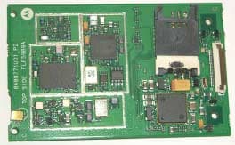
Click to zoom
Application Details
- Equipment Class
- TNB - Licensed Non-Broadcast Station Transmitter
- Date of Grant
- Jul 09, 2003
- Application Purpose
- Original Equipment
- Date of Application
- Jul 09, 2003
- Equipment Note
- Integrated Transceiver (IDEN iO1500R)
- Frequency Range
- 806.00000000 - 821.00000000
- Company
- Motorola Solutions, Inc.
- Country
- United States
Documents & Files
Document Text
Text extracted from the exhibit documents filed with the FCC. Open a document above to read the original.
Users Manual
iDEN Data Module iO1500R Application and Integration Developers Guide Release 1.3 May 15, 2003 Documentation Copyrights No duplication or distribution of this document or any portion thereof shall take place without the express written permission of Motorola. No part of this manual may be reproduced, distributed, or transmitted in any form or by any means, electronic or mechanical, for any purpose without the express written permission of Motorola. To order additional copies contact your Motorola sales representative. © 2003 Motorola All rights Reserved 68P02954C65-O 20/5/03 page 1 of 37 DECLARATION OF CONFORMITY Per FCC CFR 47 part 2 Section 2.1077(a) Hereby declares that the product: Conforms to the following regulation: FCC Part 15, subpart B Class B Computer Peripheral Device Date: MAY 15, 2003 Responsible party name: Motorola Inc. Address: 8000 West Sunrise Boulevard, Plantation, FL 33322 USA Phone number: 1 (800) 453-0920 Product name: iO1500R Model Number: F2572A FCC ID: AZ492FT5826 Note: This equipment has been tested and found to comply with the limits for a Class B digital device, pursuant to part 15 of the FCC Rules. These limits are designed to provide reasonable protection against harmful interference in a residential installation. This equipment generates, uses and can radiate radio frequency energy and, if not installed and used in accordance with the instructions, may cause harmful interference to radio communications. However, there is no guarantee that interference will not occur in a particular installation. If this equipment does cause harmful interference to radio or television reception, which can be determined by turning the equipment off and on, the user is encouraged to try to correct the interference by one or more of the following measures: -- Reorient or relocate the receiving antenna. -- Increase the separation between the equipment and receiver. -- Connect the equipment into an outlet on a circuit different from that to which the receiver is connected. -- Consult the dealer or an experienced radio/TV technician for help. 20/5/03 page 2 of 37 DECLARATION OF CONFORMITY..................................................................................2 Revision History.......................................................................................................................5 Purpose Of This Document......................................................................................................5 Distribution...............................................................................................................................5 Related Documentation............................................................................................................5 Module Descriptions and Specifications.................................................................................6 iO15 Modem Product Specificationss......................................................................6 Electrical specifications:........................................................................................6 Environmental Specifications................................................................................6 Other Specifications...............................................................................................6 iO1500R Evaluation board......................................................................................................7 Safety Notice - ATTENTION.................................................................................................7 FCC Regulation - Letter of Notice.............................................................................7 iO1500R Hardware Interfacing Information.........................................................................8 Mechanical Dimensions.............................................................................................8 Connector Types:.......................................................................................................9 Accessory Connector Pin Functions........................................................................10 Status LED Indications............................................................................................12 Voice Support..........................................................................................................12 Design Considerations For iO1500R OEM Developers......................................................13 Hardware Considerations.........................................................................................13 Software Considerations..........................................................................................13 Module Software And Interface Modes...............................................................................14 Circuit Switched Data..........................................................................................14 Packet Data..........................................................................................................14 Managing User Image Profiles..............................................................................................15 Warning When Switching User Image Profiles.......................................................15 Setting The Active User Image................................................................................15 Properly configuring, saving, and restoring user image profiles.............................16 Changing the settings of a user image.................................................................16 Restoring the settings of a saved user image.......................................................16 How To Use Hayes Compatible Packet Data mode.............................................................17 How to use Hayes Compatible Packet Data mode (Continued)..........................19 Other Useful AT Commands......................................................................…
Text truncated - open the document above for the full version.
Attestation Statements
FCC Filing Package for Motorola iO1500R OEM Integrated Transceiver FCC ID: AZ492FT5826 iDEN, Motorola Inc., 8000 West Sunrise Blvd., Plantation, FL 33322, USA http://ml800.motorola.com/ http://www.mot.com/iden Page:2-1 Exhibit 2. Statement of Certification—Pursuant to 47 CFR 2.907 The technical data supplied with this application, having been taken under my supervision is hereby duly certified. The following is a statement of my qualifications: B.Sc in Electrical Engineering, 1997, Ben Gurion University, Israel M.Sc in Electrical Engineering, 1999, Ben Gurion University, Israel 5 years experience in RF design and measurement techniques NAME: Shuki Levy SIGNATURE: /s/ Shuki Levy (signed) DATE: 2 nd June 2003 POSITION: RF Engineer I hereby certify that the above application was prepared under my direction and that to the best of my knowledge and belief, the facts set forth in the application and accompanying technical data are true and correct. NAME: Shirazi Gadi SIGNATURE: /s/ Shirazi Gadi (signed) DATE: 2 nd June 2003 POSITION: HW Development Manager
Cover Letter(s)
Applicant: Motorola Inc FCC ID: AZ492FT5826 24th June 2003 Authorization & Evaluation Division Federal Communications Commission Laboratory 7435 Oakland Mills Road Columbia, MD 21046 Dear Sir Motorola Inc., 8000 West Sunrise Boulevard, Fort Lauderdale, Florida 33322, herein submits its application for Certification of the transmitter with FCC ID: AZ492FT5826. This OEM (Original Equipment Manufacturer) integrated transceiver module uses similar circuitry and software utilized in a previously certified iO1000 integrated transceiver module with FCC ID: AZ489FT5796. Certification is sought for, and performance data is provided. This transceiver module will be marketed as an Original Equipment Manufacturer (OEM) to be embedded in a variety of end products, as described in 47 CFR 2.1091(d)(4). It is supplied neither with battery nor antenna, only with an antenna connector. The characteristics of having an antenna connector and no antenna are like those of transmitters classified as a mobile device, as defined in 47 CFR 2.1091(b), rather than a handheld portable device as defined in 47 CFR 2.1093(b). Thus, this module was environmentally evaluated for RF Exposure as a mobile device, and was found to be compliant with the MPE General Population limits for a mobile device in Table 1(B) of 47 CFR 2.1310 as required by 47CFR 2.1091(c). This module will be marketed to OEMs, who will integrate it into their equipment, i.e. lap-top computers, portable/mobile terminals, vending machines, etc. Since the end product may, in some cases, be used within a digital device such as a laptop computer to be marketed in the United States, it is our expectation that the end product may bear a separate FCC identifier in accordance with 47 CFR 2.925(b). It will be the responsibility of the integrator to conduct appropriate RF exposure evaluation, develop user manual information and obtain FCC equipment authorization for the end product. It is our intention to provide the OEM party with a letter notifying them of the need to comply with 47 CFR part 2 subpart J, et. el., once a purchasing agreement has been reached. This transceiver is of the receive-first type described in International Telecommunications Union Recommendation ITU-R M.1221 entitled Technical And Operational Requirements For Cellular Multimode Mobile Radio Stations. It must first find, acquire and lock onto a control channel from a predefined set of control channel frequencies assigned to a companion Authorized base station (e.g. – FCC ID: ABZ89FC5792). Transmission is not possible until lock to a base station control channel has been achieved, and then transmission is limited to digitally modulated service request bursts on the reverse control channel. Upon recognition of a proper request, the control channel base station transmitter will then assign the transceiver a traffic channel for transmission of digital iDEN, Motorola Inc., 8000 West Sunrise Blvd., Plantation, FL 33322, USA http://ml800.motorola.com/ http://www.mot.com/iden Page: 13- 1 Applicant: Motorola Inc FCC ID: AZ492FT5826 voice, circuit-switched data or Packet-switched data from the set of frequencies for which the trunking system is licensed. It is expected that this time division multiplexed transceiver marketed in the United States will also be used for itinerant operation with companion Authorized Base Stations by users requesting trunked radio and telephone interconnect service while roaming outside the United States. In some countries the companion base stations are licensed to operate at frequencies in the 821-825/866- 870 MHz band in addition to some of those in the 806-821/851-866 MHz band normally used in United States SMR systems. Consequently, this transmitter has been designed to meet FCC requirements for operation in the 806-821 MHz band over the more global band of 806 - 825 MHz when used with a companion Authorized Base Station. Thus, performance data is provided to substantiate FCC compliant operation with a Companion Base Station over the broader 806 to 825 MHz band expected for global use of this module. To facilitate global roaming it is kindly requested that a note be provided in the Grant, which states that this ‘receive first’ type of equipment is compliant for transmitter operation over the broader range 806-825 MHz when used with a compatible Authorized Base Station. This will aid equipment authorization in foreign countries, which accept a United States FCC Grant for Equipment Authorization, yet not jeopardize United States public safety or cellular systems licensed to operate in the 821-825 MHz frequency band since no compatible base station may be authorized on those frequencies in the United States. Enclosed is a complete Certification Application comprised of 13 Exhibits. Contact me at (954) 723- 5793 if you require any additional information. Regards, /s/ Mike Ramnath (signed) FCC Liaison Email: [email protected] iDEN, Motorola Inc., 8000 West Sunrise Blvd., Plantation, FL 33322, USA http://ml800.motorola.com/ http://www.mot.com/iden Page: 13- 2
Cover Letter(s)
FCC ID: AZ492FT5826 Motorola Inc., 8000 W. Sunrise Blvd., Plantation, FL 33322 Page: 13-3 REQUEST FOR CONFIDENTIALITY 24th June 2003 Authorization & Evaluation Division Federal Communications Commission Laboratory 7435 Oakland Mills Road Columbia, MD 21046 Subject: Application for Type Acceptance of Transmitter with FCC ID: AZ492FT5826. Gentlemen; Motorola is requesting that Exhibit 4 (Circuit Description), Exhibit 5 (Schematic Diagrams), Exhibit 8 (Dev. Manual), Exhibit 10 (Semiconductor/Active Device List) and Exhibit 12 not be made routinely not be made routinely available for public inspection. Exhibit 8 is sold to Developers. Pursuant to Sections 0.457 and 0.459 of the Commission's Rules, we hereby request confidential treatment of information accompanying this application as outlined below. Please mark Exhibit 4, 5, 8, 10 and 12 as Confidential. Contact me at (954) 723-5793 if you require any additional information. Regards, /s/ Mike Ramnath (signed) FCC Liaison Email: [email protected]
External Photos
FCC Filing Package for Motorola iO1500R OEM Integrated Transceiver FCC ID: AZ492FT5826 iDEN, Motorola Inc., 8000 West Sunrise Blvd., Plantation, FL 33322, USA http://ml800.motorola.com/ http://www.mot.com/iden Page: 3- 1 Exhibit 3. External Photographs -- Pursuant to 47 CFR 2.1033(c) 12 External photograph are identical to the internal photographs shown in Exhibit 9.
ID Label/Location Info
FCC Filing Package for Motorola iO1500R OEM Integrated Transceiver FCC ID: AZ492FT5826 iDEN, Motorola Inc., 8000 West Sunrise Blvd., Plantation, FL 33322, USA http://ml800.motorola.com/ http://www.mot.com/iden Page: 1- 1 Exhibit 1. Identification Label -- Pursuant to 47 CFR 2.925, 2.1065 and 2.1033(c)11 1.1. Location Back side of the transceiver unit chassis. (See the attached photograph 3.5 in exhibit 3) 1.2. Type The label is a white polyester film laminate with a pressure sensitive adhesive backing. The adhesive is a permanent type acrylic with minimum peel strength of 5 lbs/in. 1.3. Markings (Text) Enlarged view of label (showing FCC ID and manufacturer type number): Exhibit 1A. General Information 1A.1. Production Plans Quantity production is planned. 1A.2. Application References -- Pursuant to 47 CFR 2.948 and 2.1061 Reference is made to the following Motorola "Application References" Hermon Labs, located in Binyamina Israel is listed with FCC and Industry Canada as follows: 1. FCC OATS registration number is: 90623 2. FCC Anechoic chamber registration number is: 13040/SIT 1300F2 3. Industry Canada OATS registration number is: IC 2186-1 4. Industry Canada anechoic chamber registration number is: IC 2186-2 5. Accredited by A2LA. 1A.3. Data Submittal Procedure Data located in Exhibit 6 is supplied in accordance with Part 2, Sub-part J and Part 90, Sub-part I and Sub-part S of the Commission’s rules. 1A.4. Similar, currently Type Accepted Transmitter: FCC ID: AZ489FT5796
Internal Photos
FCC Filing Package for Motorola iO1500R OEM Integrated Transceiver FCC ID: AZ492FT5826 iDEN, Motorola Inc., 8000 West Sunrise Blvd., Plantation, FL 33322, USA http://ml800.motorola.com/ http://www.mot.com/iden Page: 9- 1 Exhibit 9. Internal Photographs -- Pursuant to 47 CFR 2.1033(c)12 Photograph 9-1: Front side of module main board. Photograph 9-2: Front side of module main board with shields removed. Photograph 9-3: Back side of module main board. Photograph 9-4: Back side of module main board with shields removed.
Parts List/Tune Up Info
FCC Filing Package for Motorola iO1500R OEM Integrated Transceiver FCC ID: AZ492FT5826 iDEN, Motorola Inc., 8000 West Sunrise Blvd., Plantation, FL 33322, USA http://ml800.motorola.com/ http://www.mot.com/iden Page: 10- 1 CONFIDENTIALITY REQUESTED Exhibit 10. Semiconductor/Active Device List and Tune up Procedure 10.1 Semiconductor/Active Device List Schematic KEY MOTOROLA PART # VENDOR PART # Device Type Circuit Application Operating Frequency Source Q303 4805793Y01 NE68519-T1 NPN TRANSISTOR Main VCO 956.90– 979.65 MHz NEC Q304, Q305 4805793Y01 NE68519-T1 NPN TRANSISTOR Main VCO buffer 956.90– 979.65 MHz NEC Y901 4805875Z04 AXTN6049A 16.8 MHz Crystal Oscillator Main FGU Reference Offset 16.8 MHz CPD L303 4805911Z06 DRR060KE1R180PC 1180 MHz ResonatorMain VCO 1180 MHz MURATA D200 4805656W28 BBY5802W DIODE VARACTOR Oscillator Main VCO 956.90– 979.65 MHz Infineon U500 5105385Y89 CX77207 IC PA 806-825 MHz Conexant D505 4809948D12 BAR63-02W DIODE RF PIN Antenna RX/TX Switch 806-870 MHz Infineon D504 4809948D12 BAR63-02W DIODE RF PIN Antenna RX/TX Switch 806-870 MHz Infineon U506 5185963A90 SC1614VFR2 IC Mixer/PLL/Cartesian feedback 806-825MHz Motorola SPS Q502 4805793Y01 NE68519-T1 NPN TX Offset VCO 309.3MHz CEL D500 4809877C08 1SV279TPH3 Varactor TX Offset VCO Tuner 309.3MHz Toshiba D381 4805656W26 1SV302TPH3 Varactor Ref VCO Tuner 16.8MHz Toshiba U302 5185765 AD7314 IC Temp sensor 1.2MHz Analog Devices U601 5185130C81 MAX515ESA-T IC Tuner control (DAC) 8.4MHz Maxim Q301 4805793Y01 NE68519-T1 NPN 2 nd LO VCO 219.3MHz CEL D300 4809877C08 1SV279TPH3 Varactor 2 nd LO tuner 219.3MHz Toshiba U600 5185127C02 SC51634VFR2 IC Synthesizer/DAC/Ref Osc/mixer 956.90– 979.65 MHz 16.8/109.65 Motorola SPS U801 5199472A01 PC56674VHR2 IC DSP / CPU 67.2 Motorola SPS U001 5109879E62 TWL93002AGHHR IC Power Management 19.44MHz, 0.262MHz Texas Instruments COMMENTS: The Motorola designators are special code numbers for active devices used in Motorola radios. These devices are either identical or derived from the device family listed under Source, by the manufacturer or are proprietary to Motorola. Service people do not have access to any cross-references or given any information on proprietary devices and are prevented from making unauthorized substitution. 10.2 Tune Up Procedure ----47 CFR. 2.1033(c)(9) All adjustments are software controlled and pre-set at the factory. The service concept is of field replaceable modem substitution. When a modem is determined to be faulty it is replaced. The faulty modem is then forwarded to a high technology center. There it is repaired and retuned using the same procedure as the factory.
RF Exposure Info
FCC Filing Package for Motorola iO1500R OEM Integrated Transceiver FCC ID: AZ492FT5826 iDEN, Motorola Inc., 8000 West Sunrise Blvd., Plantation, FL 33322, USA http://ml800.motorola.com/ http://www.mot.com/iden Page: 11- 1 Exhibit 11. RF EXPOSURE INFORMATION The characteristics of having an antenna connector and no antenna are like those of transmitters classified as a mobile device, as defined in 47 CFR 2.1091(b), rather than a handheld portable device as defined in 47 CFR 2.1093(b). Thus, this module was environmentally evaluated for RF Exposure as a mobile device, and was found to be compliant with the MPE General Population limits for a mobile device in Table 1(B) of 47 CFR 2.1310 as required by 47CFR 2.1091(c).
Test Report
FCC Filing Package for Motorola iO1500R OEM Integrated Transceiver FCC ID: AZ492FT5826 iDEN, Motorola Inc., 8000 West Sunrise Blvd., Plantation, FL 33322, USA http://ml800.motorola.com/ http://www.mot.com/iden Page: 6-1 Exhibit 6. Measured Data ----- 47 CFR. 2.1033(c) 14 6.1 RF Power Output Data -- Pursuant 47 CFR 2.1046(a), 2.1033(c)(6), 2.1033(c)(7) and 2.1033(c)(8 ) The RF power output was measured with the indicated voltage applied to and current into the final RF amplifying device (U503). The power Voltage and current given are averaged in the transmission time slot. At maximum output power setting: Output RF power 0.7 Watts (Pulse average) DC Voltage 4.1 Volts (Pulse average) DC Current 850 mA (Pulse average) RF PA Input Power 0.19 milliWatts (Pulse average) At the minimum power setting: Output RF power 0.7 milliWatts (Pulse average) DC Voltage 4.0 Volts (Pulse average) DC Current 500 mA (Pulse average) RF PA Input Power 0.2 microWatts (Pulse average) 6.2 Modulation Characteristics Data -- Pursuant 47 CFR 2.1047 and 2.1033(c)(13) Digitally encoded speech or digital data is transmitted in four sub-channels at a 4 kHz rate using M-ary symbols mapped to predetermined fixed magnitude and phase components within 1 of 3 constellations associated with a particular modulation scheme. Figure 6-2 illustrates symbol mapping to one of the four QPSK sub-channels constellations. Figure 6-3 illustrates symbol mapping to one of the four 16QAM sub-channels constellation. Figure 6-4 illustrates symbol mapping to one of the four 64QAM sub-channels constellation. For Quad-QPSK modulation, this mapping adjusts the amplitude and phase variations of the baseband signal to one of 4 points on the constellation. For Quad-16QAM modulation, this mapping adjusts the amplitude and phase variations of the baseband signal to one of 16 points on the constellation. For Quad-64 modulation, this mapping adjusts the amplitude and phase variations of the baseband signal to one of 64 points on the constellation. After conversion by the D/A converters in U401 (see Figure 4-3 in Exhibit 4), the necessary bandwidth of the sub-channels is limited to 4.8 kHz by the pair of modulation limiting low pass filters. The transfer response of these filters is depicted in Figure 6-1 where the filter excess bandwidth coefficient of 0.2 is shown. This excess bandwidth leads to the necessary bandwidth calculation of (1 + 0.2) x (4 kHz) = 4.8 kHz. Since the sub-channels are spaced 4.5 kHz apart, the necessary bandwidth of the composite 4 sub-channel symbol streams is 4.8 + (3 x 4.5) = 18.3 kHz. FCC Filing Package for Motorola iO1500R OEM Integrated Transceiver FCC ID: AZ492FT5826 iDEN, Motorola Inc., 8000 West Sunrise Blvd., Plantation, FL 33322, USA http://ml800.motorola.com/ http://www.mot.com/iden Page: 6-2 0.707 02k2.4k-2k H(f)=root raised cosine α=0 . 2 Modulation Low Pass Filter Response WoW where Wo = 2000 andW=(1+α)Wo = 2400Hz 1 for |f|<2Wo-W H (f)=cos 2 (š/4(|f|+W-2Wo)/(W-Wo)) for 2Wo-W <|f|<W 0 for |f|>W { Figure 6-1: Modulation Low Pass Filter Response x jy +1+3-1 -3 +1 +3 -3 -1 θ θθ θ Symbol Mapping onto One of Four Q PSK Constellations QAM baseband output ready for impression onto a particular subcarrier. Data Source QPSK Encoder Interleaver Subchannel Formatter Modem Interface Bit Stream Complex Symbol Stream Figure 6-2: Symbol Mapping onto One of Four QPSK Constellations FCC Filing Package for Motorola iO1500R OEM Integrated Transceiver FCC ID: AZ492FT5826 iDEN, Motorola Inc., 8000 West Sunrise Blvd., Plantation, FL 33322, USA http://ml800.motorola.com/ http://www.mot.com/iden Page: 6-3 x jy +1+3-1-3 +1 +3 -3 -1 θ θθ θ Symbol Mapping onto One of Four 16-Q AM Constellations QAM baseband output ready for impression onto a particular subcarrier. Data Source 16QAM Encoder Real to Complex Combiner Interleaver Modem Interface Bit Stream Complex Symbol Stream Subchannel Formatter Real Symbol Stream Figure 6-3: Symbol Mapping onto One of Four 16-QAM Constellations x jy +.5 +3.5-.5-3.5 +.5 +3.5 -3 .5 -.5 θ θθ θ Symbol Mapping onto One of Four 64-QAM Constellations QAM baseband output ready for impression onto a particular subcarrier. Data Source 16QAM Encoder Real to Complex Combiner Interleaver Modem Interface Bit Stream Complex Symbol Stream Subchannel Formatter Real Symbol Stream 0 1 -2.0 +2.0 .5 + Figure 6-4: Symbol Mapping onto One of Four 64-QAM Constellations FCC Filing Package for Motorola iO1500R OEM Integrated Transceiver FCC ID: AZ492FT5826 iDEN, Motorola Inc., 8000 West Sunrise Blvd., Plantation, FL 33322, USA http://ml800.motorola.com/ http://www.mot.com/iden Page: 6-4 6.3 Occupied Bandwidth Data -- Pursuant 47 CFR 2.1049, 90.210(g) and 90.691 The method described in paragraph 7.2 was employed with the following conditions: For Quad-QPSK Modulation: 32K Bits Per Second Pseudo-Random Digital Modulation. Vertical division: 10 dB/div. Carrier Reference: Carrier Reference 0 dB corresponds to maximum and minimum output power. For Quad-16QAM Modulation: 64K Bits Per Second Pseudo-Random Digital Modulation Vertical: 10 dB/div Carrier Reference: Carrier Reference 0 dB corresponds to maximum and minimum output power. For Quad-64QAM Modulation: 96K Bits Per Second Pseudo-Random Digital Modulation Vertical: 10 dB/div Carrier Reference: Carrier Reference 0 dB corresponds to maximum and minimum output power. In Figures 6-5 through Figure 6-16, trace 2 (transmitter performance) was measured using a resolution bandwidth of 300 Hz, while trace 1 (reference level) was obtained using a resolution bandwidth of 100 kHz. Trace 3 is the applicable emission mask. Mask 47 CFR 90.210(g) Measured Data Refer to Figures 6-5 and 6-6 for Quad-QPSK Modulation performance. Refer to Figures 6-7 and 6-8 for Quad-16QAM Modulation performance. Refer to Figures 6-9 and 6-10 for Quad-64QAM Modulation performance. Mask 47 CFR 90.691(a) Measured Data Refer to Figures 6-11and 6-12 for Quad-QPSK Modulation performance. Refer to Figures 6-13 and 6-14 for Quad-1…
Text truncated - open the document above for the full version.
Test Report
FCC Filing Package for Motorola iO1500R OEM Integrated Transceiver FCC ID: AZ492FT5826 - - iDEN, Motorola Inc., 8000 West Sunrise Blvd., Plantation, FL 33322, USA http://ml800.motorola.com/ http://www.mot.com/iden Page:6- 12 6.4 Conducted Spurious Emissions Data -- Pursuant 47 CFR 2.1051, 2.1057, 90.210 (g) and 90.691. FCC Emission Limit: less than -13 dBm Description Frequency (MHz) Measured Power (dBm) Margin to FCC Spec (dB) IF 154.65 <-33 > 20 2*IF 309.3 <-33 > 20 LO 960.6625 -26 13 IF + LO 1115.3125 <-33 > 20 2 X Fund 1612.025 -24.37 11.37 3 X Fund 2418.0375 <-33 > 20 4 X Fund 3224.05 <-33 > 20 5 X Fund 4030.0625 <-33 > 20 6 X Fund 4836.075 <-33 > 20 7 X Fund 5642.0875 <-33 > 20 8 X Fund 6448.1 <-33 > 20 9 X Fund 7254.1125 <-33 > 20 10 X Fund 8060.125 <-33 > 20 Table 6-1: Transmitter Conducted Spurious Emissions Data. Maximum Output Power Setting, Fundamental Frequency 806.0125 MHz FCC Filing Package for Motorola iO1500R OEM Integrated Transceiver FCC ID: AZ492FT5826 - - iDEN, Motorola Inc., 8000 West Sunrise Blvd., Plantation, FL 33322, USA http://ml800.motorola.com/ http://www.mot.com/iden Page:6- 13 Figure 6-17: Transmitter Conducted Spurious Emissions Plot. Maximum Output Power Setting, Fundamental Frequency 806.0125 MHz At minimum power setting, Conducted emissions were at least 20 dB below FCC limit. FCC Filing Package for Motorola iO1500R OEM Integrated Transceiver FCC ID: AZ492FT5826 - - iDEN, Motorola Inc., 8000 West Sunrise Blvd., Plantation, FL 33322, USA http://ml800.motorola.com/ http://www.mot.com/iden Page:6- 14 Description Frequency (MHz) Measured Power (dBm) Margin to FCC Spec (dB) IF 154.65 <-33 > 20 2*IF 309.3 <-33 > 20 LO 968.1625 -33 20 IF + LO 1122.8125 <-33 > 20 2 X Fund 1627.025 -27.907 14.907 3 X Fund 2440.5375 <-33 > 20 4 X Fund 3254.05 <-33 > 20 5 X Fund 4067.5625 <-33 > 20 6 X Fund 4881.075 <-33 > 20 7 X Fund 5694.5875 <-33 > 20 8 X Fund 6508.1 <-33 > 20 9 X Fund 7321.6125 <-33 > 20 10 X Fund 8135.125 <-33 > 20 Table 6-2: Transmitter Conducted Spurious Emissions Data. Maximum Output Power Setting, Fundamental Frequency 813.5125 MHz Figure 6-18: Transmitter Conducted Spurious Emissions Plot. Maximum Output Power Setting, Fundamental Frequency 813.5125 MHz At minimum power setting, Conducted emissions were at least 20 dB below FCC limit. FCC Filing Package for Motorola iO1500R OEM Integrated Transceiver FCC ID: AZ492FT5826 - - iDEN, Motorola Inc., 8000 West Sunrise Blvd., Plantation, FL 33322, USA http://ml800.motorola.com/ http://www.mot.com/iden Page:6- 15 Description Frequency (MHz) Measured Power (dBm) Margin to FCC Spec (dB) IF 154.65 <-33 > 20 2*IF 309.3 <-33 > 20 LO 979.6375 -31 18 IF + LO 1134.2875 <-33 > 20 2 X Fund 1649.975 <-33 > 20 3 X Fund 2474.9625 <-33 > 20 4 X Fund 3299.95 <-33 > 20 5 X Fund 4124.9375 <-33 > 20 6 X Fund 4949.925 <-33 > 20 7 X Fund 5774.9125 <-33 > 20 8 X Fund 6599.9 <-33 > 20 9 X Fund 7424.8875 <-33 > 20 10 X Fund 8249.875 <-33 > 20 Table 6-3: Transmitter Conducted Spurious Emissions Data. Maximum Output Power Setting, Fundamental Frequency 824.9875 MHz Figure 6-19: Transmitter Conducted Spurious Emissions Plot. Maximum Output Power Setting, Fundamental Frequency 824.9875 MHz At minimum power setting, Conducted emissions were at least 20 dB below FCC limit. FCC Filing Package for Motorola iO1500R OEM Integrated Transceiver FCC ID: AZ492FT5826 - - iDEN, Motorola Inc., 8000 West Sunrise Blvd., Plantation, FL 33322, USA http://ml800.motorola.com/ http://www.mot.com/iden Page:6- 16 6.5 Frequency Stability Data -- Pursuant 47 CFR 2.1055a(1), 2.1055(d)2 Measurements were made per method described in paragraph 7.4. Because of the transmitter’s dependence on the stability of the base station oscillator, it is not possible to provide stability data for this transmitter as is commonly supplied for certification per 47 CFR 2.1055 for a radio with a locally stabilized oscillator. The following information is provided to clarify how the transmitter attains the necessary accuracy of 2.5 PPM or better. The transmitter’s suppressed carrier emission is produced by mixing of a modulated intermediate frequency with a higher, digitally synthesized injection frequency with a resolution of 12.5 kHz. Both of these frequencies are derived from a temperature compensated crystal oscillator (Y300 in Figure 4-1). Transmission frequency accuracy is enhanced by the radio receiver circuitry, which causes the radio operating frequency to become locked to within 0.4 PPM of the base station once it has acquired the primary control channel. The AFC routine and frequency locking mechanism are implemented using both hardware and software. The hardware and software combined provide an automatic frequency control function, which locks the receiver to within 0.4 PPM of the control channel oscillator. Since the base station stability is FCC regulated to be 1.5 PPM or better, the absolute accuracy of the transmitter is inherently better than 1.9 PPM. This is accomplished by programming U601 while the radio is in operation. Transmitter frequency stability is guaranteed …
Text truncated - open the document above for the full version.
Contact Information
Applicant
Deanna Zakharia(Regulatory Compliance Manager)
Test Firm
MotorolaWilliam Elliott
Technical Specifications
| # | Rule Parts | Frequency Range | Power Output | Emission | Tolerance |
|---|---|---|---|---|---|
| 1 | 90 | 806 MHz - 821 MHz | 1.45 W | 18K3D7W | 1.9000000000 ppm |
Other Applications from Motorola Solutions, Inc.

AZ489FT4980
Sep 08, 2026Portable two way radio
Equipment Class
TNF - Licensed Non-Broadcast Transmitter Held to FaceAZ489FT4981
Aug 14, 2026Handheld Portable - TANAPA BPR 45 400-470 MHZ 4W NKP
Equipment Class
TNF - Licensed Non-Broadcast Transmitter Held to Face
AZ489FT7187
Jul 13, 2026Portable 2-Way Radio with Bluetooth, Bluetooth LE, WIFI 2.4GHz, WIFI 5GHz, LTE
Equipment Class
DSS - Part 15 Spread Spectrum TransmitterAZ499FT6031
May 11, 2026Operation Critical Wireless Earpiece PTT
Equipment Class
DSS - Part 15 Spread Spectrum Transmitter
AZ499FT5879
Dec 19, 20252-way Portable Radio with BT, BTLE, WIFI, NFC and LTE
Equipment Class
DSS - Part 15 Spread Spectrum Transmitter