AZ492FT5847MOBILE 2-WAY RADIO
Motorola Solutions, Inc.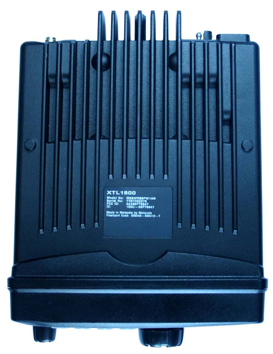
Click to zoom
Application Details
- Equipment Class
- TNB - Licensed Non-Broadcast Station Transmitter
- Date of Grant
- May 29, 2007
- Application Purpose
- Original Equipment
- Date of Application
- May 29, 2007
- Equipment Note
- MOBILE 2-WAY RADIO
- Frequency Range
- 935.00000000 - 940.00000000
- Company
- Motorola Solutions, Inc.
- Country
- United States
Documents & Files
Document Text
Text extracted from the exhibit documents filed with the FCC. Open a document above to read the original.
Users Manual
ASTRO ® XTL™ 1500 Digital Mobile Radio with Control Head Quick Reference CardProduct Safety and RF Exposure Compliance ATTENTION! This radio is restricted to occupational use only to satisfy FCC RF energy exposure requirements. Before using this product, read the RF energy awareness information and operating instructions in the Product Safety and RF Exposure booklet enclosed wit h your radio (Motorola Publication part number 6881095C99) to ensure compliance with RF energy exposure limits. BASIC OPERATIONTurning the Radio On and OffSelecting the Zone and ModeMonitoring Conventional ModesCancelling MonitoringReceivingTransmitting (Conventional Modes) Transmitting (Trunked Systems) LED INDICATIONS Before using this product, read the operating instructions for safe usage contained in the Product Safety and RF Exposure booklet enclosed with your radio. ! C a u t i o n Mode Knob Programmable Button (T1) 4 Soft Menu Keys LED Indicators Speaker LCD Display Volume / Power Knob GCAI Rotate the Volume knob clockwise to turn it on. When the radio is powered on, the display shows XTL 1500 . You will hear a high-pitched (good power-up) tone.If your radio shows an error on power-up, contact your system manager for assistance. 1 Press the ZNUP softkey or ZNDN softkey to scroll to the desired zone. 2 Press CHAN and rotate the Mode knob to select the mode. Press the preprogrammed Monitor button. The display shows MON ON . Press the preprogrammed Monitor button. The display shows MON OFF . 1 Select the desired zone and mode.2 Turn the Volume knob to adjust the volume. 1 Select the desired zone and mode.2 Rotate the Volume knob to adjust the volume. 3 When a mode becomes available, press and hold the PTT button to transmit; release the PTT button to receive. 1 Select the desired zone and mode.2 Rotate the Volume knob to adjust the volume. 3 Press and hold the PTT button to transmit; release the PTT button to receive. Action LED Condition Meaning Press the PTT button to transmit Steady red Normal transmission Unlit Not transmitting Release the PTT button to receive Steady yellow Channel activity present Blinking green Call Receive 96C67_Text.book Page 1 Thursday, March 1, 2007 8:54 AM STATUS ANNUNCIATORSThese are small symbols that appear on the display indicating the status of certain radio functions. GENERAL FEATURESStatus (Trunking Systems Only)Selecting Transmit Power LevelSending an Emergency AlarmSending a Silent Emergency Alarm Cancelling an Emergency AlarmSending an Emergency CallFailsoft Operation (Trunked Systems Only) Carrier Squelch ( C ) Indicates carrier squelch is open to monitor all active conventional mode traffic. When not displayed, traffic is not open to monitoring. Secure Operation ( D ) (Secure radios only) When solid, radio is transmitting securely.When blinking, radio is receiving securely.When off, radio is operating in clear mode. Call Received ( F ) Blinks when a Private Call, page, or Phone Call is received. Scan ( G ) When displayed, indicates the radio is scanning. Priority Scan ( H ) Indicates scanning of a priority mode (blinking for Priority 1 mode; solid for Priority 2 mode). RSSI M Radio Signal Strength. Programming/View Mode ( I ) When solid, radio is in view mode.When blinking, radio is in programming mode. Direct ( J ) When on, indicates you are talking directly to another radio (talkaround).When off, you are talking through a repeater. Tx Power Level ( R ) Transmission power of the radio is low. PPP Link Establishment Indicates that the subscriber is ready to receive data through a data cable. Packet Data activity Indicates the subscriber is transmitting and receiving data. Packet Data IP Indicates the subscriber is ready to access the FNE ***. 1 Press STS . The display shows the last acknowledged status or first status name. 2 Rotate the Mode knob to select the desired status. 3 Press the PTT button to transmit the selected status. 4 Press the EXIT softkey to exit status and return to the home display. 1Press m below PWR . The display shows HIGH PWR or LOW PWR . 2If HIGH PWR was selected previously, pressing the softkey will display LOW PWR and the low power indicators are turned on. 3If LOW PWR was selected previously, pressing the softkey will display HIGH PWR and the low power indicators are turned off. Press and hold the preprogrammed emergency button ( T1 ).The red LED lights steadily. You hear an emergency tone. The display alternately shows EMERGNCY and the current zone and mode names. When the alarm is acknowledged by the dispatcher, you hear four beeps. The radio returns to normal operation. Press and hold the preprogrammed emergency button ( T1 ). The radio transmits the emergency without any external indication than an alarm is in progress. Press and hold the preprogrammed emergency button ( T1 ) before the alarm is acknowledged. You hear an exit tone and the radio returns to normal operation. If the radio does not return to normal operation, press the PTT button. The radio does NOT sound an exit tone. 1 Press and hold the preprogrammed emergency button ( T1 ).The red LED lights steadily. You hear a short, medium-pitched emergency tone. The display alternately shows EMERGNCY and the current zone and mode names. 2 Press the PTT button and announce your emergency. 3 To exit emergency call mode, press the emergency button for a little over 1-1/2 seconds (or for the duration specified by your system manager). You hear a medium-pitched exit tone and the radio returns to normal operation During Failsoft operation, you hear a faint beeping tone every ten seconds. The radio unsquelches. The display alternately shows FAILSOFT and the current trunked mode name. 96C67_Text.book Page 2 Thursday, March 1, 2007 8:54 AM ScanningTurning Scan On or OffDeleting Nuisance ModesTelephone OperationAnswering a Telephone Call TRUNKING FEATURESDisplaying the ID NumberPrivate Conversation™ II, Enhanced Private Conversation™, and Call AlertCalling or Paging the Last ID Number Transmit…
Text truncated - open the document above for the full version.
Users Manual
English Product Safety and RF Energy Exposure Booklet for Mobile Two-Way Radios Installed in Vehicles or as Fixed Site Control Stations ATTENTION! The information provided in this document supersedes the general safety information contained in user guides published prior to February 2002. BEFORE USING THIS RADIO, READ THIS BOOKLET WHICH CONTAINS IMPORTANT OPERATING INSTRUCTIONS FOR SAFE USAGE AND RF ENERGY AWARENESS AND CONTROL INFORMATION FOR COMPLIANCE WITH RF ENERGY EXPOSURE LIMITS IN APPLICABLE NATIONAL AND INTERNATIONAL STANDARDS. © Motorola, Inc. 2005 8000 W. Sunrise Blvd., Ft. Lauderdale, FL 33322 *6881095C99* 68P81095C99-E 2 English RF Energy Exposure Awareness and Control Information, and Operational Instructions for FCC Occupational Use Requirements NOTICE: This radio is intended for use in occupational/controlled conditions, where users have full knowledge of their exposure and can exercise control over their exposure to meet FCC limits. This radio device is NOT authorized for general population, consumer, or any other use. This 2-way radio uses electromagnetic energy in the radio frequency (RF) spectrum to provide communications between two or more users over a distance. It uses radio frequency (RF) energy or radio waves to send and receive calls. RF energy is one form of electromagnetic energy. Other forms include, but are not limited to, sunlight and x-rays. RF energy, however, should not be confused with these other forms of electromagnetic energy, which when used improperly, can cause biological damage. Very high levels of x-rays, for example, can damage tissues and genetic material. Experts in science, engineering, medicine, health, and industry work with organizations to develop standards for safe exposure to RF energy. These standards provide recommended levels of RF exposure for both workers and the general public. These recommended RF exposure levels include substantial margins of protection. All Motorola 2-way radios are designed, manufactured, and tested to ensure they meet government-established RF exposure levels. In addition, manufacturers also recommend specific operating instructions to users of 2-way radios. These instructions are important because they inform users about RF energy exposure and provide simple procedures on how to control it. 3 English Please refer to the following Web sites for more information on what RF energy exposure is and how to control your exposure to assure compliance with established RF exposure limits. http://www.fcc.gov/oet/rfsafety/rf-faqs.html http://www.osha.gov/SLTC/radiofrequencyradiation/index.html Federal Communication Commission Regulations The FCC rules require manufacturers to comply with the FCC RF energy exposure limits for mobile 2-way radios before they can be marketed in the U.S. When 2-way radios are used as a consequence of employment, the FCC requires users to be fully aware of and able to control their exposure to meet occupational requirements. Exposure awareness can be facilitated by the use of a label directing users to specific user awareness information. Your Motorola 2-way radio has a RF exposure product label. Also, your Motorola user manual, or separate safety booklet, includes information and operating instructions required to control your RF exposure and to satisfy compliance requirements. Compliance with RF Exposure Standard Your Motorola two-way radio is designed and tested to comply with a number of national and international standards and guidelines (listed below) regarding human exposure to radio frequency electromagnetic energy. This radio complies with the IEEE and ICNIRP exposure limits for occupational/controlled RF exposure environment at duty factors of up to 50% talk-50% listen and is authorized by the FCC for occupational use. In terms of measuring RF energy for compliance with the FCC exposure guidelines, your radio antenna radiates measurable RF energy only while it is transmitting (during talking), not when it is receiving (listening) or in standby mode. 4 English Your Motorola two-way radio complies with the following RF energy exposure standards and guidelines: • United States Federal Communications Commission, Code of Federal Regulations; 47CFR part 2 sub-part J • American National Standards Institute (ANSI) / Institute of Electrical and Electronic Engineers (IEEE) C95. 1-1992 • Institute of Electrical and Electronic Engineers (IEEE) C95.1-1999 Edition • International Commission on Non-Ionizing Radiation Protection (ICNIRP) 1998 • Ministry of Health (Canada) Safety Code 6. Limits of Human Exposure to Radiofrequency Electromagnetic Fields in the Frequency Range from 3 kHz to 300 GHz, 1999 • Australian Communications Authority Radiocommunications (Electromagnetic Radiation - Human Exposure) Standard, 2003 • ANATEL, Brasil Regulatory Authority, Resolution 256 (April 11, 2001) “additional requirements for SMR, cellular, and PCS product certification.” RF Exposure Compliance and Control Guidelines and Operating Instructions To control exposure to yourself and others and to ensure compliance with the RF exposure limits, always adhere to the following procedures. Guidelines: • User awareness instructions should accompany device when transferred to other users. • Do not use this device if the operational requirements described herein are not met. Instructions: •Transmit no more than the rated duty factor of 50% of the time. To transmit (talk), push the Push-To-Talk (PTT) button or, for radios equipped with VOX, speak into the microphone. The red LED will illuminate when the radio is 5 English transmitting. To receive calls, release the PTT button, or, for radios equipped with VOX, stop talking. The red LED will extinguish when the radio stops transmitting. Transmitting 50% of the time, or less, is important because this radio generates measurable RF energy exposure only when transmitting (in terms of measuring for standards compliance). •Transmit only when people outside the vehicle are at l…
Text truncated - open the document above for the full version.
Cover Letter(s)
EXHIBIT 13A SHEET 1 FCC ID: AZ492FT5847 Date: 25 th May 2007 Authorization & Evaluation Division Federal Communications Commission Laboratory 7435 Oakland Mills Road Columbia, MD 21046 Application for Certification of Transmitter with FCC ID: AZ492FT5847 Dear Sir / Madam, Motorola Inc., 8000 West Sunrise Blvd., Fort Lauderdale, FL, herein submits application for Certification of the equipment identified by FCC ID number AZ492FT5847. This transmitter is intended for use in a Mobile Radio environment with capabilities for clear and coded communications with a variable transmit power of 3-30 Watt Rated Variable Power. The maximum Power is 38 Watts. The FCC Rules allow the transmitter to operate in the following frequency bands 896-901 MHz and 935-940 MHz. The subject transmitter complies with CFR Title 47, Section 90.203, in that the operator cannot directly program the transmit frequencies using only the normally accessible external controls of the unit. Enclosed is a complete Certification Application. Please contact me if you require any additional information. Sincerely, /s/ Mike Ramnath (signed) Mike Ramnath Manager, Regulatory Compliance Email: [email protected]
Cover Letter(s)
EXHIBIT 13B FCC ID: AZ492FT5847 REQUEST FOR CONFIDENTIALITY Date: 25 th May 2007 Authorization & Evaluation Division Federal Communications Commission Laboratory 7435 Oakland Mills Road Columbia, MD 21046 Subject: Application for Certification of Transmitter with FCC ID: AZ492FT5847 Dear Sir / Madam, Motorola is requesting that Exhibit 4 (Circuit Descriptions), Exhibit 5 (Schematic Diagrams), Exhibit 10 (Parts List and Tune Up Procedures), and Exhibit 12 (Transmitter Description) not be made routinely available for public inspection. Motorola considers the information in these exhibits to be classified as trade secrets, pursuant to 47 CFR Section 0.457(d) and Section 552(b)(4) of the Freedom of Information Act. Motorola is also requesting that the FCC mark Exhibit 3 (External Photos), Exhibit 8 (Users Manual) and Exhibit 9 (Internal Photos) as Temporary Confidentiality as outlined in Public Notice DA 04-1705, dated June 15, 2004. This provision will give Motorola temporary confidentiality prior to product launch. Please mark Exhibits 4, 5, 10, and 12 as “Confidential” And Exhibit 3, 8 and 9 as “Temporary Confidential”. Please contact me if you require any additional information. Sincerely, /s/ Mike Ramnath (signed) Mike Ramnath Manager, Regulatory Compliance Email: [email protected]
External Photos
Applicant: Motorola Inc. FCC ID: AZ492FT5847 EXHIBIT 3 SHEET 1 OF 7 EXHIBIT 3 EXTERNAL PHOTOGRAPHS - Pursuant to 47 CFR 2.1033(c) 12 Figure 3-1: Front view (Controls) Applicant: Motorola Inc. FCC ID: AZ492FT5847 EXHIBIT 3 SHEET 2 OF 7 Figure 3-2: Back view. Applicant: Motorola Inc. FCC ID: AZ492FT5847 EXHIBIT 3 SHEET 3 OF 7 Figure 3-3: Top View. Applicant: Motorola Inc. FCC ID: AZ492FT5847 EXHIBIT 3 SHEET 4 OF 7 Figure 3-4: RF Exposure Label (Close View) Applicant: Motorola Inc. FCC ID: AZ492FT5847 EXHIBIT 3 SHEET 5 OF 7 Figure 3-5: Bottom View (FCC Label Location). Applicant: Motorola Inc. FCC ID: AZ492FT5847 EXHIBIT 3 SHEET 6 OF 7 Figure 3-6: FCC Label (Close View) Applicant: Motorola Inc. FCC ID: AZ492FT5847 EXHIBIT 3 SHEET 7 OF 7 Figure 3-7: Side View (Left)
ID Label/Location Info
Applicant: Motorola Inc. FCC ID: AZ492FT5847 EXHIBIT 1 EXHIBIT 1 IDENTIFICATION LABEL - Pursuant to 47 CFR 2.925(a), 2.1033(c), 2.0165 EXHIBIT 1A - LABEL LOCATION A nameplate of the type presented below will be affixed to every transmitter. It will be placed on the bottom of the unit near the front. Shown below is a photo of the actual label affixed to the cast chassis of the transmitter. Please note that Motorola complies with FCC Rule Part 2.925 (d) that the label is permanently affixed and is readily visible to the user at the time of purchase” EXHIBIT 1B - LABEL TYPE The label is a paper polyester film laminate with a pressure sensitive adhesive backing. The adhesive is a permanent type acrylic with minimum peel strength of 40 oz/inch. Figure 1-1: FCC Label EXHIBIT 1C - GENERAL INFORMATION 1. Application References: TIA/EIA-603B Land Mobile FM or PM Communications Equipment Measurement and Performance Standards Code of Federal Regulations Title 47, Part 2, Sec. 2.1033-2.1057 and Part 90, Section 90.210. 2. Data Submittal Procedure: Data is supplied in accordance with Part 2, Sub-part J of the Commission’s rules. The intended use of this transceiver includes applications covered in the Code of Federal Regulations Title 47 and Part 90. Maximum transmitter power shall not be adjustable by the user. 3. Applicable Reference • Reference Certification FCC ID: AZ492FT5847. • EIA/TIA-603 Land Mobile FM or PM Communications Equipment Measurement and Performance Standards. • FCC Federal Regulations Part 47 Sec. 2.1033-2.1057 • FCC Federal Regulations Part 90 Sec.90.210
Internal Photos
Applicant: Motorola Inc. FCC ID: AZ492FT5847 EXHIBIT 9 SHEET 1 OF 4 EXHIBIT 9 INTERNAL PHOTOGRAPHS - Pursuant to 47 CFR 2.1033(c) 12 Figure 9-1: Top Side of RF PCB with shields. Applicant: Motorola Inc. FCC ID: AZ492FT5847 EXHIBIT 9 SHEET 2 OF 4 Figure 9-2: Bottom Side of RF PCB with shields. Applicant: Motorola Inc. FCC ID: AZ492FT5847 EXHIBIT 9 SHEET 3 OF 4 Figure 9-3: Top Side of RF PCB without shields Applicant: Motorola Inc. FCC ID: AZ492FT5847 EXHIBIT 9 SHEET 4 OF 4 Figure 9-4: Bottom Side of RF PCB without shields.
RF Exposure Info
FCC ID: AZ492FT5847 SR4801 Form-MPE Vehicle rpt. Rev 3.00 Page 1 of 25 TESTING CERT #2518.01 FCC ID: AZ492FT5847 DECLARATION OF COMPLIANCE MPE ASSESSMENT Networks & Enterprise EME Test Laboratory 8000 West Sunrise Blvd Fort Lauderdale, FL. 33322 Date of Report: 5/18/07 Report Revision: Rev. A Report ID: MPE rpt_XTL1500 900MHz _ Rev A_070518_SR4801 Responsible Engineer: Kim Uong (EME Eng.) Date/s Tested: 3/8/07 Manufacturer/Location: Motorola Penang Date submitted for test: 2/14/07 DUT Description: XTL1500 MOBILE 3-30 WATT, 896-941 MHZ Test TX mode(s): CW Max. Power output: 38W, 50% Duty Cycle (PTT) TX Frequency Bands: 896 - 902 MHz & 935 -941 MHz Signaling type: FM Model(s) Tested: M28WRS9PW1AN Model(s) Certified: M28WRS9PW1AN Serial Number(s): 775T000001 Classification: Occupational Controlled (Operator); General Population/Uncontrolled (Passengers/Bystanders) Rule Part(s): 2.1091 (d) Approved Accessories: Antenna(s): RAF4003ARM (890 - 960MHz 1/4 Wave 3dBi) RRA4935A (890-960MHz 1/4 Wave 3dBi) Final RF Exposure Results: Mobile max calculated power density = 0.33 mW/cm 2 Based on the information and the testing results provided herein, the undersigned certifies that when used as stated in the operating instructions supplied, said product complies with the national and international reference standards and guidelines listed in section 3.0 of this report. This report shall not be reproduced without written approval from an officially designated representative of the Motorola EME Laboratory. Signature on file – Deanna Zakharia Deanna Zakharia – N&E EME Lab Senior Resource Manager, Laboratory Director, Approval Date: 5/18/07 Certification Date: 5/23/07 Certification No.: L1070511P FCC ID: AZ492FT5847 SR4801 Form-MPE Vehicle rpt. Rev 3.00 Page 2 of 25 TABLE OF CONTENTS 1.0 Product and System Description 2.0 Additional Options and Accessories 3.0 Measurement and Limit Standards 4.0 Data Collection Consideration 5.0 Measurement System Uncertainty Levels 6.0 Method of Measurement 6.1 EME measurements made with roof mounted antenna 6.1.1 External vehicle EME measurements 6.1.2 Internal vehicle EME measurement 6.2 EME measurements made with trunk mounted antenna 6.2.1 External vehicle EME measurements 6.2.2 Internal vehicle EME measurement 7.0 Test Site 8.0 Measurement System/Equipment 9.0 Test Unit Description 10.0 Test Set-Up Description 11.0 Test Results Summary 12.0 Conclusion APPENDIX A: Illustration of Antenna Location and Test Distances APPENDIX B: Meter/Probe Calibration Certificates APPENDIX C: Photos of Assessed Antennas APPENDIX D: Detailed MPE Measurement Data REVISION HISTORY Date Revision Comments 5/18/07 A Change the rated power from 10-30W to 3-30W 3/19/07 O Initial release FCC ID: AZ492FT5847 SR4801 Form-MPE Vehicle rpt. Rev 3.00 Page 3 of 25 1.0 Product and System Description FCC ID: AZ492FT5847, model M28WRS9PW1AN, is a mobile transceiver that utilizes both analog and digital two-way radio communications. The modulation could be conventional analog voice, trunked analog voice, tone PL or C4FM digital modulation. Control channel data rates are 3600 and 9600 baud on the C4FM constant envelope carrier. The intended use of the radio is Push-To-Talk (PTT) while the device is properly installed in a vehicle with an external antenna mounted at the center of the roof or trunk. This device will be marketed to and used by employees solely for work-related operations, such as public safety agencies, e.g. police, fire and emergency medical. User training is the responsibility of these agencies which can be expected to employ the usage instructions, safety information and operational cautions set forth in the user's manual, instructional sessions or other means. Accordingly this product is classified as Occupational/Controlled Exposure. However, In accordance with FCC requirements, the passengers inside the vehicle and the bystanders external to the vehicle are evaluated to the General Population/Uncontrolled Exposure Limits. (Note that “By-standers” as used herein mean people other than operator) 2.0 Additional Options and Accessories: Noted: The antenna RRA4935A was not tested due to this antenna is the same as the RAF4003ARM except for the cable length. 3.0 Measurement and Limit Standards Measurements were performed according to the recommended guidelines in IEEE/ANSI C95.3- 2002 and compared to FCC Limits Per 47 CFR 2.1091 (d) for General Population/Uncontrolled RF Exposure. For test frequencies ranging from 896 - 902 MHz & 935 -941 MHz the MPE (Maximum Permissible Exposure) limit to electromagnetic energy in equivalent plane wave free-space power density is 0.60-0.63 mW/cm 2 and calculated using the formula f/1500. 4.0 Data Collection Consideration Power density testing was performed with DUT installed in a 1991 Ford Taurus (4-door). Measurement data was taken with the vehicle running at idle and the vehicle battery measuring 13.8 volts. FCC ID: AZ492FT5847 SR4801 Form-MPE Vehicle rpt. Rev 3.00 Page 4 of 25 5.0 Measurement System Uncertainty Levels The information below presents an estimate of the possible errors that are associated with the measurement system. Uncertainty Budget for Near Field Probe Measurements Tol. Prob . u i (± %) Dist. Divisor (±%) Measurement System Survey Meter Calibration 3.0 N 1.00 3.0 Repeatability Accuracy 7.0 N 1.00 7.0 Combined Standard Uncertainty RSS 7.6 Expanded Uncertainty k=2 15 6.0 Method of Measurement 6.1 EME measurements made with roof mounted antenna(s) (For reference, see Illustration of antenna location and test distances in appendix A). 6.1.1 External vehicle EME measurement (Antenna mounted at roof center) MPE measurements for by-stander conditions are determined by taking the average of (10) measurements in a 2m vertical line for the test location indicated in appendix A with 20cm increments at the test distance of 60cm from the antenna under test. The measurement probe sensor is rotated 180º at each of the ten incremental measurements to ensu…
Text truncated - open the document above for the full version.
Test Report
Applicant: Motorola Inc. FCC ID: AZ492FT5847 EXHIBIT 7 SHEET 1 OF 5 EXHIBIT 7 MEASUREMENT PROCEDURES USED FOR SUBMITTED DATA EXHIBIT 7A - RF Output Power - Pursuant to 47 CFR 2.1046 The RF power output is measured with the transmitter adjusted in accordance with the tune-up procedure outlined in Exhibit 7 to give the value of voltage and current as specified in Exhibit 4 as required by 2.1033(c)(8). A 50-ohm RF attenuator of proper power rating was used as a load for making these measurements. The power measurements were made using an Agilent series E4416 power meter with E9301B power sensor and 30dB attenuator. EXHIBIT 7B - Transmit Audio Frequency Response – Pursuant to 47 CFR 2.1047(a) Operate the transmitter under standard test conditions and monitor the output with a frequency deviation meter or calibrated test receiver. With 1000 Hz sine wave audio input applied through a dummy microphone circuit, adjust the audio input to give 20% of full rated system deviation maintaining a constant input voltage, vary the input frequency from 300 to 3000 Hz, and observe the deviation. Minimum Standard The audio frequency response shall not vary more than +1 or -3 dB from 300 to 3000 Hz from a true 6 dB per octave pre-emphasis characteristic as referenced to 1000 Hz level, with the exception of a permissible 6 dB/octave roll off below 500 Hz. EXHIBIT 7C - Transmit Audio Post Limiter Low Pass Filter Response – Pursuant to 47 CFR 2.1047(a) Operate the transmitter under standard test conditions and monitor the output of the post limiter low-pass filter with an audio spectrum analyzer or AC voltmeter. Adjust the audio input frequency to 1000 Hz and the input level to 20 dB greater than that required to produce standard test modulation. Note the output level on the audio spectrum analyzer or AC voltmeter. User this output dB level as reference (LEVREF), vary the modulating frequency from 3000 Hz to the upper low pass filter limit and record the dB level on the audio spectrum analyzer or AC voltmeter as LEVFRE while maintaining a constant input level. The audio frequency response of the low- pass filter in accordance with the following formula: Low-Pass Filter Response = LEVFREQ-LEVREF FCC Limits -- Per applicable rule parts. • 450 to 869 MHz & VHF Marine. • Frequencies between 3 kHz and 20 kHz shall be attenuated greater than the attenuation at 1 kHz by 601og10 (f/3) dB. • Frequencies above 20 kHz shall be attenuated at least 50 dB. EXHIBIT 7D – Modulation Limiting Characteristic – Pursuant to 47 CFR 2.1047(b) The transmitter shall be adjusted for full rated system deviation. Adjust the audio input for 60% of rated system deviation at 1000 Hz. Using this level as a reference (0 dB) vary the audio input level from the reference to a level 20 dB above it for modulation frequencies of 300, 1000 and 3000 Hz. Record the system deviation obtained as a function of the input level. FCC Limits Minimum Standard - The transmitter modulation must not exceed rated system deviation at any audio frequency input or reasonable change in input level. Applicant: Motorola Inc. FCC ID: AZ492FT5847 EXHIBIT 7 SHEET 2 OF 5 EXHIBIT 7E - Occupied Bandwidth - Pursuant to 47 CFR 2.1049(c)(1) Data on occupied bandwidth is presented in the form of a spectrum analyzer photograph, which illustrates the transmitter sidebands. For analog signals, the reference line for the data plot is taken of the unmodulated carrier, to which is superimposed the sideband display generated by modulating the carrier with a 2500 Hz tone at a level 16 dB greater than that required to produce 50 percent modulation. For digital voice and data, the reference line for the data plot is that of the peak value of the modulated carrier. For digital voice, the carrier with a 2500 Hz tone at a level 16 dB greater than that required to produce 50 percent modulation. For digital data, the carrier is modulated with a Standard Transmitter Test Pattern, which is a continuously repeating 511 bit pseudo-random bit sequence based on ITU-T 0.153. If tone or digital coded squelch is indicated, photographs using both the 2500 Hz tone and the indicated squelch signal are used to modulate the transmitter. During these measurements, the instantaneous Deviation Control is set for a maximum of +5 kHz. FCC Limits - Per Applicable Rule Parts. Measured Data: At least +25 dB down on any frequency removed from the assigned frequency by more than 50 % and up to and including 100% of the authorized bandwidth. At least +35 dB down on any frequency removed from the assigned frequency by more than 100% up to and including 250% of the authorized bandwidth; at least 43 plus 10 log 10 (mean output power in watts) decibels or 70 decibels, whichever is the lesser attenuation. EXHIBIT 7F - Conducted Spurious Emissions - Pursuant to FCC Rule 2.1051 he transmitter is terminated into a 50 ohm load and interfaced with a spectrum analyzer which allows the spurious emission level relative to the carrier level to be measured directly. Modulate the transmitter with a 2500 Hz sine wave at an input level 16 dB greater than that required to produce 50% of rated system deviation at 1000 Hz. Measurements shall be made from the lowest radio frequency generated in the equipment to the tenth harmonic of the carrier or as high as the state of the art permits except for that region close to the carrier equal to + 250% of the authorized bandwidth. FCC Limits - Per Applicable Rule Parts. Conducted spurious emissions shall be attenuated below the maximum level of emission of the carrier frequency in accordance with the following formula: Spurious attenuation in dB = 43 + 10 log 10 (Power output in watts) for 25 kHz Channelization. Spurious attenuation in dB = 50 + 10 log 10 (Power output in watts) for 12.5 kHz Channelization. EXHIBIT 7G - Radiated Spurious Emissions - Pursuant to 47 CFR 2.1053 Test Site: The site, located at Plantation, Florida, is in a region, which is reasonably free from RF interference and has …
Text truncated - open the document above for the full version.
Contact Information
Applicant
Arine Lee(Certification Manager)
Test Firm
MotorolaWilliam Elliott
Technical Specifications
| # | Rule Parts | Frequency Range | Power Output | Emission | Tolerance |
|---|---|---|---|---|---|
| 6 | 9 | 935 MHz - 940 MHz | 30 W | 8K10F1D | 1.5 ppm |
Other Applications from Motorola Solutions, Inc.

AZ489FT4980
Sep 08, 2026Portable two way radio
Equipment Class
TNF - Licensed Non-Broadcast Transmitter Held to FaceAZ489FT4981
Aug 14, 2026Handheld Portable - TANAPA BPR 45 400-470 MHZ 4W NKP
Equipment Class
TNF - Licensed Non-Broadcast Transmitter Held to Face
AZ489FT7187
Jul 13, 2026Portable 2-Way Radio with Bluetooth, Bluetooth LE, WIFI 2.4GHz, WIFI 5GHz, LTE
Equipment Class
DSS - Part 15 Spread Spectrum TransmitterAZ499FT6031
May 11, 2026Operation Critical Wireless Earpiece PTT
Equipment Class
DSS - Part 15 Spread Spectrum Transmitter
AZ499FT5879
Dec 19, 20252-way Portable Radio with BT, BTLE, WIFI, NFC and LTE
Equipment Class
DSS - Part 15 Spread Spectrum Transmitter