AZ492FT5854SPIRIT iDEN M710
Motorola Solutions, Inc.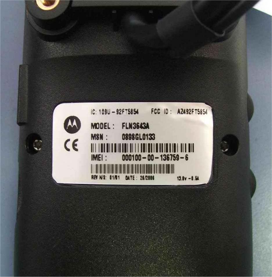
Click to zoom
Application Details
- Equipment Class
- TNB - Licensed Non-Broadcast Station Transmitter
- Date of Grant
- Jul 31, 2006
- Application Purpose
- Original Equipment
- Date of Application
- Jul 31, 2006
- Equipment Note
- SPIRIT iDEN M710
- Frequency Range
- 896.00000000 - 901.00000000
- Company
- Motorola Solutions, Inc.
- Country
- United States
Documents & Files
Document Text
Text extracted from the exhibit documents filed with the FCC. Open a document above to read the original.
Users Manual
Motorola Digital Multi-service Data-capable Car Phone M710 User's Guide IMPORTANT NOTICE: PLEASE READ PRIOR TO USING YOUR PHONE The SIM card provided in this kit is intended for use with the phone provided in this package. Loss of certain features will result when using a SIM card from one of the following models: i30sx, i35s, i50sx, i55sr, i58s, i60c, i80s, i85s, i88s, i90c, i95cl series, and the i2000 series. For more information on SIM card compatibility, go to www. motorola.com/iden/support. Defects or damage to your Motorola phone that result from the use of non-Motorola branded or certified Accessories, including but not limited to replacement housings and or other peripheral accessories, are excluded from warranty coverage. Please refer to the text of Motorola’s Limited One Year warranty located in this user’s guide for complete details. Dear customer, Motorola M710 Fixed Mobile Car Phone is uniquely designed for dedicated access to voice and data communication from within the vehicle environment. With its voice activation feature, enhanced display screen, well- spaced keypad and all round hands-free environment, the M710 is the more convenient way to talk and drive. Key Product Features • The M710 Voice Activated Dialing feature: Name dialing, which allows you to speak a voice tag that you have saved for a phonebook entry; and voice activated menu access, which allows you to browse to frequently used menu options by attaching voice tags to them. • High quality hands-free operation enables you to communicate in more convenient way while in the vehicle environment. • Enhanced color graphic display is designed for easy reading using 8 mm character height, with an adjustable backlight and contrast display setting. • A well-spaced keypad with large, illuminated tactile keys makes it easier for you to dial when mobile. • Enjoy the luxury of installing a single fixed mount unit that includes a display, keypad and radio, making the installation process easier and faster. • Value-added features including: Location Based Services via integrated AGPS; “Push-To” Features including Push-To- Talk, Push-To-Send Contacts and Push-To Send Pictures; and Multimedia services for downloadable media content * Various phone features are network dependant. ** Specifications subject to change without prior notice. Total Customer Satisfaction Absolute customer satisfaction is Motorola’s top priority. If you have a question, suggestion or any other issue concerning the Motorola phone, Motorola wants to hear from you. Motorola Australia Customer Care: 1300138 823 8am - 6pm Australia EST Motorola New Zealand Customer Care: 0508 668-676 10am - 8pm Motorola Canada Customer Care: 1-800-461-4575 Motorola USA Customer Care: 866-289-6866 Software Copyright Notice The Motorola products described in this manual, may include copyrighted Motorola and third party software stored in semiconductor memories or other media. Laws in the United States and other countries preserve for Motorola and third party software providers certain exclusive rights for copyrighted software, such as the exclusive rights to distribute or reproduce the copyrighted software. Accordingly, any copyrighted software contained in the Motorola products may not be modified, reverse- engineered, distributed, or reproduced in any manner to the extent allowed by law. Furthermore, the purchase of the Motorola products shall not be deemed to grant either directly or by implication, estoppel, or otherwise, any license under the copyrights, patents, or patent applications of Motorola or any third party software provider, except for the normal, non-exclusive, royalty-free license to use that arises by operation of law in the sale of a product. MOTOROLA, the Stylized M Logo and all other trademarks indicated as such herein are trademarks of Motorola,Inc.® Reg.U.S. Pat.&Tm.Off. TrueSync, Sidekick, Starfish and the Stylized Starfish Logo are registered trademarks of Starfish Software,Inc., a wholly owned independent subsidiary of Motorola,Inc. All other product or service names are the property of their respective owners. ©2006 Motorola,Inc. All rights reserved. Safety Information Important: Read this information before using your wireless mobile phone. Exposure to Radio Frequency Signal our wireless mobile telephone is a low power radio transmitter and receiver. When it is ON, it receives and also sends out radio frequency (RF) signals. Your Motorola wireless mobile telephone complies with the following RF energy exposure standards and guidelines: • United States Federal Communications Commission, Code of Federal Regulations; 47CFR part 2 sub-part J • American National Standards Institute (ANSI) / Institute of Electrical and Electronic Engineers (IEEE) C95. 1-1992 • Institute of Electrical and Electronic Engineers (IEEE) C95.1-1999 Edition • International Commission on Non-Ionizing Radiation Protection (ICNIRP) 1998 • Ministry of Health (Canada) Safety Code 6. Limits of Human Exposure to Radiofrequency Electromagnetic Fields in the Frequency Range from 3 kHz to 300 GHz, 1999 • Australian Communications Authority Radiocommunications (Electromagnetic Radiation - Human Exposure) Standard, 2003 • ANATEL, Brazil Regulatory Authority, Resolution No. 303 of July 2, 2002 “Regulation of the limitation of exposure to electrical, magnetic, and electromagnetic fields in the radio frequency range between 9KHz and 300 GHz.” and “Attachment to resolution # 303 from July 2, 2002” The design of your phone complies with these standards when used as described under "Phone Operation." Antenna Installation Guidelines Important: To meet the FCC's RF Exposure guidelines and satisfy the categorical exclusion requirements for mobile transmitters, the antenna must be installed so there is at least 30 cm of separation between the antenna and both the occupants of the vehicle and bystanders outside of the vehicle. Antenna Care Use only the supplied or an approved replacement antenna. Un…
Text truncated - open the document above for the full version.
Cover Letter(s)
FCC ID: AZ492FT5854 iDEN, Motorola Inc., 8000 W. Sunrise Blvd., Plantation, FL 33322 www.mot.com/iDEN Page: 13- 1 25 th July 2006 Authorization & Evaluation Division Federal Communications Commission Laboratory 7435 Oakland Mills Road Columbia, MD 21046 Subject: Application for Certification of transmitter with FCC ID: AZ492FT5854. Gentlemen; Motorola Inc., 8000 West Sunrise Boulevard, Fort Lauderdale, Florida 33322, herein submits its application for Certification of the transmitter with FCC ID: AZ492FT5854. This variable output power (0.062 to 490 milliwatt) transmitter is part of a handheld transceiver used in a SMR and EA SMR trunking system operating in the United States 806-821/851-866MHz and 896-901/935-940 MHz frequency band. Certification is sought for this transceiver, and performance data is provided for that purpose. Motorola Inc., 8000 West Sunrise Boulevard, Fort Lauderdale, Florida 33322, herein submits its application for Certification of the transmitter with FCC ID AZ489FT5854. This variable output power (490 and to 427 milliWatt) transmitter is part of a mobile transceiver used in a SMR and EA SMR trunking system operating in the United States 806-821/851-866MHz frequency band. The first transceiver is of the receive-first type described in International Telecommunications Union Recommendation ITU-R M.1221 entitled Technical And Operational Requirements For Cellular Multimode Mobile Radio Stations. It must first find, acquire and lock onto a control channel from a predefined set of control channel frequencies assigned to a companion Authorized base station (e.g. – FCC ID: AZ492FT5854). Transmission is not possible until lock to a base station control channel has been achieved, then transmission is limited to digitally modulated service request bursts on the reverse control channel. Upon recognition of a proper request, the control channel base station transmitter will then assign the transceiver a traffic channel for transmission of digital voice or circuit-switched data from the set of frequencies for which the trunking system is licensed. Attached Exhibit 12 provides additional descriptive details. To facilitate global roaming it is kindly requested that a note be provided in the Grant for Equipment Authorization, which states that this ‘receive first’ type of equipment is compliant for transmitter operation over the broader range 806-825 MHz when used with a compatible Authorized Base Station. This will aid equipment authorization in foreign countries, which accept a United States FCC Grant for Equipment Authorization, yet not jeopardize United States public safety or cellular systems licensed to operate in the 821-825 MHz frequency band since no compatible base station may be authorized on those frequencies in the United States. It is also expected that this transceiver type will be marketed outside the United States and brought into the United States for itinerant “roaming” operation on compatible 806 - 821 MHz base stations located within the United States. Consequently, upon receipt of Authorization, only those units of this equipment type authorized for marketing in countries outside the United States will also bear a label with the specified FCC identifier. FCC ID: AZ492FT5854 iDEN, Motorola Inc., 8000 W. Sunrise Blvd., Plantation, FL 33322 www.mot.com/iDEN Page: 13- 2 In accordance with 47 CFR 2.1093(c) this transmitter may be used in “covered” SMR service so it has been subjected to routine environmental evaluation for RF exposure and found to be compliant with the limits specified in 47 CFR 2.1093(d)(2). The subject transmitter complies with 47 CFR 90.203 of the rules in that the operator cannot directly program transmit frequencies using only the unit's normally accessible external controls. Enclosed is a complete Certification Application comprised of 12 Exhibits. Contact me at (954) 723- 5793 if you require any additional information. Sincerely, /s/ Mike Ramnath (signed) Manager, Regulatory Compliance Email: [email protected]
Cover Letter(s)
8000 West Sunrise Boulevard, Fort Lauderdale, Florida 33322. USA CONFIDENTIALITY REQUESTED Date: 25 th July 2006 Authorization & Evaluation Division Federal Communications Commission Laboratory 7435 Oakland Mills Road Columbia, MD 21046 Subject: Confidentiality Request for Transmitter with FCC ID: AZ492FT5854 Model Number: F321501GNAA Sir or Madam: Motorola is requesting that Exhibit 4 (Circuit Descriptions), Exhibit 5 (Schematic Diagrams), Exhibit 10 (Parts List and Tune-Up Procedures), and Exhibit 12 (Operational Description) not be made routinely available for public inspection. Motorola considers the information in these exhibits to be classified as trade secrets, pursuant to 47 CFR Section 0.457(d) and Section 552(b)(4) of the Freedom of Information Act. We are also requesting that the FCC mark Exhibit 3 (External Photos) and Exhibit 9 (Internal Photos) as Temporary Confidentiality as outlined in Public Notice DA 04-1705, dated June 15, 2004. This provision will give Motorola temporary confidentiality prior to product launch. Please mark Exhibits 4, 5, 10, and 12 as “Confidential” And Exhibit 3 and 9 as “Temporary Confidential”. Please contact me if you require any additional information. Sincerely, /s/ Mike Ramnath (signed) Manager, Regulatory Compliance Tel: (954) 723-5793 E-mail: [email protected] EXHIBIT 13b
External Photos
Applicant: Motorola Inc. FCC ID: AZ492FT5854 Exhibit 3 Page 1 of 5 EXHIBIT 3 EXTERNAL PHOTOGRAPHS This document contains 4 photographs Applicant: Motorola Inc. FCC ID: AZ492FT5854 Exhibit 3 Page 2 of 5 Photograph No.1 M710 phone front view Applicant: Motorola Inc. FCC ID: AZ492FT5854 Exhibit 3 Page 3 of 5 Photograph No.2 M710 phone rear view Applicant: Motorola Inc. FCC ID: AZ492FT5854 Exhibit 3 Page 4 of 5 Photograph No.3 M710 phone rear view Applicant: Motorola Inc. FCC ID: AZ492FT5854 Exhibit 3 Page 5 of 5 Photograph No4 M710 phone rear view without cover
ID Label/Location Info
Applicant: Motorola, Inc. FCC ID: AZ492FT5854 Exhibit 1 EXHIBIT 1: FCC IDENTIFICATION LABEL Required Under Section: 47 CFR 2.1033(b)(7), 2.1033(c) 11 FCC ID: AZ492FT5854 Identifier label for the model: FLN3643A Applicant: Motorola, Inc. FCC ID: AZ492FT5854 Exhibit 1 Label Location: Back side of the car phone Applicant: Motorola, Inc. FCC ID: AZ492FT5854 Exhibit 1 EXHIBIT 1A: General Information --- 47 CFR 2.1031. 1A.1. Production Plans -- Pursuant 47 CFR 2.1031 Quantity production is planned. 1A.2. Application References Reference is made to the following Motorola "Application References" 1. Part 90 Private Land Mobile Radio Devices and their application 1A.3. Data Submittal Procedure Data located in Exhibit 6 is supplied in accordance with Part 2, Subpart J and Part 90 of the Commissions ’ rules and will be submitted electronically.
Internal Photos
Applicant: Motorola Inc. FCC ID:AZ492FT5854 Exhibit 9 Page 1 of 14 EXHIBIT 9 INTERNAL PHOTOGRAPHS This document contains 13 photographs Applicant: Motorola Inc. FCC ID:AZ492FT5854 Exhibit 9 Page 2 of 14 Photograph No.1 M710 phone internal view Applicant: Motorola Inc. FCC ID:AZ492FT5854 Exhibit 9 Page 3 of 14 Photograph No.2 M710 phone internal view Applicant: Motorola Inc. FCC ID:AZ492FT5854 Exhibit 9 Page 4 of 14 Photograph No.3 M710 phone PCB with radio module Applicant: Motorola Inc. FCC ID:AZ492FT5854 Exhibit 9 Page 5 of 14 Photograph No.4 M710 main PCB with radio module removed Applicant: Motorola Inc. FCC ID:AZ492FT5854 Exhibit 9 Page 6 of 14 Photograph No.5 Back side view of radio PCB Applicant: Motorola Inc. FCC ID:AZ492FT5854 Exhibit 9 Page 7 of 14 Photograph No.6 Back side view of radio PCB without shields Applicant: Motorola Inc. FCC ID:AZ492FT5854 Exhibit 9 Page 8 of 14 Photograph No.7 Radio PCB front view Applicant: Motorola Inc. FCC ID:AZ492FT5854 Exhibit 9 Page 9 of 14 Photograph No.8 Radio PCB front view Applicant: Motorola Inc. FCC ID:AZ492FT5854 Exhibit 9 Page 10 of 14 Photograph No.9 Main PCB front view Applicant: Motorola Inc. FCC ID:AZ492FT5854 Exhibit 9 Page 11 of 14 Photograph No.10 Main PCB front view Applicant: Motorola Inc. FCC ID:AZ492FT5854 Exhibit 9 Page 12 of 14 Photograph No.11 Main PCB second side view Applicant: Motorola Inc. FCC ID:AZ492FT5854 Exhibit 9 Page 13 of 14 Photograph No.12 Main PCB second side view without shields Applicant: Motorola Inc. FCC ID:AZ492FT5854 Exhibit 9 Page 14 of 14 Photograph No.13 PCB close view
Internal Photos
Applicant: Motorola Inc. FCC ID:AZ492FT5854 Exhibit 9 Page 1 of 14 EXHIBIT 9 INTERNAL PHOTOGRAPHS This document contains 13 photographs Applicant: Motorola Inc. FCC ID:AZ492FT5854 Exhibit 9 Page 2 of 14 Photograph No.1 M710 phone internal view Applicant: Motorola Inc. FCC ID:AZ492FT5854 Exhibit 9 Page 3 of 14 Photograph No.2 M710 phone internal view Applicant: Motorola Inc. FCC ID:AZ492FT5854 Exhibit 9 Page 4 of 14 Photograph No.3 M710 phone PCB with radio module Applicant: Motorola Inc. FCC ID:AZ492FT5854 Exhibit 9 Page 5 of 14 Photograph No.4 M710 main PCB with radio module removed Applicant: Motorola Inc. FCC ID:AZ492FT5854 Exhibit 9 Page 6 of 14 Photograph No.5 Back side view of radio PCB Applicant: Motorola Inc. FCC ID:AZ492FT5854 Exhibit 9 Page 7 of 14 Photograph No.6 Back side view of radio PCB without shields
RF Exposure Info
FCC ID: AZ492FT5854 SR4234 Page 1 of 4 Certificate Number: 1651-04 FCC ID: AZ492FT5854 DECLARATION OF COMPLIANCE MPE ASSESSMENT Network & Enterprise Mobility Solutions EME Test Laboratory 8000 West Sunrise Blvd Fort Lauderdale, FL. 33322 Date of Report: July 27, 2006 Report Revision: Rev. O Report ID: FCC MPE rpt_M710_Rev O_060727 SR4234 Responsible Engineer: Michael Sailsman (Sr. Staff EME Engineer) Date/s Tested: N/A (MPE-Numerical assessment) Manufacturer/Location: Motorola, Israel South Date submitted for test: 7/18/06 DUT Description: Car Phone for iDEN 800/900MHz; Test TX mode(s): N/A (MPE-Numerical assessment) Max. Power output: 489.78mW for 800MHz; 426.58mW for 900MHz TX Frequency Bands: 806-825MHz and 896-901 MHz Signaling type: iDEN QPSK, 16QAM, 64QAM Model(s) Tested: F321501GNAA (MPE-Numerical assessment) Model(s) Certified: F321501GNAA Serial Number(s): NA Classification: General Population/Uncontrolled Rule Part(s): 90 Based on the information provided herein, the undersigned certifies that when used as stated in the operating instructions supplied, said product complies with the FCC standard 47 CFR §1.1310. This report shall not be reproduced without written approval from an officially designated representative of the Motorola EME Laboratory. Mark Douglas signature on file for Ken Enger Ken Enger GEMS EME Lab Senior Resource Manager, Laboratory Director, Approval Date: 7/27/06 Certification Date: 7/27/06 Certification No.: L1060712 FCC ID: AZ492FT5854 SR4234 Page 2 of 4 TABLE OF CONTENTS 1.0 Product and System Description 2.0 Evaluation methods 3.0 MPE Analysis 4.0 Conclusion REVISION HISTORY Date Revision Comments 7/27/06 O Original release FCC ID: AZ492FT5854 SR4234 Page 3 of 4 1.0 Product and System Description The M710 model F321501GNAA FCC ID AZ492FT5854 is a fixed mobile car phone designed for dedicated access to voice and data communication from within a vehicle. This device incorporates enhanced display, well spaced keypad with all around hands-free environment and voice activation features. This device operates in the iDEN 806-825MHz and 896-901MHz bands. The maximum operational duty cycle is 67.5%. The maximum conducted output power is 489.78mW (800MHz) and 426.58mW (900MHz) as defined by the upper limit of the production line final test station. Motorola does not offer an antenna for this device and the recommended maximum antenna gain to be used for this device is +6dBi. The User manual for this product instructs the Systems Integrator to assure that transmission occurs only when the operator and nearby persons are at least 30 cm from the antenna. Therefore, this product will be evaluated as a mobile device per 47 CFR §1.1310 titled “Radio frequency radiation exposure limits”, generally referred to as Maximum Permissible Exposure (MPE) limits, for General Population. 2.0 Evaluation methods: MPE numerical assessment is used to evaluate the RF exposure of this M710 car phone based on a maximum antenna gain of 6dBi for both bands of operation According to OET Bulletin 65 Edition 97-01 Section 2, calculations can be made to predict RF field strength and power density levels around typical RF sources. For example, in the case of a single radiating antenna, a prediction for power density in the far-field of the antenna can be made by use of the general Equations (3) or (4) below. These equations are generally accurate in the far-field of an antenna but will over-predict power density in the near field, where they could be used for making a "worst case" or conservative prediction. 2 4R PG S π = (3) Where: S = power density (mW/cm^2) P = power input to the antenna (mW) G = power gain of the antenna in the direction of interest relative to an isotropic radiator R = distance to the center of radiation of the antenna (cm) Or 2 4R EIRP S π = (4) Where: EIRP = equivalent (or effective) isotropically radiated power FCC ID: AZ492FT5854 SR4234 Page 4 of 4 3.0 MPE Analysis: Specification Limit - FCC Max Permissible Exposure (mW/cm2) Max Antenna Gain Max power (W) Frequency Range (MHz) Distance (cm) Radiated power density (mW/cm2) (*)Radiated power density perfect reflecting ground plane (mW/cm2) Uncontrolled Controlled 6 dBi 0.4898 806-825 30 0.116 0.466 0.54 2.69 6 dBi 0.4266 896-902 30 0.101 0.405 0.60 2.99 Note: (*) A perfect reflecting ground plane, in-phase field combination is assumed, resulting in a four-fold power density increase. 4.0 Conclusion: The MPE results for M710 per the assessment above are compliant to the FCC General population/Uncontrolled exposure limits of f/1500 per 47 CFR §1.1310 titled “Radio frequency radiation exposure limits”.
Test Report
Hermon Laboratories Ltd. P.O.Box 23, Binyamina 30500, Israel Tel. +972 4628 8001 Fax. +972 4628 8277 E-mail: [email protected] Page 1 of 158 Report ID: MOTRAD_FCC.17112.doc Date of Issue: 7/6/2006 Electrical TEST REPORT ACCORDING TO: FCC CFR 47 PART 90 SUBPART S and PART 15 SUBPART B FOR: Motorola Israel Ltd. Car phone Product name: Spirit iDEN Trade name: M710 Model: F321501GNAA FCC ID:AZ492FT5854 IC:109U-92 FT5854 This report is in conformity with ISO/ IEC 17025. The A2LA logo endorsement applies only to the test methods and the standards that are listed in the scope of Hermon Laboratories accreditation. The test results relate only to the items tested. This test report shall not be reproduced in any form except in full with the written approval of Hermon Laboratories Ltd. Report ID: MOTRAD_FCC.17112.doc Date of Issue: 7/6/2006 Page 2 of 158 Table of contents 1 Applicant information..................................................................................................................................................... 3 2 Equipment under test attributes .................................................................................................................................... 3 3 Manufacturer information .............................................................................................................................................. 3 4 Test details.................................................................................................................................................................... 3 5 Tests summary.............................................................................................................................................................. 4 6 EUT description............................................................................................................................................................. 5 6.1 General information....................................................................................................................................................... 5 6.2 Ports and lines .............................................................................................................................................................. 5 6.3 Support and test equipment .......................................................................................................................................... 5 6.4 Changes made in the EUT ............................................................................................................................................ 5 6.5 Test configuration.......................................................................................................................................................... 6 6.6 Transmitter characteristics ............................................................................................................................................ 7 7 Transmitter tests according to 47CFR part 90 requirements......................................................................................... 8 7.1 Peak output power test.................................................................................................................................................. 8 7.2 Occupied bandwidth test ............................................................................................................................................. 12 7.3 Emission mask test ..................................................................................................................................................... 20 7.4 Radiated spurious emission measurements................................................................................................................ 21 7.5 Spurious emissions at RF antenna connector test ...................................................................................................... 52 7.6 Frequency stability test................................................................................................................................................ 78 8 Emissions tests according to 47CFR part 15 subpart B requirements ........................................................................ 82 8.1 Conducted emissions .................................................................................................................................................. 82 8.2 Radiated emission measurements .............................................................................................................................. 86 9 APPENDIX A Test equipment and ancillaries used for tests....................................................................................... 91 10 APPENDIX B Measurement uncertainties................................................................................................................... 93 11 APPENDIX C Test facility description ......................................................................................................................... 94 12 APPENDIX D Specification references ....................................................................................................................... 94 13 APPENDIX E Abbreviations and acronyms................................................................................................................. 95 14 APPENDIX F Test equipment correction factors ......................................................................................................... 96 Report ID: MOTRAD_FCC.17112.doc Date of Issue: 7/6/2006 Page 3 of 158 1 Applicant information Client name: Motorola Israel Ltd. Address: 3 Kremenetski street, P.O.B. 25016, 67899 Tel Aviv, Israel Telephone: +972 3565 8888 Fax: +972 3565 8888 E-mail: [email protected] Contact name: Mr. Alex Babaladze 2 Equipment under test attributes Product name: Car phone Product name: Spirit iDEN Trade name: M710 EUT model: FLN364…
Text truncated - open the document above for the full version.
Test Setup Photos
Applicant: Motorola Inc. FCC ID:AZ492FT5854 Exhibit 7 Page 1 of 10 SETUP PHOTOGRAPHS This document contains 9 photographs Applicant: Motorola Inc. FCC ID:AZ492FT5854 Exhibit 7 Page 2 of 10 Photograph No.1 RF output power measurement setup Applicant: Motorola Inc. FCC ID:AZ492FT5854 Exhibit 7 Page 3 of 10 Photograph No.2 Occupied bandwidth, spurious emission measurement setup Applicant: Motorola Inc. FCC ID:AZ492FT5854 Exhibit 7 Page 4 of 10 Photograph No.3 Spurious emissions measurement setup in the anechoic chamber with loop antenna Applicant: Motorola Inc. FCC ID:AZ492FT5854 Exhibit 7 Page 5 of 10 Photograph No.4 Spurious emissions measurement setup in the anechoic chamber with biconilog antenna Applicant: Motorola Inc. FCC ID:AZ492FT5854 Exhibit 7 Page 6 of 10 Photograph No.5 Radiated emissions measurement setup in the anechoic chamber Applicant: Motorola Inc. FCC ID:AZ492FT5854 Exhibit 7 Page 7 of 10 Photograph No.6 Spurious emission field strength measurements above 1000 MHz at the OATS Applicant: Motorola Inc. FCC ID:AZ492FT5854 Exhibit 7 Page 8 of 10 Photograph No.7 Spurious emission field strength measurements at the OATS, EUT close view Applicant: Motorola Inc. FCC ID:AZ492FT5854 Exhibit 7 Page 9 of 10 Photograph No.8 Frequency stability measurements setup Applicant: Motorola Inc. FCC ID:AZ492FT5854 Exhibit 7 Page 10 of 10 Photograph No.9 Conducted emission measurements on power lines setup
Contact Information
Applicant
Arine Lee(Certification Manager)
Test Firm
MotorolaWilliam Elliott
Technical Specifications
| # | Rule Parts | Frequency Range | Power Output | Emission | Tolerance |
|---|---|---|---|---|---|
| 8 | 9 | 896 MHz - 901 MHz | 427.00 mW | 93K3D7D | 0.5 ppm |
Other Applications from Motorola Solutions, Inc.

AZ489FT4980
Sep 08, 2026Portable two way radio
Equipment Class
TNF - Licensed Non-Broadcast Transmitter Held to FaceAZ489FT4981
Aug 14, 2026Handheld Portable - TANAPA BPR 45 400-470 MHZ 4W NKP
Equipment Class
TNF - Licensed Non-Broadcast Transmitter Held to Face
AZ489FT7187
Jul 13, 2026Portable 2-Way Radio with Bluetooth, Bluetooth LE, WIFI 2.4GHz, WIFI 5GHz, LTE
Equipment Class
DSS - Part 15 Spread Spectrum TransmitterAZ499FT6031
May 11, 2026Operation Critical Wireless Earpiece PTT
Equipment Class
DSS - Part 15 Spread Spectrum Transmitter
AZ499FT5879
Dec 19, 20252-way Portable Radio with BT, BTLE, WIFI, NFC and LTE
Equipment Class
DSS - Part 15 Spread Spectrum Transmitter