AZ492FT71182-Way Mobile Radio (with Bluetooth, Bluetooth LE and WIFI)
Motorola Solutions, Inc.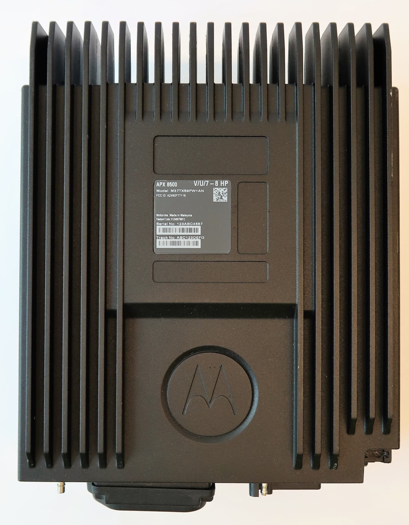
Click to zoom
Application Details
- Equipment Class
- DSS - Part 15 Spread Spectrum Transmitter
- Date of Grant
- Jun 11, 2020
- Application Purpose
- Original Equipment
- Date of Application
- Jun 11, 2020
- Equipment Note
- 2-Way Mobile Radio (with Bluetooth, Bluetooth LE and WIFI)
- Frequency Range
- 2402.00000000 - 2480.00000000
- Company
- Motorola Solutions, Inc.
- Country
- United States
Documents & Files
Document Text
Text extracted from the exhibit documents filed with the FCC. Open a document above to read the original.
Users Manual
Contents Declaration of Conformity.........................8 Important Safety Information........10 Notice to Users (FCC and Industry Canada)........................ 11 Software Version........................................... 11 Consignes de sécurité importantes.................................12 Avis aux utilisateurs (FCC et Industrie Canada)....................... 13 Version logicielle............................................13 Computer Software Copyrights....14 Documentation Copyrights........... 15 Disclaimer.......................................16 Getting Started............................... 17 How to Use This Guide..................................17 Notations Used in This Manual......................17 Additional Performance Enhancement.......... 17 ASTRO 25 Enhanced Data.................18 Dynamic System Resilience (DSR).... 18 CrossTalk Prevention..........................18 Encrypted Integrated Data (EID).........18 SecureNet........................................... 18 P25 Digital Vehicular Repeater System (DVRS)............................. 18 Conventional Talkgroup and Radio Scan Enhancements......................18 What Your Dealer/System Administrator Can Tell You............................................. 19 Contents 1 English Preparing Your Radio for Use.......20 Turning On the Radio....................................20 Adjusting the Volume.....................................21 Validating Compatibility During Power Up..... 21 Identifying Radio Controls............ 22 Radio Parts and Controls.............................. 22 Control Head and Microphone............ 22 Programmable Features................................ 23 Assignable Radio Functions............... 23 Assignable Settings or Utility Functions....................................... 26 Accessing the Preprogrammed Functions.....26 Menu Select Buttons...........................27 Advance Programmable Buttons........ 27 Home Button....................................... 28 4-Way Navigation Button.................... 28 Data Feature Button........................... 28 Volume Knob...................................... 29 Using the Mode Knob......................... 29 Keypad.......................................................... 29 Keypad Characters – Uppercase Mode.............................................. 29 Keypad Characters – Lowercase Mode..............................................30 Keypad Characters – Numeric Mode.............................................. 32 Keypad Characters – Hexadecimal Mode.............................................. 33 Push-To-Talk (PTT) Button............................34 Identifying Status Indicators.........35 Status Icons................................................... 35 Text Messaging Service (TMS) Indicators.....38 TMS Status Icons................................38 TMS Menu Options............................. 39 LED Indicator................................................. 40 Intelligent Lighting Indicators ........................ 41 Alert Tones.................................................... 43 General Radio Operation...............46 Selecting a Zone............................................46 Selecting a Radio Channel............................ 46 Selecting a Channel via Channel Search Button....................................................... 47 Mode Select Feature..................................... 47 Contents 2 English Saving a Zone and a Channel to a Softkey...........................................48 Saving a Zone and a Channel to a Button............................................ 48 Receiving and Responding to a Radio Call... 49 Receiving and Responding to a Talkgroup Call................................49 Receiving and Responding to a Private Call (Trunking Only)...........50 Receiving and Responding to a Telephone Call (Trunking Only)..... 50 Methods to Make a Radio Call.......................51 Making a Talkgroup Call..................... 51 Making a Private Call (Trunking Only).............................................. 52 Making a Telephone Call (Trunking Only).............................................. 53 Switching Between Repeater or Direct Operation Button...................................... 54 Monitor Feature............................................. 54 Monitoring a Channel..........................54 Monitoring Conventional Mode........... 55 Advanced Features........................56 Advanced Call Features................................ 56 Calling a Phone Not in the List............56 Selective Call (ASTRO Conventional Only)........................56 Talkgroup Call Feature (Conventional Operation Only)...... 57 Sending a Status Call......................... 58 Responding to the Dynamic Regrouping Feature (Trunking Only).............................................. 59 Dynamic Zone Programming (DZP)....60 Multiple Control Head Features..................... 62 Setting the ID of the Initial Control Head.............................................. 62 All Active Mode................................... 63 Activating and Deactivating Intercom in All Active Mode........... 63 One Active Mode................................ 64 Contacts........................................................ 65 Making a Private Call from Contacts...66 Adding a New Contact Entry...............67 Deleting a Contact Entry..................... 67 Adding a Contact to a Call List............68 Methods of Contact Editing in a Call List.......................................... 68 Scan Lists...................................................... 70 Viewing a Scan List.............................70 Editing the Scan List........................... 70 Contents 3 English Changing the Scan List Status............71 Viewing and Changing the Priority Status.............................................72 Scan.............................................................. 72 Turning Scan On or Off.......................72 Turning Scan O…
Text truncated - open the document above for the full version.
Users Manual
English mASTRO ® APX™ O5 Control Head Mobile RadioQuick Reference Card RF Energy Exposure and Product Safety Guide for Mobile Two-Way Radios ATTENTION! This radio is restricted to Occupational use only. Before using the radio, read the RF Energy Exposure and Product Safety Guide for Mobile Two-Way Radios which contains important operating instructions for safe usage and RF energy awareness and control for Compliance with applicable standards and Regulations. Radio Controls Radio On/OffAdjusting VolumeSelecting a ZoneSelecting a Channel Receiving and TransmittingSending an Emergency Alarm To exit emergency at any time, press and hold the Emergency button. Volume Knob Accessory Port (Microphone) Menu Select Button Menu Entries LED Indicators Dim Button Home Button Navigation Button Power On/Off Button Indicators Mode Knob Orange Button Press the Power On/Off button to toggle the power on or off.* * The duration that user must press and hold the Power On/Off button to turn off the radio is programmable by a qualified radio technician. Turn the Volume Knob clockwise to increase volume or counterclockwise to decrease the volume. 1 > or < to ZONE . 2 > or < button until the desired zone is displayed. 3 Press H or the PTT button to confirm the selected zone number. 4 Press the PTT button to begin transmitting on the displayed zone channel. 1 Press and hold > to scroll to CHAN and press the Menu Select button directly below CHAN . The display shows the current zone and channel. 2 Rotate the Mode knob to the desired channel. 3 Press H or the PTT button to confirm the channel. 4 Press the PTT button to transmit on the displayed zone channel. 1 Take the microphone off hook. 2 Select zone/channel. 3 Listen for a transmission. ORTurn the Volume Knob. OR> or < to MON then press the Menu Select button directly below MON and listen for activity. 4 Adjust volume, if necessary. 5 Press the PTT button to transmit; release to receive. 1 Press the Emergency button. A tone sounds and the display alternates EMERGENCY and the home display. 2 A dispatcher acknowledgment ACK RECEIVED display follows.AND, Trunking Only:A high-pitched tone indicates that the alarm has been received by the trunked system’s central controller. 3 Press and hold the emergency button or the PTT button to return to normal operation. *PMLN5592G* PMLN5592G MOTOROLA, MOTO, MOTOROLA SOLUTIONS and the Stylized M logo are trademarks or registered trademarks of Motorola Trademark Holdings, LLC and are used under license. All other trademarks are the property of their respective owners.© 2009–2011, 2013, 2015 by Motorola Solutions, Inc. All Rights Reserved. 06/151303 East Algonquin Road, Schaumburg, Illinois 60196, U.S.A. English Sending an Emergency Call (Trunking Only) To exit emergency at any time, press and hold the Emergency button. Sending a Silent Emergency Alarm If silent emergency alarm is used with emergency call, pressing the PTT button exits the silent mode and initiates the emergency call. Display Status Icons 1 Press Emergency button. 2 A tone sounds and the display alternates EMERGENCY and the home display. ORA talk prohibited tone sounds when the selected channel does not support emergency. 3 Press and hold the PTT button. Speak clearly into the microphone. 4 Release the PTT to end the transmission. 1 Press the preprogrammed Emergency button to activate the silent alarm feature. 2 The display does not change; the LED does not light up, and there is no tone. Receiving a call or data.Transmitting a call or data.The more stripes, the stronger the signal strength for the current site (trunking only). u t V Direct radio-to-radio communication or communication through a repeater.On = Direct Off = Repeater This channel is being monitored.Voice muting the affiliated trunking talkgroup or selected conventional channel.On = Enabled Off = Disabled L = Radio is set at Low power. H = Radio is set at High power. Scanning a scan list.Blinking dot = Detects activity on the Priority-One Channel during scan. Steady dot = Detects activity on the Priority- Two Channel during scan. The vote scan feature is enabled. O M K H OR . i j k On = Secure operation. Off = Clear operation. Blinking = Receiving an encrypted voice call. On = AES Secure operation. Off = Clear operation. Blinking = Receiving an encrypted voice call. On = Location feature enabled, and location signal available. Off = Location feature disabled. Blinking = Location feature enabled, but location signal unavailable. On = User is currently associated with the radio. Off = User is currently not associated with the radio. Blinking = Device registration or user registration with the server failed due to an invalid username or pin. Data activity is present.Indicates that the text entry is currently in hexadecimal mode. m l G no { Menu Navigation < or > to Menu Entry. g directly below Menu Entry to select. H to exit. < or > to scroll through sub-list. g directly below Menu Entry to select.
Users Manual
-i Page APX™ TWO-WAY RADIOS APX 8500 MOBILE RADIO INSTALLATION MANUAL Draft 0 Draft i Foreword This manual covers the O2, O3, O5, O7 and O9 models of the ASTRO ® APX™ mobile radios. It includes all the information necessary to install high and mid power radios and configure radio installation inside vehicles. For details on radio operation or component-level troubleshooting, refer to the applicable manuals available separately. A list of related publications is provided in the section “Related Publications” RF Energy Exposure and Product Safety Guide for Mobile Two-way Radios See “Installation Requirements for Compliance with Radio Frequency (RF) Energy Exposure Safety Standards,”. Manual Revisions Changes which occur after this manual is printed are described in PMRs (Publication Manual Revisions). These PMRs provide complete replacement pages for all added, changed, and deleted items. To obtain PMRs, go to https://businessonline.motorolasolutions.com. Parts Ordering See Appendix A: Replacement Parts Ordering for information on how to obtain replacement parts. For part numbers, refer to the ASTRO APX Mobile Radio Basic Service Manual (Motorola Solutions publication). Computer Software Copyrights The Motorola Solutions products described in this manual may include copyrighted Motorola Solutions computer programs stored in semiconductor memories or other media. Laws in the United States and other countries preserve for Motorola Solutions certain exclusive rights for copyrighted computer programs, including, but not limited to, the exclusive right to copy or reproduce in any form the copyrighted computer program. Accordingly, any copyrighted Motorola Solutions computer programs contained in the Motorola Solutions products described in this manual may not be copied, reproduced, modified, reverse-engineered, or distributed in any manner without the express written permission of Motorola Solutions. Furthermore, the purchase of Motorola Solutions products shall not be deemed to grant either directly or by implication, estoppel, or otherwise, any license under the copyrights, patents or patent applications of Motorola Solutions, except for the normal non-exclusive license to use that arises by operation of law in the sale of a product. Document Copyrights No duplication or distribution of this document or any portion thereof shall take place without the express written permission of Motorola Solutions. No part of this manual may be reproduced, distributed, or transmitted in any form or by any means, electronic or mechanical, for any purpose without the express written permission of Motorola Solutions. Disclaimer The information in this document is carefully examined, and is believed to be entirely reliable. However, no responsibility is assumed for inaccuracies. Furthermore, Motorola Solutions reserves the right to make changes to any products herein to improve readability, function, or design. Motorola Solutions does not assume any liability arising out of the applications or use of any product or circuit described herein; nor does it cover any license under its patent rights nor the rights of others. Trademarks MOTOROLA, MOTO, MOTOROLA SOLUTIONS and the Stylized M logo are trademarks or registered trademarks of Motorola Trademark Holdings, LLC and are used under license. All other trademarks are the property of their respective owners. © 2018 by Motorola Solutions, Inc. All rights reserved. Draft ii Installation Requirements for Compliance with Radio Frequency (RF) Energy Exposure Safety Standards ATTENTION! This radio is intended for use in occupational/controlled conditions, where users have full knowledge of their exposure and can exercise control over their exposure to meet FCC limits. This radio device is NOT authorized for general population, consumer, or any other use. To ensure compliance to RF Energy Exposure Regulations: •Install only Motorola Solutions approved antennas and accessories •Be sure that antenna installation is per “Antenna Installation” of this manual •Be sure that Product Safety and RF Safety Booklet enclosed with this radio is available to the end user upon completion of the installation of this radio Before using this product, read the guide enclosed with your radio which contains important operating instructions for safe usage and RF energy awareness and control for compliance with applicable standards and regulations. For a list of Motorola Solutions-approved antennas and other accessories, visit the following web site which lists approved accessories for your radio model: http://www.motorolasolutions.com. Draft Table of Contents iii MN003109A01 Table of Contents Foreword ..........................................................................................................i RF Energy Exposure and Product Safety Guide for Mobile Two-way Radios..............................................i Manual Revisions .........................................................................................................................................i Parts Ordering ..............................................................................................................................................i Computer Software Copyrights ....................................................................................................................i Document Copyrights ...................................................................................................................................i Disclaimer.....................................................................................................................................................i Trademarks ..................................................................................................................................................i Installation Requirements for Compliance with Radio Frequency (RF) Energy Exposure Safety Standards .......................ii Mobile Radio Model Numbering Sc…
Text truncated - open the document above for the full version.
Users Manual
MN003109A01_aa 4-2Options and Accessories Installation Remote-Mount Accessory Installation 4.1.2Dash-Mount Horn and Lights (External Alarms) Relays NOTE:For installations that use the horn/lights option, select a suitable location for mounting (normally under the dash) and, referring to Figure 4-2, perform the following procedure: 1.Horn Relay – Connect the relay contacts across the horn ring switch, typically found in the steering column. Open the accessory cable connector and connect the two control wires (male pins) into locations 18 and 24 of the connector. 2.Lights Relay – Connect the relay across the head lamp ON/OFF switch, typically found in the steering column. Open the accessory cable connector and connect the two control wires (male pins) into locations 19 and 24 of the accessory connector. Figure 4-2. Horn/Light Wiring Diagram Figure 4-3. Radio MAP Connector 4.2Remote-Mount Accessory Installation Perform the following installation procedure: 1. Select an appropriate place to mount the option or accessory hardware. 2. Route the accessory-to-control head cables under floor coverings or behind panels so that the vehicle occupants do not snag or break the wires. 3. Attach wires from the accessory to the appropriate wire on the VIP cable (see Table 4-1 and Table 4-2). CONNECT ACROSS HORN RING SWITCH CONNECT ACROSS HEAD LAMP SWITCH SPST N.O. RELAY 12V COIL 12V COIL VIP OUT 1 SWB+ VIP OUT 2 SPST N.O. RELAY ACCESSORIES CONNECTOR PIN 18 PIN 24 PIN 19 SWB+ VIP OUT 2 (LIGHTS) VIP OUT 1 (HORN) 1 7 8 14 13 20 21 26 Draft MN003109A01_aa Options and Accessories Installation Remote-Mount Accessory Installation4-3 4.2.1Emergency Pushbutton or Footswitch Installation Mount the switch using the hardware that comes with the kit. Connect the button/switch wires to a ground pin and the emergency pin, removing the default jumper wire in the rear accessory cable. The button/switch shorts the pins when in-active. When the button/switch is pressed, its contact opens, the emergency path is un-ungrounded and pulled-high inside the radio transceiver, and detected by the processor. If an emergency accessory is used at either (or both) J2 connector and J626 connector, all jumper wires, shorting emergency to ground, must be removed so button/switch press can be detected. 4.2.2Horn (External Alarm) Relay Installation Mount the horn relay in a suitable location (normally under the dash). Connect the relay contacts across the horn ring switch, typically found in the steering column. Connect the two control wires to a SW B+ pin and a VIP OUT pin on the VIP connector. 4.2.3Lights (External Alarm) Relay Installation Mount the light relay in a suitable location (normally under the dash). Connect the relay contacts across the head lamp ON/OFF switch. Connect the two control wires to a SW B+ pin and a VIP OUT pin on the VIP connector. 4.2.4Gunlock Installation The O7 or O9 control head can program up to three gunlocks through the programmable buttons. You can set the time for the momentary trigger using the time-out trigger button. Connect the relay contacts across the gunlock switch to install the gunlock. Connect the two control wires to a SW B+ pin and a VIP OUT pin on the VIP connector. It is recommended to install a failsafe/redundant bypass switch for the gunlock. It is suggested to use a separate timer switch or a manual push-on button switch to activate the gunlock. Connect the switch from the supply to the gunlock directly, as shown in Figure 4-4. Place the manual button at a suitable and reachable location, yet not easily seen. The radio is sold with correct accessory cables and jumpers in order to have emergency de-activated by default, regardless of the setting in CPS. However, if cables are not used, or if jumpers are removed without replacing with an emergency accessory button/switch at one of the accessory ports, the radio power-up upon the application of A+. The display may not show an indication that the radio is on, and this can result in an incorrect operation of the radio as well as excessive current drain of the vehicle battery when the engine is off. ! C a u t i o n Draft MN003109A01_aa 4-4Options and Accessories Installation Remote-Mount Accessory Installation Figure 4-4. Gunlock Switch Redundancy Diagram - Mid Power VIP OUT GND GND Gunlock Redundancy Wiring Car Battery A+ into Transceiver VIP OUT pin from either J2 (Transceiver) or J400 (control head) Momentary or time-out bypass manual switch Relay and Diode for Activation of Gunlock Draft MN003109A01_aa Options and Accessories Installation Remote-Mount Accessory Installation4-5 Figure 4-5. Gunlock Switch Redundancy Diagram - High Power NOTE:Refer to section 4.3.1 for information related to wiring and activation of VIPOUTs The Y-cable KT000247A01 is primarily designed to allow for simultaneous operation of the Motorola Solutions Branded SB9600 siren and still retain duplicate access to all the MAP (J2) connector pins located on the APX 8500 remote TIB. Use of emergency accessories, speakers, programming cables, VIPS, and others are possible through the P3 connector of Y-cable KT000247A01. The 26pin connector P2 does not contain every signal from the legacy DB25 port, called J600 on the APX 7500. Therefore, some legacy functionality that is A+ is reduced with the APX 8500 remote mount configuration compared to the APX 7500 remote mount configuration. Draft MN003109A01_aa 4-6Options and Accessories Installation Remote-Mount Accessory Installation 4.2.5Horn-Ring Transfer Configure the Horn Relay for either Negative Contact or Positive Contact as shown in section 6.3 of the siren/PA manual (6881093C18). Program the designated VIP-OUT line for “Horn-Ring Transfer” and program the designated VIP-IN line for “Horn-Ring”. Figure 4-6 shows wiring diagrams for connecting the Horn-Ring through a transfer relay for both negative and positive ground systems. Refer to the siren/PA manual (6881093C18) for more information. Figure 4-6. Siren/PA Horn-Ring Co…
Text truncated - open the document above for the full version.
Users Manual
en-US es-LA fr-CA pt-BR RF Energy ExposureTraining and Product Safety Information for Mobile Two-Way Radios installed in Vehicles or as Fixed Site Control Stations Formation sur l’exposition aux RF et information sur la sécurité du produit pour radios bidirectionnelles mobiles installées dans des véhicules ou comme stations de contrôle à emplacements fixes Capacitación sobre la exposición a energía de radiofrecuencia e información de protección del producto para radios de dos vías móviles instalados en vehículos o como estaciones de control fijas Treinamento sobre a Exposição à Energia de RF e Informações de Segurança do Produto para Rádios Portáteis Bidirecionais Instalados em Veículos ou como Estações de Controle de Site Fixo Caution Before using this radio, read this booklet which contains important operating instructions. For information on product details, brochures, user manuals and approved accessories. Please refer to www.motorolasolutions.com. Compliance with RF Exposure Standards National and international regulations require manufacturers to comply with the RF energy exposure limits for mobile two-way radios before they can be marketed. Your Motorola Solutions two-way radio is designed, manufactured, and tested to comply with all applicable national and international regulations for human exposure to radio frequency electromagnetic energy. When two-way radios are used as a consequence of employment, applicable regulations may require users to be fully aware of and able to control their exposure to meet occupational requirements. RF Energy Exposure Awareness and Control Information and Operational Instructions for Occupational Use Notice: This radio is intended for use in occupational/controlled conditions where users are aware of their exposure and can exercise control over their exposure to meet the requirements in national and international regulations. This radio device is not authorized for general population, consumer use. For more information on what RF energy exposure is, and how to control your exposure to ensure compliance with established RF exposure limits, consult the following websites: •https://www.fcc.gov/ •https://www.osha.gov/ •https://osha.europa.eu/en •http://www.who.int/peh-emf/project/en/ For additional user training information on exposure requirements, consult the following websites: •https://www.motorolasolutions.com/en_us/about/company-overview/corporate- responsibility/governance-and-policies/wireless-communication-and-health- faqs.html •http://learning.motorolasolutions.com/ RF Exposure Compliance and Control Guidelines To control exposure to yourself and others, and to ensure compliance with the relevant RF exposure limits, always adhere to the following guidelines: English 1 • Do not remove any of the RF Exposure Labels if present from this device or its related accessories. • Attach these instructions to the device when you transfer it to other users. • Do not use this device if the operational requirements described herein are not met. Operating Instructions • Transmit no more than 50% of the time. To transmit (talk), press the Push-To- Talk (PTT) button. To receive calls, release the PTT button. Transmitting more than 50% of the time may cause RF exposure compliance requirements to be exceeded. • Transmit only when people (bystanders) outside the vehicle are at least at the recommended minimum lateral distance (as shown in Tables 1 and 2) away from the vehicle body. This separation will ensure that there is sufficient distance from a properly installed (according to the installation instructions) externally-mounted antenna to satisfy the relevant RF exposure limits. • To ensure continued compliance with applicable RF exposure limits, use only Motorola Solutions approved, supplied or replacement antennas, batteries, and accessories. • For a list of Motorola Solutions approved accessories please refer to your user manual or visit www.motorolasolutions.com Table 1 lists the recommended lateral distance for bystanders from the body of a vehicle (For example, truck, van, car, motorcycle) equipped with an approved, properly installed single-band mobile radio and associated antenna(s). These lateral distances, for single-band radios, depend on the radio rated power. Table 1: Rated Power of Vehicle-Installed Single-Band Mobile Radio and Recommended Minimum Lateral Distance from Vehicle Body Single-Band Mobile Radio Rated Power (see Notice) Minimum Lateral Distance of By- standers from Vehicle Body Less than 7 W8 in. (20 cm) 7 to 14 W1 ft (30 cm) 15 to 39 W2 ft (60 cm) 40 to 110 W3 ft (90 cm) Notice: If you are not sure of the rated power of your single-band radio, contact your Motorola Solutions representative or dealer and supply the radio model number found on the radio model label. If you cannot English 2 determine the rated power, then assure 3 ft (90 cm) separation for bystanders from the body of the vehicle. Table 2 lists the recommended lateral distance for bystanders from the body of a vehicle (For example, truck, van, car, motorcycle) equipped with an approved, properly installed multi-band mobile radio and associated antenna(s). These lateral distances, for multi-band radios, depend on whether the radio is installed on a motorcycle, or on other kinds of vehicles. Table 2: Rated Power of Vehicle-Installed Multi-Band Mobile Radio and Recommended Minimum Lateral Distance from Vehicle Body Type of Vehicle Minimum Lateral Distance of By- standers from Vehicle Body Motorcycle2 ft (60 cm) Other vehicles3 ft (90 cm) Mobile Antenna Installation Guidelines • Make sure to follow the antenna installation guidelines that are provided in this mobile radio installation manual. • Use only Motorola Solutions approved supplied antenna, or a Motorola Solutions approved replacement antenna. Unauthorized antennas, modifications, or attachments could damage the radio and may result in non-compliance with RF Safety Standards. Guidelines and Operating Instructions fo…
Text truncated - open the document above for the full version.
Attestation Statements
Applicant: Motorola Solutions Inc. FCC ID: AZ492FT7118 EXHIBIT 2 SHEET 1 OF 2 EXHIBIT 2 Statement of Certification (Pursuant to FCC Part 2.907 and 2.908) 2.1 Statement of Certification Transceiver type described herein (AZ492FT7118) is in compliance with all applicable parts of the FCC rules. This device is P25 Compliant as well which meets FCC Part 90.548, as declared in exhibit 12. Each unit manufactured, imported, or marketed will conform to the samples tested herein, within the statistical variations that can be expected due to high volume production and test measurement error. NAME: Brandon Hammel SIGNATURE: DATE: 12/3/19 TITLE: Electrical Engineer Applicant: Motorola Solutions Inc. FCC ID: AZ492FT7118 EXHIBIT 2 SHEET 2 OF 2 2.2 Attestation Statement (Equipment Class DTS and DSS – Bluetooth/WiFi) This device contains an embedded Bluetooth device and WiFi device that are compliant with the applicable FCC Part 15C and FCC Part 15E regulations. Part 15.247 (a)(1) • The hopping sequence must be pseudo rando…
Text truncated - open the document above for the full version.
Contact Information
Applicant
Deanna Zakharia(Regulatory Compliance Manager)
Test Firm
Bureau Veritas CPS (H.K.) Ltd., Taoyuan BranchRichard Chen
Technical Specifications
| # | Rule Parts | Frequency Range | Power Output |
|---|---|---|---|
| 1 | 15C | 2.40 GHz - 2.48 GHz | 9.30 mW |
Other Applications from Motorola Solutions, Inc.

AZ489FT4980
Sep 08, 2026Portable two way radio
Equipment Class
TNF - Licensed Non-Broadcast Transmitter Held to FaceAZ489FT4981
Aug 14, 2026Handheld Portable - TANAPA BPR 45 400-470 MHZ 4W NKP
Equipment Class
TNF - Licensed Non-Broadcast Transmitter Held to Face
AZ489FT7187
Jul 13, 2026Portable 2-Way Radio with Bluetooth, Bluetooth LE, WIFI 2.4GHz, WIFI 5GHz, LTE
Equipment Class
DSS - Part 15 Spread Spectrum TransmitterAZ499FT6031
May 11, 2026Operation Critical Wireless Earpiece PTT
Equipment Class
DSS - Part 15 Spread Spectrum Transmitter
AZ499FT5879
Dec 19, 20252-way Portable Radio with BT, BTLE, WIFI, NFC and LTE
Equipment Class
DSS - Part 15 Spread Spectrum Transmitter