AZ492FT7140Mobile 2 Way Radio
Motorola Solutions, Inc.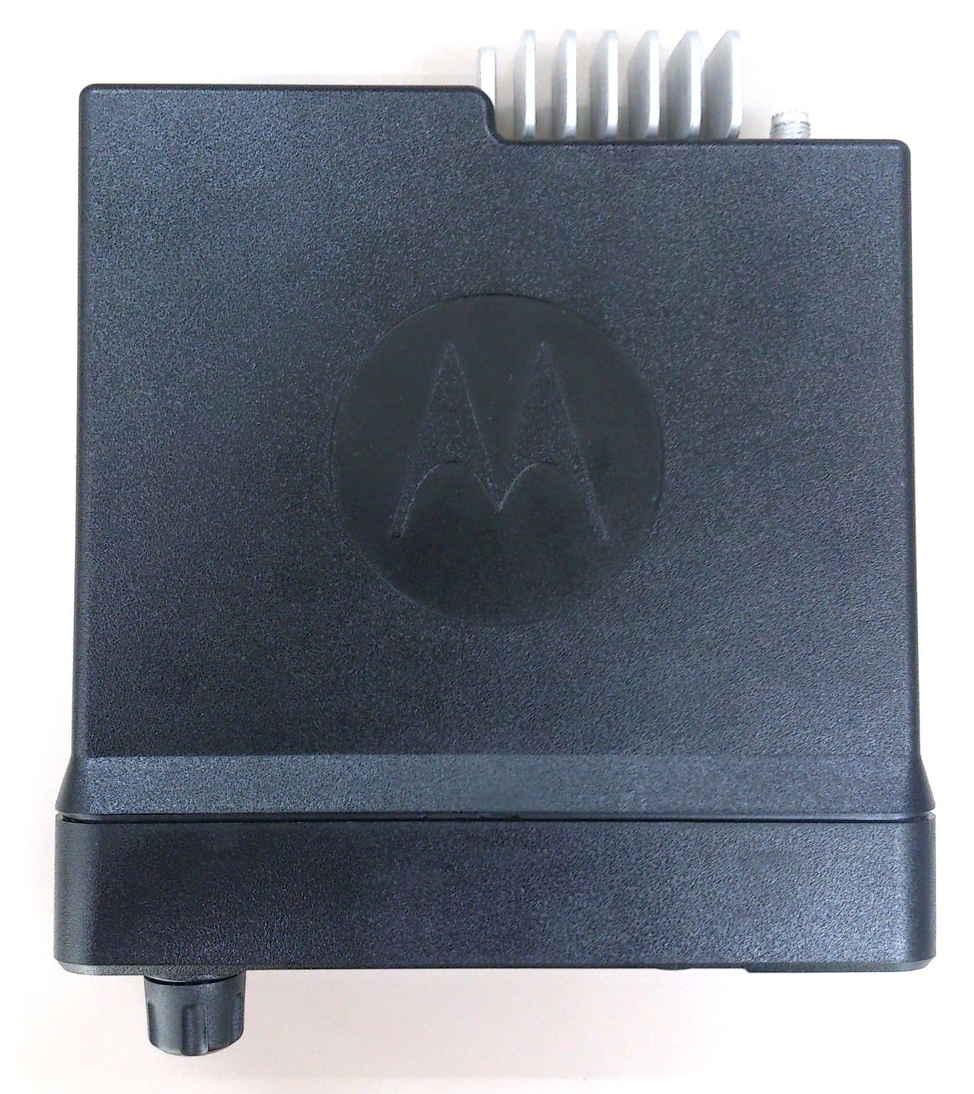
Click to zoom
Application Details
- Equipment Class
- DSS - Part 15 Spread Spectrum Transmitter
- Date of Grant
- May 31, 2021
- Application Purpose
- Original Equipment
- Date of Application
- Apr 26, 2021
- Equipment Note
- Mobile 2 Way Radio
- Frequency Range
- 2402.00000000 - 2480.00000000
- Company
- Motorola Solutions, Inc.
- Country
- United States
Documents & Files
Document Text
Text extracted from the exhibit documents filed with the FCC. Open a document above to read the original.
Users Manual
PROFESSIONAL DIGITAL TWO-WAY RADIO MOTOTRBO™ USER GUIDE FEBRUARY 2021 © 2021 Motorola Solutions, Inc. All rights reserved. MN003677A01-AH @MN003677A01@ en-US XPR 5550/XPR 5550e, XPR 5580/XPR 5580e ALPHANUMERIC DISPLAY MOBILE RADIO fr-CA Contents Supplier's Declaration of Conformity............................ 32 Important Safety Information........................................34 Notice to Users (FCC)..................................................35 Notice to Users (Industry Canada)...............................36 Software Version..........................................................37 Copyrights.................................................................... 38 Computer Software Copyrights.................................... 40 Radio Care................................................................... 41 Chapter 1: Getting Started......................................... 43 1.1 Turning the Radio On.................................. 43 1.2 Turning the Radio Off.................................. 43 1.3 Adjusting the Volume...................................43 Chapter 2: Radio Controls..........................................44 2.1 Volume/Channel Knob.................................44 2.1.1 Setting Dual Knob Operation Preference.............................................. 45 2.2 Keypad Microphone Buttons....................... 46 Chapter 3: WAVE.......................................................48 3.1 WAVE OnCloud/OnPremise........................48 3.1.1 Switching from Radio Mode to WAVE Mode........................................... 48 3.1.2 Making WAVE Group Calls............49 3.1.3 Receiving and Responding to WAVE Group Calls................................. 49 3.1.4 Receiving and Responding to WAVE Private Calls................................50 3.1.5 Switching from WAVE Mode to Radio Mode ........................................... 50 3.2 WAVE Tactical/5000....................................51 3.2.1 Setting Active WAVE Channels ....51 3.2.2 Viewing WAVE Channel Information..............................................51 3.2.3 Viewing WAVE Endpoints Information..............................................52 3.2.4 Changing WAVE Configuration..... 52 3.2.5 Making WAVE Group Calls............53 Part I: Capacity Max...................................................54 4.1 Push-To-Talk (PTT) Button......................... 54 4.2 Programmable Buttons................................54 4.3 Assignable Radio Functions........................55 4.4 Assignable Settings or Utility Functions...... 57 4.5 Accessing Programmed Functions..............57 English 2 4.6 Status Indicators..........................................58 4.6.1 Icons.............................................. 58 4.6.2 LED Indicator.................................64 4.6.3 Tones.............................................65 4.6.3.1 Audio Tones.....................65 4.6.3.2 Indicator Tones................ 66 4.7 Registration................................................. 66 4.8 Zone and Channel Selections..................... 67 4.8.1 Selecting Zones ............................68 4.8.2 Selecting Zones by Using the Alias Search............................................68 4.8.3 Selecting a Call Type.....................69 4.8.4 Selecting a Site..............................69 4.8.5 Roam Request...............................69 4.8.6 Site Lock On/Off............................ 70 4.8.7 Site Restriction...............................70 4.8.8 Site Trunking .................................71 4.9 Calls.............................................................71 4.9.1 Group Calls....................................72 4.9.1.1 Making Group Calls......... 72 4.9.1.2 Making Group Calls by Using the Contacts List................73 4.9.1.3 Making Group Calls by Using the Programmable Number Key ................................74 4.9.1.4 Making Group Calls by Using the Alias Search ................75 4.9.1.5 Responding to Group Calls.............................................77 4.9.2 Broadcast Call .............................. 78 4.9.2.1 Making Broadcast Calls .. 78 4.9.2.2 Making Broadcast Calls Using the Contact List .................79 4.9.2.3 Making Broadcast Calls Using the Programmable Number Key.................................80 4.9.2.4 Receiving Broadcast Calls ............................................80 4.9.3 Private Call.................................... 81 4.9.3.1 Making Private Calls........ 81 4.9.3.2 Making Private Calls by Using the Programmable Number Key ................................82 4.9.3.3 Making Private Calls by Using the Alias Search ................83 English 3 4.9.3.4 Making a Private Call with a One Touch Call Button ..... 85 4.9.3.5 Making Private Calls by Using the Manual Dial..................85 4.9.3.6 Receiving Private Calls....86 4.9.3.7 Accepting Private Calls ...87 4.9.3.8 Declining Private Calls ....87 4.9.4 All Calls .........................................88 4.9.4.1 Making All Calls .............. 88 4.9.4.2 Making All Calls by Using the Programmable Number Key ................................89 4.9.4.3 Making All Calls by Using the Alias Search.................89 4.9.4.4 Receiving All Calls .......... 91 4.9.5 Phone Calls................................... 92 4.9.5.1 Making Phone Calls.........92 4.9.5.2 Making Phone Calls with the Programmable Button .......93 4.9.5.3 Making Phone Calls by Using the Contacts List ...............95 4.9.5.4 Making Phone Calls by Using the Alias Search.................98 4.9.5.5 Making Phone Calls by Using the Manual Dial................100 4.9.5.6 Dual Tone Multi Frequency..................................103 4.9.5.6.1 Initiating DTMF Tone................................103 4.9.5.7 Responding to Phone Calls as All Calls........................ 103 4.9.5.8 Responding to Phone Calls as Group Calls.................. 104 4.9.5.9 Responding to Phone Calls as Private Calls.................104 4.9.6 Initiating Transmit Inter…
Text truncated - open the document above for the full version.
Users Manual
MOTOTRBO ™ Mobile XPR 4000/5000/5000e Series INSTALLATION GUIDE MOTOTRBO ™ MOBILE PROFESSIONAL DIGITAL TWO-WAY RADIO *6880309T23* 6880309T23-FB DECEMBER 2020 © 2020 Motorola Solutions, Inc. All rights reserved Contents List of Figures..............................................................................................................4 List of Tables...............................................................................................................5 Foreword......................................................................................................................6 Product Safety and RF Exposure Compliance.............................................................................. 6 Computer Software Copyrights......................................................................................................6 Document Copyrights.................................................................................................................... 6 Disclaimer......................................................................................................................................6 Trademarks....................................................................................................................................6 Document History.......................................................................................................8 Related Publications...................................................................................................9 Notations Used in This Manual................................................................................10 Mobile Radio Model Numbering Scheme................................................................11 Commercial Warranty...............................................................................................13 I. What This Warranty Covers And For How Long.......................................................................13 II. General Provisions.................................................................................................................. 13 III. State Law Rights (Applicable Only in U.S.A.).........................................................................14 IV. How To Get Warranty Service................................................................................................14 V. What This Warranty Does Not Cover......................................................................................14 VI. Patent And Software Provisions.............................................................................................14 VII. Governing Law...................................................................................................................... 15 Chapter 1: Introduction...........................................................................................16 1.1 Mobile Radio Description.......................................................................................................16 1.1.1 Dimensions.............................................................................................................. 16 1.1.2 Connections on the Back of the Radio.....................................................................17 1.2 Standard Configurations........................................................................................................18 1.2.1 Dash Mount Configuration....................................................................................... 18 1.2.2 Remote Mount Configuration...................................................................................19 1.3 Base/Control Stations ...........................................................................................................19 Chapter 2: Installation Details for Standard Configurations...............................21 2.1 Planning the Installation.........................................................................................................21 2.1.1 Tools Required for Installation................................................................................. 21 2.1.2 Installation Example.................................................................................................21 2.1.3 Wiring Diagrams...................................................................................................... 22 2.2 Radio Mounting......................................................................................................................24 2.2.1 Dash Mount with Trunnion.......................................................................................25 6880309T23-FB Contents 2 2.2.2 Locking Kit (Optional)...............................................................................................27 2.2.2.1 Installing Locking Kit for All Radios............................................................27 2.3 DIN Mount..............................................................................................................................28 2.3.1 Installing the Frame into the Dashboard..................................................................28 2.3.2 Mounting the Radio in the Frame.............................................................................29 2.3.3 Removing the Radio from the Frame.......................................................................30 2.4 Remote Mount with Trunnion.................................................................................................30 2.5 Power Cables........................................................................................................................ 31 2.6 Ignition Sense Cable..............................................................................................................32 2.7 Antenna Installation............................................................................................................... 33 2.7.1 Selecting an Antenna Site/Location on a Metal Body Vehicle............…
Text truncated - open the document above for the full version.
Users Manual
en-US es-LA fr-CA pt-BR RF Energy Exposure Training and Product Safety Information for Mobile Two-Way Radios installed in Vehicles or as Fixed Site Control Stations Formation sur l’exposition aux RF et information sur la sécurité du produit pour radios bidirectionnelles mobiles installées dans des v éhicules ou comme stations de contrôle à emplacements fixes Capacitación sobre la exposición a energía de radiofrecuencia e información de protección del producto para radios de dos vías móviles instalados en vehículos o como estaciones de control fijas Treinamento sobre a Exposição à Energia de RF e Informações de Segurança do Produto para Rádios Portáteis Bidirecionais Instalados em Veículos ou como Estações de Controle de Site Fixo https://learning.motorolasolutions.com/User_Documentation Caution Before using this radio, read this booklet which contains important operating instructions. For information on product details, brochures, user manuals and approved accessories. Please refer to www.motorolasolutions.com. Compliance with RF Exposure Standards National and international regulations require manufacturers to comply with the RF energy exposure limits for mobile two-way radios before they can be marketed. Your Motorola Solutions two-way radio is designed, manufactured, and tested to comply with all applicable national and international regulations for human exposure to radio frequency electromagnetic energy. When two-way radios are used as a consequence of employment, applicable regulations may require users to be fully aware of and able to control their exposure to meet occupational requirements. RF Energy Exposure Awareness and Control Information and Operational Instructions for Occupational Use Notice: This radio is intended for use in occupational/controlled conditions where users are aware of their exposure and can exercise control over their exposure to meet the requirements in national and international regulations. This radio device is not authorized for general population, consumer use. For more information on what RF energy exposure is, and how to control your exposure to ensure compliance with established RF exposure limits, consult the following websites: •https://www.fcc.gov/ •https://www.osha.gov/ •https://osha.europa.eu/en •http://www.who.int/peh-emf/project/en/ •http://www.ic.gc.ca/eic/site/smt-gst.nsf/eng/sf11467.html •http://www.ic.gc.ca/eic/site/smt-gst.nsf/eng/sf01904.html For additional user training information on exposure requirements, consult the following websites: •https://www.motorolasolutions.com/en_us/about/company-overview/corporate- responsibility/governance-and-policies/wireless-communication-and-health- faqs.html •http://learning.motorolasolutions.com/ English 1 RF Exposure Compliance and Control Guidelines To control exposure to yourself and others, and to ensure compliance with the relevant RF exposure limits, always adhere to the following guidelines: • Do not remove any of the RF Exposure Labels if present from this device or its related accessories. • Attach these instructions to the device when you transfer it to other users. •Do not use this device if the operational requirements described herein are not met. Operating Instructions • Transmit no more than 50% of the time. To transmit (talk), press the Push-To- Talk (PTT) button. To receive calls, release the PTT button. Transmitting more than 50% of the time may cause RF exposure compliance requirements to be exceeded. • Transmit only when people (bystanders) outside the vehicle are at least at the recommended minimum lateral distance (as shown in Tables 1 and 2) away from the vehicle body. This separation will ensure that there is sufficient distance from a properly installed (according to the installation instructions) externally-mounted antenna to satisfy the relevant RF exposure limits. • To ensure continued compliance with applicable RF exposure limits, use only Motorola Solutions approved, supplied or replacement antennas, batteries, and accessories. • For a list of Motorola Solutions approved accessories please refer to your user manual or visit www.motorolasolutions.com Table 1 lists the recommended lateral distance for bystanders from the body of a vehicle (For example, truck, van, car, motorcycle) equipped with an approved, properly installed single-band mobile radio and associated antenna(s). These lateral distances, for single-band radios, depend on the radio rated power. Table 1: Rated Power of Vehicle-Installed Single-Band Mobile Radio and Recommended Minimum Lateral Distance from Vehicle Body Single-Band Mobile Radio Rated Power (see Notice) Minimum Lateral Distance of By- standers from Vehicle Body Less than 7 W8 in. (20 cm) 7 to 14 W1 ft (30 cm) 15 to 39 W2 ft (60 cm) 40 to 110 W3 ft (90 cm) English 2 Notice: If you are not sure of the rated power of your single-band radio, contact your Motorola Solutions representative or dealer and supply the radio model number found on the radio model label. If you cannot determine the rated power, then assure 3 ft (90 cm) separation for bystanders from the body of the vehicle. Table 2 lists the recommended lateral distance for bystanders from the body of a vehicle (For example, truck, van, car, motorcycle) equipped with an approved, properly installed multi-band mobile radio and associated antenna(s). These lateral distances, for multi-band radios, depend on whether the radio is installed on a motorcycle, or on other kinds of vehicles. Table 2: Rated Power of Vehicle-Installed Multi-Band Mobile Radio and Recommended Minimum Lateral Distance from Vehicle Body Type of Vehicle Minimum Lateral Distance of By- standers from Vehicle Body Motorcycle2 ft (60 cm) Other vehicles3 ft (90 cm) Mobile Antenna Installation Guidelines • Make sure to follow the antenna installation guidelines that are provided in this mobile radio installation manual. • Use only Motorola Solutions approved supplied antenna, or a Motorola Solutions approved replacement antenna…
Text truncated - open the document above for the full version.
Cover Letter(s)
Applicant: Motorola Solutions Inc FCC ID: AZ492FT7140/ IC: 109U-92FT7140 EXHIBIT 2 SHEET 1 OF 2 EXHIBIT 2 Statement of Certification (Pursuant to FCC Part 2.907, 2.908 and RSP 100 Sec 4) 2.1 Statement of Certification Transceiver type described herein (AZ492FT7140/109U-92FT7140) is in compliance with all applicable parts of the FCC rules and ISED RSS standards. Each unit manufactured, imported, or marketed will conform to the samples tested herein, within the statistical variations that can be expected due to high volume production and test measurement error. NAME: Jeff Linn SIGNATURE: DATE: 20 th Jan 2021 TITLE: Engineering Manager Applicant: Motorola Solutions Inc FCC ID: AZ492FT7140/ IC: 109U-92FT7140 EXHIBIT 2 SHEET 2 OF 2 2.2 Attestation Statement (Equipment Class DTS and DSS – Bluetooth/WiFi) This device contains an embedded Bluetooth device and WiFi device that are compliant with the applicable FCC Part 15C and ISED RSS 247 regulations. Part 15.247 (a)(1) / RSS 247 Section 5.1 • The hopping sequence must be pseudo random. • Each frequency must be used equally on the average by each transmitter • The receivers input bandwidth is approximately equal to the transmit bandwidth • The receiver hops in sequence with the transmitted signal Part 15.247 (g) / RSS 247 Section 5.1 • The system is designed to comply with all of the regulations in this section when the transmitter is presented with a continuous data (or information) Part 15.247(h) / RSS 247 Section 5.1 • The system does not coordinate its channel selection/hopping sequence with other frequency hopping systems for the express purpose of avoiding the simultaneous occupancy of individual hopping frequencies by multiple transmitters. NAME: Jeff Linn SIGNATURE: DATE: 20 th Jan 2021 TITLE: Engineering Manager
Cover Letter(s)
FCC ID: AZ492FT7140 _______________________________________________________________________________________________________________________ Motorola Solutions Malaysia Sdn Bhd, Plot 2A, Medan Bayan Lepas, Mukim 12 SWD, 11900 Bayan Lepas, Penang, Malaysia EXHIBIT 13A Date: April 23, 2021 Office of Engineering and Technology Laboratory Division Equipment Authorization Branch Federal Communications Commission Laboratory 7435 Oakland Mills Road Columbia, MD 21046 Subject: Application for Certification of Transmitter with FCC ID: AZ492FT7140 Dear Sir/Madam, Motorola Solutions Malaysia Sdn. Bhd. herein submits application for Certification of the subject transmitter. This transmitter is intended for use in a Mobile and Fixed use radio application with capabilities for clear and coded communications with a variable transmit power operating within the following frequency ranges: We are requesting certification under Part(s) of the Commission’s Rules listed above to allow operation of this equipment. The subject transmitter complies with Section 90.203 of the Rules in that the operator cannot directly program transmit frequencies using the unit's normally accessible external controls. A complete Certification application is enclosed. If you require any additional information, please contact me at +604–2240258. Sincerely, Arine Lee FCC/IC Certification Manager E-mail : [email protected] Product Name Model Numbers Frequency Range RF Power FCC Rules Part XPR 5350e XPR 5550e XPR 5550e AAM28QPC9RA1AN AAM28QPN9RA1AN AAM28QPN9WA1AN LMR: 403 - 470 MHz 1-40W; Max = 48 W 22, 74, 90 BT: 2402-2480 MHz 2.93 mW (max measured conducted peak) 15C BTLE 4.0: 2402-2480 MHz 3.74 mW (max measured conducted average) 15C WLAN 802.11 b/g/n: 2412-2462 MHz 802.11b: 17.64 mW (max measured conducted average) 802.11g: 12.10 mW (max measured conducted average) 802.11n: 8.29 mW (max measured conducted average) 15C
Cover Letter(s)
FCC ID: AZ492FT7140 _______________________________________________________________________________________________________________________ Motorola Solutions Malaysia Sdn Bhd, Plot 2A, Medan Bayan Lepas, Mukim 12 SWD, 11900 Bayan Lepas, Penang, Malaysia EXHIBIT 13B CONFIDENTIALITY REQUEST Date: April 23, 2021 Office of Engineering and Technology Laboratory Division Equipment Authorization Branch FCC Laboratory 7435 Oakland Mills Road Columbia, MD 21046 Subject: Confidentiality Request for Transmitter with FCC ID: AZ492FT7140 Dear Sir / Madam, Motorola Solutions Malaysia Sdn Bhd is requesting that Exhibit 4 (Circuit Descriptions), Exhibit 5 (Schematic Diagrams), Exhibit 10 (Parts List and Tune Up Procedures), and Exhibit 12 (Operational Description) not be made routinely available for public inspection. Motorola Solutions considers the information in these exhibits to be classified as trade secrets, pursuant to 47 CFR Section 0.457(d), 0.459 and Section 552(b)(4) of the Freedom of Information Act. Please mark Exhibits 4, 5, 10, and 12 as “Confidential.” Please contact me if you require any additional information. Sincerely, Arine Lee FCC/IC Certification Manager E-mail : [email protected]
Cover Letter(s)
____________________________________________________________________________ Motorola Solutions Inc, 8000 West Sunrise Boulevard, Fort Lauderdale, Florida 33322 Certification Department Date: 22 February 2021 Subject: Application Authorization for FCC/IC filing To Whom It May Concern: I hereby authorize Arine Lee to apply, on my behalf, the application for the following FCC/IC ID: FCC/IC ID: AZ492FT7140 / 109U-92FT7140 Please contact me if there are any questions or issues. Regards, Deanna Zakharia Regulatory Compliance Manager Tel: (954) 723 4707 Email: [email protected]
Cover Letter(s)
FCC ID: AZ492FT7140 _______________________________________________________________________________ Motorola Solutions Malaysia Sdn Bhd, Plot 2A, Medan Bayan Lepas, Mukim 12 SWD, 11900 Bayan Lepas, Penang, Malaysia EXHIBIT 13C April 23, 2021 Authorization & Evaluation Division Federal Communications Commission Laboratory 7435 Oakland Mills Road Columbia, MD 21046 Subject: Extended Frequencies Justification for Certification of Transmitter with FCC ID: AZ492FT7140. Dear Sir/Madam: This transmitter is designed to operate in the following frequency ranges: Band/Mode Frequency ranges FCC Rule Parts UHF 403-470 MHz 22, 74, 90 Bluetooth 2402 – 2480 MHz 15C Bluetooth LE 2402 – 2480 MHz 15C Wi-Fi/ WLAN 2412 – 2462 MHz 15C To aid equipment authorization in other countries which accept the United States FCC Grant for Certification, Motorola Solutions is requesting that the FCC lists the above applicable frequencies range under FCC Rule Parts 22, 74 and 90 on the FCC Grant. For the FCC’s Rule Parts 22, 74 and 90 applications, this radio is used in systems by Federal and Public Safety agencies including Police, Fire, and Emergency Medical Services, etc. as indicated in the table below. Equipment programming is the responsibility of Authorized Service Personnel. Also, the radio complies with 47 CFR Part 90.203(e), in that the operator cannot directly program the transmit frequencies using the normally accessible external controls. Per the FCC’s KDB634817 guidance, “as an alternative to listing the exact frequencies, we acknowledge that it’s a violation of the FCC Rules if this device operates on unauthorized frequencies. Frequency Range (MHz) Part 22 Part 74 Part 90 Federal Other Regions 403-406 x 406.1-450 x 450-454 x x 454-456 x 456-460 x x 460-462.5375 x 462.5375-462.7375* x x 462.7375-467.5375 x 467.5375-467.7375 467.7375-470 x *Canada Please contact me if you required any additional information. Sincerely, _____ Arine Lee FCC/IC Certification Manager E-mail : [email protected]
External Photos
Applicant: Motorola Solutions Inc FCC ID: AZ492FT7140/ IC: 109U-92FT7140 EXHIBIT 3 SHEET 1 OF 6 EXHIBIT 3 EXTERNAL PHOTOGRAPHS (Pursuant to FCC Part 2.1033(b)(7) and 2.1033(c)(12) and RSP 100 Annex C) The following photographs are attached. Exhibit 1. Front View 3A 2. Back View . 3B 3. Top View 3C 4. Bottom View (FCC/IC Label Location) 3D 5. Side View (Left) 3E 6. Side View (Right) 3F Applicant: Motorola Solutions Inc FCC ID: AZ492FT7140/ IC: 109U-92FT7140 EXHIBIT 3 SHEET 2 OF 6 EXHIBIT 3A - Front View Front View (XPR 5550e - Color Display) Front View (XPR 5350e - Numeric Display) Applicant: Motorola Solutions Inc FCC ID: AZ492FT7140/ IC: 109U-92FT7140 EXHIBIT 3 SHEET 3 OF 6 EXHIBIT 3B – Back View Back View (same for XPR 5550e Color Display and XPR 5350e Numeric Display) Applicant: Motorola Solutions Inc FCC ID: AZ492FT7140/ IC: 109U-92FT7140 EXHIBIT 3 SHEET 4 OF 6 EXHIBIT 3C – Top View Top View (Same for XPR 5550e Color Display and XPR 5350e Numeric Display) Applicant: Motorola Solutions Inc FCC ID: AZ492FT7140/ IC: 109U-92FT7140 EXHIBIT 3 SHEET 5 OF 6 EXHIBIT 3D –Bottom View (FCC/IC Label Location) Bottom View (FCC/IC Label Location) Same for XPR 5550e Color Display and XPR 5350e Numeric Display Applicant: Motorola Solutions Inc FCC ID: AZ492FT7140/ IC: 109U-92FT7140 EXHIBIT 3 SHEET 6 OF 6 EXHIBIT 3E - Side View (Left) Side View (Left) – Same for XPR 5550e Color Display and XPR 5350e Numeric Display EXHIBIT 3F - Side View (Right) Side View (Right) – Same for XPR 5550e Color Display and XPR 5350e Numeric Display *** END ***
ID Label/Location Info
Applicant: Motorola Solutions Inc. FCC ID: AZ492FT7140 / IC: 109U-92FT7140 EXHIBIT 2 SHEET 1 OF 2 EXHIBIT 1 IDENTIFICATION LABEL (Pursuant to FCC Part 2.1033(c)(11), 2.1033(b)(7) and RSP 100 Annex C and Sec 3) LOCATION See the Attached Photograph or Sketch Bottom of Radio Top of Radio X Back of Radio Back of Radio under Belt Clip In the Battery Compartment Electronic labeling: In the user manual (Section: XX) TYPE X The label is a polyester film laminate with a pressure sensitive adhesive backing. The adhesive is a permanent type acrylic with the minimum peel strength of 32 oz/inch. MARKINGS (TEXT) X See the Attached Photograph and Exhibit 3D for the actual location of the FCC label on the device. X Label Attached Below. See Attached Drawing. Applicant: Motorola Solutions Inc. FCC ID: AZ492FT7140 / IC: 109U-92FT7140 EXHIBIT 2 SHEET 2 OF 2 Figure 1: FCC/IC Label for XPR 5550e 403-470MHz 40W GOB BT/GNSS/WiFi Color Display Figure 2: FCC/IC Label for XPR 5550e 403-470MHz 40W GOB GNSS CFS BT/WiFi Color Display Applicant: Motorola Solutions Inc. FCC ID: AZ492FT7140 / IC: 109U-92FT7140 EXHIBIT 2 SHEET 3 OF 2 Figure 3: FCC/IC Label for XPR 5350e 403-470MHz 40W GOB BT/GNSS/WiFi Numeric Display Figure 4: RF Exposure Warning Label
Internal Photos
Applicant: Motorola Solutions Inc. FCC ID: AZ492FT7140/ IC: 109U-92FT7140 Exhibit 9 Page | 1 EXHIBIT 9 Internal Photographs (Pursuant to FCC Part 2.1033(b)(7), 2.1033(c)(12) and RSP 100 Annex C) The following photographs are attached. Exhibit 1. RF board with Shields (Top) 9A 2. RF board without Shields (Top) 9B 3. RF board with Shields (Bottom) 9C 4. RF board without Shields (Bottom) 9D 5. Chassis and control heads (Top) 9E 6. Chassis and control heads (Bottom) 9F 7. GOB board (Top) 9G 8. GOB board with Shields (Bottom) 9H 9. GOB board without Shields (Bottom) 9I 10. Expansion Board (Top) 9J 11. Expansion board with Shields (Bottom) 9K 12. Expansion board without Shields (Bottom) 9L Applicant: Motorola Solutions Inc. FCC ID: AZ492FT7140/ IC: 109U-92FT7140 Exhibit 9 Page | 2 Exhibits 9A RF board with Shields (Top) Exhibits 9B RF board without Shields (Top) Applicant: Motorola Solutions Inc. FCC ID: AZ492FT7140/ IC: 109U-92FT7140 Exhibit 9 Page | 3 Exhibits 9C RF board with Shields (Bottom) Exhibits 9D RF board without Shields (Bottom) TCXO Applicant: Motorola Solutions Inc. FCC ID: AZ492FT7140/ IC: 109U-92FT7140 Exhibit 9 Page | 4 Exhibits 9E Chassis and control heads (Top) Exhibits 9F Chassis and control heads (Bottom) Applicant: Motorola Solutions Inc. FCC ID: AZ492FT7140/ IC: 109U-92FT7140 Exhibit 9 Page | 5 Exhibits 9G GOB board (Top) Exhibits 9H GOB board with shield (Bottom) Applicant: Motorola Solutions Inc. FCC ID: AZ492FT7140/ IC: 109U-92FT7140 Exhibit 9 Page | 6 Exhibits 9I GOB board without shield (Bottom) Exhibits 9J Expansion board (Top) BT/WiFi test port GPS port Applicant: Motorola Solutions Inc. FCC ID: AZ492FT7140/ IC: …
Text truncated - open the document above for the full version.
Contact Information
Applicant
Arine Lee(Certification Manager)
Test Firm
Motorola Penang Advanced Communication LaboratoryMohd Azuan Shah Yaakap
Technical Specifications
| # | Rule Parts | Frequency Range | Power Output |
|---|---|---|---|
| 1 | 15C | 2.40 GHz - 2.48 GHz | 2.93 mW |
Other Applications from Motorola Solutions, Inc.

AZ489FT4980
Sep 08, 2026Portable two way radio
Equipment Class
TNF - Licensed Non-Broadcast Transmitter Held to FaceAZ489FT4981
Aug 14, 2026Handheld Portable - TANAPA BPR 45 400-470 MHZ 4W NKP
Equipment Class
TNF - Licensed Non-Broadcast Transmitter Held to Face
AZ489FT7187
Jul 13, 2026Portable 2-Way Radio with Bluetooth, Bluetooth LE, WIFI 2.4GHz, WIFI 5GHz, LTE
Equipment Class
DSS - Part 15 Spread Spectrum TransmitterAZ499FT6031
May 11, 2026Operation Critical Wireless Earpiece PTT
Equipment Class
DSS - Part 15 Spread Spectrum Transmitter
AZ499FT5879
Dec 19, 20252-way Portable Radio with BT, BTLE, WIFI, NFC and LTE
Equipment Class
DSS - Part 15 Spread Spectrum Transmitter