AZD233Wireless Module
Canon Inc.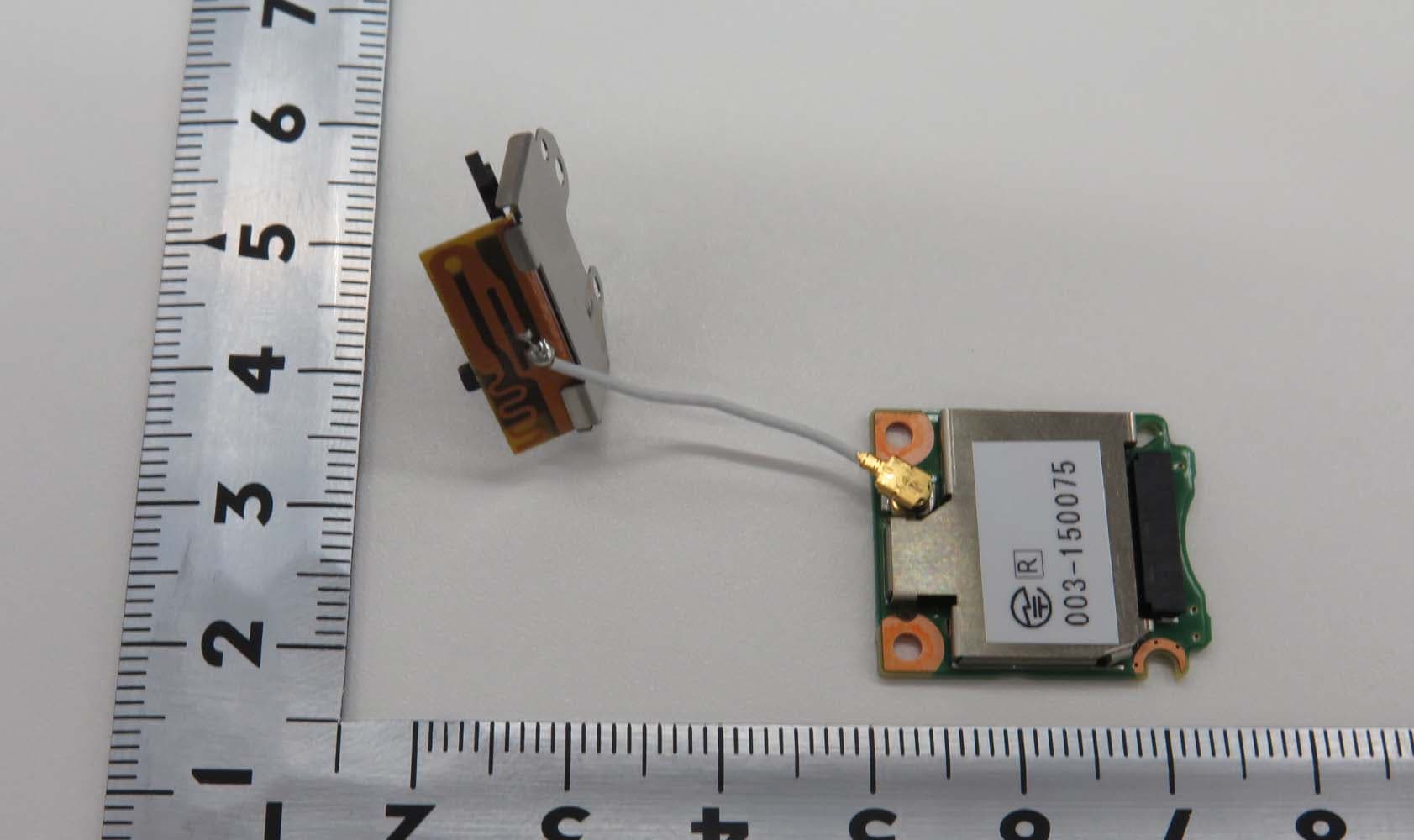
Click to zoom
Application Details
- Equipment Class
- NII - Unlicensed National Information Infrastructure TX
- Date of Grant
- Dec 23, 2015
- Application Purpose
- Original Equipment
- Date of Application
- Dec 23, 2015
- Equipment Note
- Wireless Module
- Frequency Range
- 5745.00000000 - 5825.00000000
- Company
- Canon Inc.
- Country
- Japan
Documents & Files
Document Text
Text extracted from the exhibit documents filed with the FCC. Open a document above to read the original.
Users Manual
We don't prepare the User Manual for the module because it is not sold to the end user directly. Please refer to the Specification Sheet for more details about the module. For the module installation to the host equipment please follow the interface specification (installation procedure) FCC/IC Notice for model: ES201 Following statement must be included in the user manual of host device. The end p roduct must be labeled For the module installation to the host equipment , please follow the interface specification (installation procedure) . FCC/IC NOTICE Mdl DS586091 (i l di WLAN Mdl Mdl ES201 FCC ID AZD233/IC 498J 233) p “Contains FCC ID: AZD233” and “Contains IC: 498J ‐ 233” Model: DS586091 is the host device of ES201. M o d e l : DS586091 (i nc l u di ng WLAN M o d u l e M o d e l ES201 , FCC ID : AZD233/IC : 498J ‐ 233) This device complies with part 15 of FCC Rules and Industry Canada’s licence ‐ exempt RSSs. Operation is subject to the following two conditions: (1) this device may not cause harmful interference, and (2) thi di t t it f id ildi it f th t did ti (2) thi s d ev i ce mus t accep t any i n t er f erence rece i ve d , i nc l u di ng i n t er f erence th a t may cause un d es i re d opera ti on. Do not make any changes or modifications to the equipment unless otherwise specified in the manual. If such changes or modifications should be made, you could be required to stop operation of the equipment. This transmitter must not be co ‐ located or operated in conjunction with any other antenna or transmitter except Canon accessories supplied or designated for this product. The available scientific evidence does not show that any health problems are associated with using low power wireless devices T here is no proof The available scientific evidence does not show that any health problems are associated with using low power wireless devices . T here is no proof , however, that these low power wireless devices are absolutely safe. Low power Wireless devices emit low levels of radio frequency energy (RF) in the microwave range while being used. Whereas high levels of RF can produce health effects (by heating tissue), exposure of low ‐ level RF that does not produce heating effects causes no known adverse health effects. Many studies of low ‐ level RF exposures have not found any biological effects. Some studies have suggested that some biological effects might occur, but such findings have not been confirmed by additional research. This model has been tested and found to comply with FCC/IC radiation exposure limits set forth for an uncontrolled environment and meets the FC C radio frequency been tested and found to comply with FCC/IC radiation exposure limits set forth for an uncontrolled environment and meets the FC C radio frequency (RF) Exposure Guidelines and RSS ‐ 102 of the IC radio frequency (RF) Exposure rules.
ID Label/Location Info
Label of ES201 Label location of ES201
RF Exposure Info
Test report No. : 10882639S-A Page : 19 of 78 Issued date : December 1, 2015 FCC ID : AZD233 UL Japan, Inc. Shonan EMC Lab. 1-22-3 Megumigaoka, Hiratsuka-shi, Kanagawa-ken, 259-1220 JAPAN Telephone: +81 463 50 6400 / Facsimile: +81 463 50 6401 APPENDIX 2: SAR Measurement data Appendix 2-1: Evaluation procedure The SAR evaluation was performed with the following procedure: Step 1: Measurement of the E-field at a fixed location above the central position of flat phantom was used as a reference value for assessing the power drop. Step 2: The SAR distribution at the exposed side of head or body position was measured at a distance of each device from the inner surface of the shell. The area covered the entire dimension of the antenna of EUT and suitable horizontal grid spacing of EUT. Based on these data, the area of the maximum absorption was determined by splines interpolation. Step 3: Around this point found in the Step 2 (area scan), a volume of more than or equal to 30mm(X axis)30mm(Y axis)30mm(Z axis) was assessed by measuring 777 points (or more) under 3GHz and a volume of more than or equal to 28mm(X axis)28mm(Y axis)24mm (Z axis) was assessed by measuring 887 (ratio step method (*1)) points (or more) for 3-6GHz frequency band. Any additional peaks found in the Step2 which are within 2dB of limit are repeated with this Step3 (Zoom scan). On the basis of this data set, the spatial peak SAR value was evaluated under the following procedure: (1) The data at the surface were extrapolated, since the center of the dipoles is 1mm away from the tip of the probe and the distance between the surface and the lowest measuring point is 2mm. The extrapolation was based on a least square algorithm. A polynomial of the fourth order was calculated through the points in z-axes. This polynomial was then used to evaluate the points between the surface and the probe tip. (2) The maximum interpolated value was searched with a straightforward algorithm. Around this maximum the SAR values averaged over the spatial volumes (1g or 10g) were computed by the 3D-Spline interpolation algorithm. The 3D-Spline is composed of three one-dimensional splines with the “Not a knot"-condition (in x, y and z-directions). The volume was integrated with the trapezoidal-algorithm. One thousand points (101010) were interpolated to calculate the average. (3) All neighboring volumes were evaluated until no neighboring volume with a higher average value was found. Step 4: Re-measurement of the E-field at the same location as in Step 1 for the assessment of the power drift. Step 5: Repeat Step 1-Step 4 with other condition or/and setup of EUT. *1. Ratio step method parameters used; the first measurement point: “1.4mm” from the phantom surface, the initial grid separation: “1.4mm”, subsequent graded grid ratio: “1.4”. These parameters comply with the requirement of the KDB 865664 D01 (v01r03) and recommended by Schmid & Partner Engineering AG (DASY5 manual). Test report No. : 10882639S-A Page : 20 of 78 Issued date : December 1, 2015 FCC ID : AZD233 UL Japan, Inc. Shonan EMC Lab. 1-22-3 Megumigaoka, Hiratsuka-shi, Kanagawa-ken, 259-1220 JAPAN Telephone: +81 463 50 6400 / Facsimile: +81 463 50 6401 Appendix 2-2: SAR measurement data Step 1 (2.4GHz): Worst SAR search of DSSS mode Plot 1-1: Setup (DSSS): Left & touch, 11b(1Mbps), 2437 MHz ->Highest reported SAR(1g) / DTS, 2.4GHz band EUT: Wireless Module (in Wireless File Transmitter); Type: ES201 (DS586091); Serial: 5I52 (36) Mode: 11b(1Mbps)(DBPSK/DSSS)(UID 0, Frame Length in ms: 0; PAR: 0; PMF: 1); Frequency: 2437 MHz; Crest Factor: 1.0 Medium: M2450(150928); Medium parameters used: f = 2437 MHz; σ = 1.998 S/m; ε r = 50.43; ρ = 1000 kg/m 3 Measurement Standard: DASY5 (IEEE/IEC/ANSI C63.19-2007) DASY Configuration: -Probe: EX3DV4 - SN3907; ConvF(7.17, 7.17, 7.17); Calibrated: 2015/04/23; -DASY52 52.8.8(1222); SEMCAD X 14.6.10(7331) -Sensor-Surface: 2mm (Mechanical Surface Detection), z = 1.0, 31.0 -Electronics: DAE4 Sn554; Calibrated: 2015/04/24 -Phantom: ELI v4.0; Type: QDOVA001BA; Serial: 1059; Phantom section: Flat Section portable(body-touch)(kdb248227v02)/b8,left&touch(d0mm),11b(1m,set:15),m2437/ Area Scan:84x72,stp12 (8x7x1): Measurement grid: dx=12mm, dy=12mm; Maximum value of SAR (measured) = 0.584 W/kg Area Scan:84x72,stp12 (71x61x1): Interpolated grid: dx=1.200 mm, dy=1.200 mm; Maximum value of SAR (interpolated) = 1.02 W/kg Z Scan:160,5 (1x1x33): Measurement grid: dx=20mm, dy=20mm, dz=5mm; Maximum value of SAR (measured) = 0.923 W/kg Zoom Scan:30x30x30,stp5 (7x7x7)/Cube 0: Measurement grid: dx=5mm, dy=5mm, dz=5mm; Reference Value = 21.35 V/m; Power Drift = 0.07 dB; Maximum value of SAR (measured) = 0.926 W/kg; Peak SAR (extrapolated) = 1.29 W/kg SAR(1 g) = 0.589 W/kg; SAR(10 g) = 0.257 W/kg Remarks: *. Date tested: 2015/09/28; Tested by: Hiroshi Naka; Tested place:No.7 shielded room, *. liquid depth: 152 mm; Position: distance of EUT to phantom: 0 mm (2 mm to liquid); ambient: 23.5 1 deg.C. / 50 10 %RH, *. liquid temperature: 22.7(start)/22.7(end)/22.3(in check) deg.C.; *. White cubic: zoom scan area, Red cubic: big=SAR(10g )/small=SAR(1g) Test report No. : 10882639S-A Page : 21 of 78 Issued date : December 1, 2015 FCC ID : AZD233 UL Japan, Inc. Shonan EMC Lab. 1-22-3 Megumigaoka, Hiratsuka-shi, Kanagawa-ken, 259-1220 JAPAN Telephone: +81 463 50 6400 / Facsimile: +81 463 50 6401 Appendix 2-2: SAR measurement data / Step 1 (2.4GHz): Worst SAR search of DSSS mode (cont'd) Plot 1-2: Setup (DSSS): Front & touch, 11b(1Mbps), 2437 MHz EUT: Wireless Module (in Wireless File Transmitter); Type: ES201 (DS586091); Serial: 5I52 (36) Mode: 11b(1Mbps)(DBPSK/DSSS)(UID 0, Frame Length in ms: 0; PAR: 0; PMF: 1); Frequency: 2437 MHz; Crest Factor: 1.0 Medium: M2450(150928); Medium parameters used: f = 2437 MHz; σ = 1.998 S/m; ε r = 50.43; ρ = 1000 kg/m 3 Measurement Standard: DASY5 (IEEE/IEC/ANSI C63.19-2007) DASY Configuration: -Probe: EX3DV4 - SN3907; ConvF(7.17, 7.17, 7.17…
Text truncated - open the document above for the full version.
RF Exposure Info
Test report No. : 10882639S-A Page : 1 of 78 Issued date : December 1, 2015 FCC ID : AZD233 UL Japan, Inc. Shonan EMC Lab. 1-22-3 Megumigaoka, Hiratsuka-shi, Kanagawa-ken, 259-1220 JAPAN Telephone: +81 463 50 6400 / Facsimile: +81 463 50 6401 SAR TEST REPORT Test Report No.: 10882639S-A Applicant : Canon Inc. Type of Equipment : Wireless Module Model No. : ES201 (*. Installed into the limited platform: Wireless transmitter) FCC ID : AZD233 Test Standard : FCC 47CFR §2.1093 Test Result : Complied Highest Reported SAR(1g) Value PlatformHost device Remarks Type Mode l Type Model 0.70 W/kg (measured: 0.589W/kg) Wireless File Transmitter DS586091 Digital Camera DS126561 (DTS) 2437 MHz, 802.11b (1Mbps, DSSS) (output power: 14.78 dBm). 1.18 W/kg (measured: 0.842W/kg) (UNII) 5500 MHz, 802.11a (6Mbps, OFDM) (output power: 12.06 dBm) *. Highest reported SAR (1g) across this platform and exposure conditions (body-touch) = "1.18 W/kg” = grant listing. *. Since highest reported SAR (1g) on a platform with a specified host device for DS586091 (EUT) which obtained in accordance with KDB447498 D01 (v05r02) was > 0.8 W/kg and 1.2 W/kg, this EUT is approved to operate a single platform 1. This test report shall not be reproduced in full or partial, without the written approval of UL Japan, Inc. 2. The results in this report apply only to the sample tested. 3. This sample tested is in compliance with the limits of the above regulation. 4. The test results in this test report are traceable to the national or international standards. 5. This test report must not be used by the customer to claim product certification, approval, or endorsement by any agency of the Federal Government. 6. The opinions and the interpretations to the result of the description in this report are outside scopes where UL Japan has been accredited. 7. This test report covers Radio technical requirements. It does not cover administrative issues such as Manual or non-Radio test related Requirements. (if applicable) Date of test: September 28, 29 and 30, 2015 Test engineer: Hiroshi Naka Engineer, Consumer Technology Division Approved by: Toyokazu Imamura Leader, Consumer Technology Division The testing in which "Non-accreditation" is displayed is outside the accreditation scopes in UL Japan. There is no testing item of "Non-accreditation". RTL02610 13-EM-F0429 Revised date : December 21, 2015(-r01) Test report No. : 10882639S-A Page : 2 of 78 Issued date : December 1, 2015 FCC ID : AZD233 UL Japan, Inc. Shonan EMC Lab. 1-22-3 Megumigaoka, Hiratsuka-shi, Kanagawa-ken, 259-1220 JAPAN Telephone: +81 463 50 6400 / Facsimile: +81 463 50 6401 REVISION HISTORY Revision Test report No. Date Page revisedContents Original 10882639S-A December 1, 2015 - - -r01 10882639S-A December 21, 2015 p1,2,12,28,31 (p12,28,31) Error correction. *. By issue of new revision report, the report of an old revision becomes invalid. CONTENTS PAGE REVISION HISTORY ................................................................................................................................................... 2 CONTENTS .................................................................................................................................................... 2 SECTION 1: Customer information ................................................................................... 3 SECTION 2: Equipment under test (EUT) ......................................................................... 3 2.1 Identification of EUT .......................................................................................................... 3 2.2 Product Description ............................................................................................................. 3 SECTION 3: Test specification, procedures and results ................................................... 4 3.1 Test specification ................................................................................................................. 4 3.2 Exposure limit ..................................................................................................................... 4 3.3 Procedure and result ............................................................................................................ 4 3.4 Test location ........................................................................................................................ 4 3.5 Confirmation before SAR testing ........................................................................................ 5 3.6 Confirmation after SAR testing ........................................................................................... 5 3.7 Test setup of EUT and SAR measurement procedure ......................................................... 6 SECTION 4: Operation of EUT during testing .................................................................. 7 SECTION 5: Uncertainty assessment (SAR measurement) .............................................. 8 SECTION 6: Confirmation before testing .......................................................................... 9 6.1 SAR reference power measurement (antenna terminal conducted average power of EUT) ................ 9 SECTION 7: Measurement results ...................................................................................... 11 7.1 SAR test results (Wi-Fi, 2.4 GHz) ....................................................................................... 11 7.2 SAR test results (Wi-Fi, 5GHz) ........................................................................................... 12 Contents of appendixes APPENDIX 1: Photographs of test setup .............................................................................. 14 Appendix 1-1 Photograph of Host device, Platform and Antenna position ............................................... 14 Appendix 1-2 EUT and support equipment ................................................................................................ 15 …
Text truncated - open the document above for the full version.
Test Report
Test report No. : 10882638S-O Page : 1 of 22 Issued date : December 1, 2015 FCC ID : AZD233 UL Japan, Inc. Shonan EMC Lab. 1-22-3 Megumigaoka, Hiratsuka-shi, Kanagawa-ken, 259-1220 JAPAN Telephone: +81 463 50 6400 Facsimile: +81 463 50 6401 RADIO TEST REPORT Test Report No. : 10882638S-O Applicant : Canon Inc. Type of Equipment : Wireless Module Model No. : ES201 FCC ID : AZD233 Test regulation : FCC Part 15 Subpart E: 2015 Section 15.407(DFS test only) Test Result : Complied Date of test : ____________________________________ Representative test engineer: Kenichi Adachi Engineer Consumer Technology Division Approved by : Toyokazu Imamura Leader Consumer Technology Division RTL02610 The testing in which "Non-accreditation" is displayed is outside the accreditation scopes in UL Japan. There is no testing item of "Non-accreditation". 1. This test report shall not be reproduced in full or partial, without the written approval of UL Japan, Inc. 2. The results in this report apply only to the sample tested. 3. This sample tested is in compliance with the limits of the above regulation. 4. The test results in this test report are traceable to the national or international standards. 5. This test report must not be used by the customer to claim product certification, approval, or endorsement by any agency of the Federal Government. 6. The opinions and the interpretations to the result of the description in this report are outside scopes where UL Japan has been accredited. 7. This test report covers Radio technical requirements. It does not cover administrative issues such as Manual or non-Radio test related Requirements. (if applicable) October 16, 2015 13-EM-F0429 Test report No. : 10882638S-O Page : 2 of 22 Issued date : December 1, 2015 FCC ID : AZD233 UL Japan, Inc. Shonan EMC Lab. 1-22-3 Megumigaoka, Hiratsuka-shi, Kanagawa-ken, 259-1220 JAPAN Telephone: +81 463 50 6400 Facsimile: +81 463 50 6401 REVISION HISTORY Original Test Report No.: 10882638S-O Revision Test report No. Date Page revised Contents - (Original) 10882638S-O December 1, 2015 - - Test report No. : 10882638S-O Page : 3 of 22 Issued date : December 1, 2015 FCC ID : AZD233 UL Japan, Inc. Shonan EMC Lab. 1-22-3 Megumigaoka, Hiratsuka-shi, Kanagawa-ken, 259-1220 JAPAN Telephone: +81 463 50 6400 Facsimile: +81 463 50 6401 CONTENTS PAGE SECTION 1: Customer information ............................................................................................ 4 SECTION 2: Equipment under test (E.U.T.) .............................................................................. 4 SECTION 3: Scope of Report ....................................................................................................... 5 SECTION 4: Test specification, procedures & results ............................................................... 5 SECTION 5: Operation of E.U.T. during testing ........................................................................ 10 SECTION 6: In-Service Monitoring for Channel Move Time, Channel Closing Transmission Time .................................................................................................................................................. 15 SECTION 7: In-Service Monitoring for Non-Occupancy Period ............................................. 18 APPENDIX 1: Data of DFS test ..................................................................................................... 20 APPENDIX 2: Test instruments .................................................................................................... 21 APPENDIX 3: Photographs of test setup ...................................................................................... 22 Test report No. : 10882638S-O Page : 4 of 22 Issued date : December 1, 2015 FCC ID : AZD233 UL Japan, Inc. Shonan EMC Lab. 1-22-3 Megumigaoka, Hiratsuka-shi, Kanagawa-ken, 259-1220 JAPAN Telephone: +81 463 50 6400 Facsimile: +81 463 50 6401 SECTION 1: Customer information Company Name : Canon Inc. Address : 30-2, Shimomaruko 3-chome, Ohta-ku, Tokyo 146-8501, Japan Telephone Number : +81- 3-3757-6218 Facsimile Number : +81- 3-3757-8431 Contact Person : Takato Matsuura SECTION 2: Equipment under test (E.U.T.) 2.1 Identification of E.U.T. Type of Equipment : Wireless Module Model No. : ES201 Serial No. : Refer to Section 4, Clause 4.2 Rating : DC 3.3 V Receipt Date of Sample : July 30, 2015 Country of Mass-production : Japan Condition of EUT : Engineering prototype (Not for Sale: This sample is equivalent to mass-produced items.) Modification of EUT : No Modification by the test lab 2.2 Product description Model: ES201 (referred to as the EUT in this report) is a Wireless module. General Specification Clock frequency(ies) in the system : 37.4 MHz Radio specification: Radio Type : Transceiver Antenna type : Planar Inverted F Antenna Antenna Gain : 2 GHz Band (2400/2450/2500 MHz) : 1.95 dBi 5 GHs Band-1 (5160/5250/5340 MHz) : -1.32 dBi 5 GHs Band-2 (5480/5600/5720 MHz) : 0.3 dBi 5 GHs Band-3 (5725/5785/5845 MHz) : -0.43 dBi IEEE802.11a IEEE802.11ac (20 MHz band) IEEE802.11ac (40 MHz band) IEEE802.11ac (80 MHz band) Frequency of operation *2) 5180-5320 MHz 5500-5700 MHz 5745-5825 MHz 5180-5320 MHz 5500-5700 MHz 5745-5825 MHz 5190-5310 MHz 5510-5670 MHz 5755-5795 MHz 5210 MHz 5290 MHz 5530-5610 MHz 5775 MHz Type of modulation OFDM (64QAM, 16QAM, QPSK, BPSK) Channel spacing 20 MHz 40 MHz 80 MHz *1) Refer to the test reports: 10882638S-M for FCC 15.247. *2) Refer to the test reports: 10882638S-N for FCC 15.407 except DFS test. IEEE802.11b IEEE802.11g IEEE802.11n (20 MHz band) IEEE802.11n (40 MHz band) Frequency of operation *1), *2) 2412-2462 MHz 2412-2462 MHz 2412-2462 MHz 5180-5320 MHz 5500-5700 MHz 5745-5825 MHz 2422-2452 MHz 5190-5310 MHz 5510-5670 MHz 5755-5795 MHz Type of modulation DSSS (CCK, DQPSK, DBPSK) OFDM-CCK (64QAM, 16QAM, QPSK, BPSK) OFDM (64QAM, 16QAM, QPSK, BPSK) Channel spacing 2.4 GHz band 5 MHz 5 GHz band 20 MHz 2.4 GHz band 5 MHz 5 GHz band 40 MHz …
Text truncated - open the document above for the full version.
Test Report
Test report No. : 10882638S-N Page : 1 of 177 Issued date : December 1, 2015 Revised date : December 21, 2015 FCC ID : AZD233 UL Japan, Inc. Shonan EMC Lab. 1-22-3 Megumigaoka, Hiratsuka-shi, Kanagawa-ken, 259-1220 JAPAN Telephone : +81 463 50 6400 Facsimile : +81 463 50 6401 13-EM-F0429 RADIO TEST REPORT Test Report No. : 10882638S-N Applicant : Canon Inc. Type of Equipment : Wireless Module Model No. : ES201 FCC ID : AZD233 Test regulation: FCC Part 15 Subpart E: 2015 Test Result : Complied 1. This test report shall not be reproduced in full or partial, without the written approval of UL Japan, Inc. 2. The results in this report apply only to the sample tested. 3. This sample tested is in compliance with the above regulation. 4. The test results in this report are traceable to the national or international standards. 5. The opinions and the interpretations to the result of the description in this report are outside scopes where UL Japan has been accredited. 6. This test report covers Radio technical requirements. It does not cover administrative issues such as Manual or non-Radio test related Requirements. (if applicable) Date of test: August 7 to September 3, 2015 Representative test engineer: Shinichi Takano Engineer Consumer Technology Division Approved by: Toyokazu Imamura Leader Consumer Technology Division RTL02610 The testing in which "Non-accreditation" is displayed is outside the accreditation scopes in UL Japan. There is no testing item of "Non-accreditation". Test report No. : 10882638S-N Page : 2 of 177 Issued date : December 1, 2015 Revised date : December 21, 2015 FCC ID : AZD233 UL Japan, Inc. Shonan EMC Lab. 1-22-3 Megumigaoka, Hiratsuka-shi, Kanagawa-ken, 259-1220 JAPAN Telephone : +81 463 50 6400 Facsimile : +81 463 50 6401 REVISION HISTORY Original Test Report No.: 10882638S-N Revision Test report No. Date Page revised Contents - (Original) 10882638S-N December 1, 2015 - - 1 10882638S-N December 21, 2015 5 9 22 Correction of the test specification description Correction of the power setting description Deletion of erroneous description Test report No. : 10882638S-N Page : 3 of 177 Issued date : December 1, 2015 FCC ID : AZD233 UL Japan, Inc. Shonan EMC Lab. 1-22-3 Megumigaoka, Hiratsuka-shi, Kanagawa-ken, 259-1220 JAPAN Telephone : +81 463 50 6400 Facsimile : +81 463 50 6401 CONTENTS PAGE SECTION 1: Customer information ....................................................................................................... 4 SECTION 2: Equipment under test (E.U.T.) ......................................................................................... 4 SECTION 3: Test specification, procedures & results .......................................................................... 5 SECTION 4: Operation of E.U.T. during testing .................................................................................. 8 SECTION 5: Conducted Emission ........................................................................................................ 11 SECTION 6: Radiated Spurious Emission and Band Edge Compliance .......................................... 12 SECTION 7: Antenna Terminal Conducted Tests .............................................................................. 14 APPENDIX 1: Test data ........................................................................................................................ 15 Conducted Emission ......................................................................................................................... 15 26 dB Emission Bandwidth and 99 % Occupied Bandwidth ............................................................ 17 20 dB Emission Bandwidth ............................................................................................................... 40 6 dB Bandwidth ................................................................................................................................ 54 Maximum Conducted Output Power ................................................................................................ 60 Average Output Power ...................................................................................................................... 73 Maximum Power Spectral Density ................................................................................................... 80 Radiated Spurious Emission ............................................................................................................. 94 Conducted Spurious Emission ........................................................................................................ 172 APPENDIX 2: Test instruments ......................................................................................................... 173 APPENDIX 3: Photographs of test setup ........................................................................................... 175 Conducted Emission ....................................................................................................................... 175 Radiated Spurious Emission ........................................................................................................... 176 Precheck of Worst Case Position .................................................................................................... 177 Test report No. : 10882638S-N Page : 4 of 177 Issued date : December 1, 2015 FCC ID : AZD233 UL Japan, Inc. Shonan EMC Lab. 1-22-3 Megumigaoka, Hiratsuka-shi, Kanagawa-ken, 259-1220 JAPAN Telephone : +81 463 50 6400 Facsimile : +81 463 50 6401 SECTION 1: Customer information Company Name : Canon Inc. Address : 30-2, Shimomaruko 3-chome, Ohta-ku, Tokyo 146-8501, Japan Telephone Number : +81- 3-3757-6218 Facsimile Number : +81- 3-3757-8431 Contact Person : Takato Matsuura SECTION 2: Equipment under test (E.U.T.) 2.1 Identification of E.U.T. Type of Equipment : Wireless Module Model No. : ES201 Serial No. : Refer to Section 4, Clause 4.2 Rating : DC 3.3 V Receipt Date …
Text truncated - open the document above for the full version.
Test Setup Photos
Test report No. : 10882639S-A Page : 14 of 78 Issued date : December 1, 2015 FCC ID : AZD233 UL Japan, Inc. Shonan EMC Lab. 1-22-3 Megumigaoka, Hiratsuka-shi, Kanagawa-ken, 259-1220 JAPAN Telephone: +81 463 50 6400 / Facsimile: +81 463 50 6401 APPENDIX 1: Photographs of EUT and SAR test setup Appendix 1-1: Photograph of EUT, Platform (Antenna position) and Host device Host device: Digital camera 157.9 167.6 82.6 Platform (Unit: [mm]) Top Right Bottom Left Rear Front Front Rear Antenna port EUT: Wireless Module (ES201) (Unit: [mm]) Antenna separation distance in a platform Antenna 13 40 56.97 23.94 24.65 EUT Test report No. : 10882639S-A Page : 15 of 78 Issued date : December 1, 2015 FCC ID : AZD233 UL Japan, Inc. Shonan EMC Lab. 1-22-3 Megumigaoka, Hiratsuka-shi, Kanagawa-ken, 259-1220 JAPAN Telephone: +81 463 50 6400 / Facsimile: +81 463 50 6401 Appendix 1-2: EUT and support equipment Description of EUT and Support Equipment No. Item Model number Serial number Manufacturer Remark A Wireless Module ES201 5I52Canon EUT B Wireless File Transmitter DS586091 36Canon EUT's platform - Antenna Dual Band WLAN Antenna Cable Assembly 2011 (2174096-1) 001 Canon EUT. (*. It is installed into the Wireless File Transmitter (DS586091) and connected with Wireless Module (ES201).) C Digital Camera DS126561 ES2A DK0000118 Canon Host device of DS586091 D Jig A DS126561 DEBUG DC01 - Canon Support equipment E DC Coupler DR-E4 01 Canon Support equipment F AC Adaptor AC-E4 01 Canon Support equipment G Laptop PC PP10L CN-0H2049-48643-541-2264 DELLSupport equipment (UL control#: KRE-17) H AC Adaptor (for Laptop PC) (M/N) PA-1650-05D CN-05U092-71615-543-6ABB DELL Support equipment I Battery Pack (Li-ion) LP-E4N 01CanonAccessory (DC 11.1 V, 2450 mAh, 28 Wh) J Battery Charger LC-E4N 01CanonAccessory *. The following equipment was used for the antenna terminal port conducted power measurement. K Jig Assembly - -CanonSupport equipment List of cables used No. Name Length (m) Shield No.Name Length (m) Shield Ribbon cable 0.35 Unshielded DC cable(AC adaptor)1.9 Unshielded USB cable 1.95 Shielded AC cable(AC adaptor)0.85 Unshielded DC cable (AC adaptor)2.3 Unshielded AC cabl e (AC adaptor)2 Unshielded H F G C: Host device A: EUT (Wireless Module) *.It was mounted in the inside of a platform. B: Platform (DS586091) J I SAR test E D Antenna terminal port conducted power measurement A: EUT (Wireless Module) K Test report No. : 10882639S-A Page : 16 of 78 Issued date : December 1, 2015 FCC ID : AZD233 UL Japan, Inc. Shonan EMC Lab. 1-22-3 Megumigaoka, Hiratsuka-shi, Kanagawa-ken, 259-1220 JAPAN Telephone: +81 463 50 6400 / Facsimile: +81 463 50 6401 Appendix 1-3: Photograph of test setup Position Setup photographs (2.4 GHz band) Left (Touch) Front -right (Touch) Front (Touch) Top tip) (Touch) Test report No. : 10882639S-A Page : 17 of 78 Issued date : December 1, 2015 FCC ID : AZD233 UL Japan, Inc. Shonan EMC Lab. 1-22-3 Megumigaoka, Hiratsuka-shi, Kanagawa-ken, 259-1220 JAPAN Telephone: +81 463 50 6400 / Facsimile: +81 463 50 6401 Appendix …
Text truncated - open the document above for the full version.
Contact Information
Applicant
Genta Sato(General Manager)
Technical Contact
UL Japan, Inc.Toyokazu Imamura
[email protected]81-463-50-6400
1-22-3 Megumigaoka, Hiratsuka-shi · Kanagawa-ken · Japan
Test Firm
UL Japan, Inc. Shonan EMC EMC Lab.Tetsuya Hashimoto
Technical Specifications
| # | Rule Parts | Frequency Range | Power Output |
|---|---|---|---|
| 3 | 15E | 5.75 GHz - 5.83 GHz | 17.00 mW |
Other Applications from Canon Inc.
AZD264
Jul 23, 2026Digital Camera
Equipment Class
DTS - Digital Transmission SystemAZD260
Dec 17, 2025Digital Camera
Equipment Class
DTS - Digital Transmission System
AZD248
Aug 11, 2024Wireless Module
Equipment Class
DTS - Digital Transmission SystemAZD323
Jul 22, 2024Wireless Module
Equipment Class
DTS - Digital Transmission SystemAZD250
Jun 09, 2024Wireless Microphone
Equipment Class
DTS - Digital Transmission System