AZD249Z-Wave Module
Canon Inc.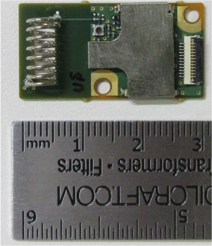
Click to zoom
Application Details
- Equipment Class
- DXX - Part 15 Low Power Communication Device Transmitter
- Date of Grant
- Nov 23, 2022
- Application Purpose
- Original Equipment
- Date of Application
- Nov 23, 2022
- Equipment Note
- Z-Wave Module
- Frequency Range
- 908.40000000 - 916.00000000
- Company
- Canon Inc.
- Country
- Japan
Documents & Files
Document Text
Text extracted from the exhibit documents filed with the FCC. Open a document above to read the original.
Users Manual
For the module installation to host systems, please follow the instruction below. 1. Insert the FPCor FFCinto the connector on the board. The contact of the connector is the bottom contact (board side).Please refer Pin Configuration (Page 5) to the circuit diagram for the pin arrangement of the connector. 2. Align the two holes on the board with the two holes on the main unit side. 3. Tighten the board and the main body together using two screws. Use M2 screws for the screws. This is a user manual for host product manufacturers to use when integrating the module in a host product. The device shall be installed as described above and is designed to use an integrated antenna. Do not modify the antenna or any other part of the module. Any modifications will invalidate the modular certifications and require new approvals for the host system. This device complies with below part 15 of the FCC Rules. Part 15 Subpart C The modular transmitter is only FCC authorized for the specific rule parts (i.e., FCC transmitter rules) listed on the grant (FCC Part 15.249), and the host product manufacturer is responsible for compliance to any other FCC rules that apply to the host not covered by the modular transmitter grant of certification. The final host product still requires Part 15 Subpart B compliance testing with the modular transmitter installed. FCC/ISED NOTICE Model:ZWAVEModule Model NCP04A, FCC ID: AZD249/IC:498J-249) This device complies with part 15 of FCC Rules and Industry Canada’s licence-exempt RSSs. Operation is subject to the following two conditions: (1)this device may not cause harmful interference, and (2) this device must accept any interference received, including interference that may cause undesired operation. Do not make any changes or modifications to the equipment unless otherwise specified in the manual. If such changes or modifications should be made, you could be required to stop operation of the equipment. FCC/ISED Notice for model: NCP04A The end product must be labeled “Contains FCC ID: AZD249” and “Contains ISED Certification Number: 498J-249” Following statement must be included in the user manual of host device. Specification General Operating Ratings ・ Operating ambient temperature range : -25C~65C 5%RH~90%RH ・ VDD operating supply voltage: 3.3V ± 10% (The wireless controller IC on the module has a built-in power regulator.) ・ Operating temperature range: -25C~65C RF Characteristics ・ Frequency Band : 902~930MHz ・ Channel : 1~3ch ・ Frequency : 908.40, 908.42, 916.00MHz ■ Pin Configuration FPC/FFC Connectors 0.5mm pitch 12pin Bottom contact
ID Label/Location Info
●①‘FCC ID:XXXXXYYY(§2.925) Permanently display the following FCC and Canada IDs with a character size of at least 4 points (Approx. 1.4 mm). NCP04A FCC ID: AZD249 IC: 498J-249 6mm Displayinthisrangeby laser printing. US/CA model NCP04A FCC ID: AZD249 IC: 498J-249
Test Report
Test report No. : 14486836S-B-R1 Page : 1 of 26 UL Japan, Inc. Shonan EMC Lab. 1-22-3 Megumigaoka, Hiratsuka-shi, Kanagawa-ken, 259-1220 Japan / +81-463-50-6400 RADIO TEST REPORT Test Report No.: 14486836S-B-R1 CustomerCanon Inc. Description of EUT Z-Wave Module Model Number of EUT NCP04A FCC ID AZD249 Test Regulation FCC Part 15 Subpart C Test Result Complied (Refer to SECTION 3) Issue Date November 16, 2022 Remarks- Representative test engineer Approved by Takahiro Kawakami Engineer Toyokazu Imamura Leader CERTIFICATE 1266.03 The testing in which "Non-accreditation" is displayed is outside the accreditation scopes in UL Japan, Inc. There is no testing item of "Non-accreditation". Report Cover Page - Form-U LID-003532 (DCS:13-EM-F0429) Issue# 21.0 Test report No. : 14486836S-B-R1 Page : 2 of 26 UL Japan, Inc. Shonan EMC Lab. 1-22-3 Megumigaoka, Hiratsuka-shi, Kanagawa-ken, 259-1220 Japan / +81-463-50-6400 ANNOUNCEMENT REVISION HISTORY Original Test Report No.: 14486836S-B Th is report is a revised version of 14486836S-B. 14486836S-B is replaced with this repor t. Revision Test Report No. Date Page Revised Contents - (Ori ginal) 14486836S-B November 10, 2022 - 1 14486836S-B-R1 November 16, 2022 Pag e 6 Corrected the description of “FCC Part 15.31 (e)” from: This EUT provides the stable voltage constantly to the host device. to: The RF Module has its own regulator. The RF Module is constantly provided with voltage through the regulator regardless of input voltage. Page 19 Corrected the title from: Radiated Emission (Electric Field Strength of Fundamental and Spurious Emission) to: Radiated Emission (Electric Field Strength of Spurious Emission) Th is test report shall not be reproduced in full or partial, without the written approval of UL Japan, In c. Th e results in this report appl y only to the sample tested. (Laboratory was not involved in sampling.) This sample tested is in compliance with the limits of the above re gulation. The test results in this test report are traceable to the national or international standa rds. Th is test report must not be used by the customer to claim product certification, approval, or endorsement by the A2LA accreditation bod y. This test re port covers Radio technical requirements. I t does not cover administrative issues such as Manual or non-Radio test related Requirements. (if applicab le) Th e all test items in this test report are conducted b y UL Japan, Inc. Shonan EMC Lab. The opinions and the interpretations to the result of the description in this report are outside scopes where UL Japan, Inc. has been accred ited. Th e information provided from the customer for this report is identified in Sectio n 1. For test report(s) referred in this report, the latest version (includin g any revisions) is always referred. Test report No. : 14486836S-B-R1 Page : 3 of 26 UL Japan, Inc. Shonan EMC Lab. 1-22-3 Megumigaoka, Hiratsuka-shi, Kanagawa-ken, 259-1220 Japan / +81-463-50-6400 Reference: Abbreviations (Including words undescribed in this report) A2LA The American Association for Laboratory Accreditation ICES Interference-Causing Equipment Standard AC Alternating Current IEC International Electrotechnical Commission AFH Adaptive Frequency Hopping IEEE Institute of Electrical and Electronics Engineers AM Amplitude Modulation IF Intermediate Frequency Amp, AMP Amplifier ILAC International Laboratory Accreditation Conference ANSI American National Standards Institute ISED Innovation, Science and Economic Development Canada Ant, ANT Antenna ISO International Organization for Standardization AP Access Point JAB Japan Accreditation Board ASK Amplitude Shift Keying LAN Local Area Network Atten., ATT Attenuator LIMS Laboratory Information Management System AV Average MCS Modulation and Coding Scheme BPSK Binary Phase-Shift Keying MRA Mutual Recognition Arrangement BR Bluetooth Basic Rate N/A Not Applicable BT Bluetooth NIST National Institute of Standards and Technology BT LE Bluetooth Low Energy NS No signal detect. BW BandWidth NSA Normalized Site Attenuation Cal Int Calibration Interval NVLAP National Voluntary Laboratory Accreditation Pro gram CCK Complementary Code Keying OBW Occupied Band Width Ch., CH Channel OFDM Orthogonal Frequency Division Multiplexing CISPR Comite International Special des Perturbations Radioelectri ques P/M Power meter CW Continuous Wave PCB Printed Circuit Board DBPSK Differential BPSK PER Packet Error Rate DC Direct Current PHY Physical Layer D-factor Distance factor PK Peak DFS Dynamic Frequency Selection PN Pseudo random Noise DQPSK Differential QPSK PRBS Pseudo-Random Bit Sequence DSSS Direct Sequence Spread Spectrum PSD Power Spectral Density EDR Enhanced Data Rate QAM Quadrature Amplitude Modulation EIRP, e.i.r.p. Equivalent Isotropically Radiated Power QP Quasi-Peak EMC ElectroMagnetic Compatibility QPSK Quadri-Phase Shift Keying EMI ElectroMagnetic Interference RBW Resolution Band Width EN European Norm RDS Radio Data System ERP, e.r.p. Effective Radiated Power RE Radio Equipment EU European Union RF Radio Frequency EUT Equipment Under Test RMS Root Mean Square Fac. Factor RSS Radio Standards Specifications FCC Federal Communications Commission Rx Receiving FHSS Frequency Hopping Spread Spectrum SA, S/A Spectrum Analyzer FM Frequency Modulation SG Signal Generator Freq. Frequency SVSWR Site-Voltage Standing Wave Ratio FSK Frequency Shift Keying TR Test Receiver GFSK Gaussian Frequency-Shift Keying Tx Transmitting GNSS Global Navigation Satellite System VBW Video BandWidth GPS Global Positioning System Vert. Vertical Hori. Horizontal WLAN Wireless LAN Test report No. : 14486836S-B-R1 Page : 4 of 26 UL Japan, Inc. Shonan EMC Lab. 1-22-3 Megumigaoka, Hiratsuka-shi, Kanagawa-ken, 259-1220 Japan / +81-463-50-6400 CONTENTS PAGE SECTION 1: Customer information ꞏꞏꞏꞏꞏꞏꞏꞏꞏꞏꞏꞏꞏꞏꞏꞏꞏꞏꞏꞏꞏꞏꞏꞏꞏꞏꞏꞏꞏꞏꞏꞏꞏꞏꞏꞏꞏꞏꞏꞏꞏꞏꞏꞏꞏꞏꞏꞏꞏꞏꞏꞏꞏꞏꞏꞏꞏꞏꞏꞏꞏꞏꞏꞏꞏꞏꞏꞏꞏꞏꞏꞏꞏꞏꞏꞏ 5 SECTION 2: Equipment under test (EUT) ꞏꞏꞏꞏꞏꞏꞏꞏꞏꞏꞏꞏꞏꞏꞏꞏꞏꞏꞏꞏꞏꞏꞏꞏꞏꞏꞏꞏꞏꞏꞏꞏꞏꞏꞏꞏꞏꞏꞏꞏꞏꞏꞏꞏꞏ…
Text truncated - open the document above for the full version.
Test Setup Photos
Test report No. : 14486836S-B-R1 Page : 24 of 26 UL Japan, Inc. Shonan EMC Lab. 1-22-3 Megumigaoka, Hiratsuka-shi, Kanagawa-ken, 259-1220 Japan / +81-463-50-6400 APPENDIX 3: Photographs of test setup Conducted Emission Photo 1 Photo 2 Test report No. : 14486836S-B-R1 Page : 25 of 26 UL Japan, Inc. Shonan EMC Lab. 1-22-3 Megumigaoka, Hiratsuka-shi, Kanagawa-ken, 259-1220 Japan / +81-463-50-6400 Radiated Emission Front Front (zoom) Rear (Below 30 MHz Horizontal) Rear (Below 30 MHz Vertical) Rear (30 MHz - 1 GHz) Rear (Above 1 GHz) Test report No. : 14486836S-B-R1 Page : 26 of 26 UL Japan, Inc. Shonan EMC Lab. 1-22-3 Megumigaoka, Hiratsuka-shi, Kanagawa-ken, 259-1220 Japan / +81-463-50-6400 Pre-check of Worst Case Position X-axis Y-axis Z-axis End of Report
Contact Information
Applicant
Genta Sato(General Manager)
Technical Contact
UL Japan, Inc.Toyokazu Imamura
[email protected]81-463-50-6400
1-22-3 Megumigaoka, Hiratsuka-shi · Kanagawa-ken · Japan
Test Firm
UL Japan, Inc. SHONAN EMC LABORATORYAkio Hayashi
[email protected]81-463-50-6400
Technical Specifications
| # | Rule Parts | Frequency Range | Power Output |
|---|---|---|---|
| 1 | 15C | 908.4 MHz - 916 MHz | - |
Other Applications from Canon Inc.
AZD264
Jul 23, 2026Digital Camera
Equipment Class
DTS - Digital Transmission SystemAZD260
Dec 17, 2025Digital Camera
Equipment Class
DTS - Digital Transmission System
AZD248
Aug 11, 2024Wireless Module
Equipment Class
DTS - Digital Transmission SystemAZD323
Jul 22, 2024Wireless Module
Equipment Class
DTS - Digital Transmission SystemAZD250
Jun 09, 2024Wireless Microphone
Equipment Class
DTS - Digital Transmission System