AZDCH91108802.11b/g WLAN Module
Canon Inc.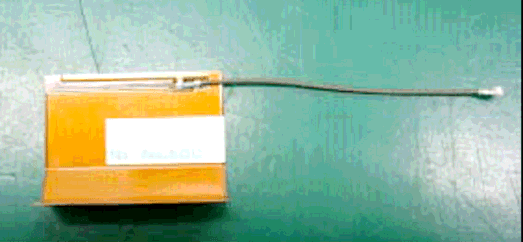
Click to zoom
Application Details
- Equipment Class
- DTS - Digital Transmission System
- Date of Grant
- Feb 25, 2007
- Application Purpose
- Original Equipment
- Date of Application
- Feb 25, 2007
- Equipment Note
- 802.11b/g WLAN Module
- Frequency Range
- 2412.00000000 - 2462.00000000
- Company
- Canon Inc.
- Country
- Japan
Documents & Files
Document Text
Text extracted from the exhibit documents filed with the FCC. Open a document above to read the original.
Users Manual
Wireless File Transmitter WFT-E2 WFT-E2A E INSTRUCTION MANUAL This product is offered in two versions, WFT-E2 and WFT-E2A. Each version operates on a different number of wireless LAN channels. The WFT-E2 can transmit on 13 channels, and the WFT-E2A, on 11 channels. This difference in the number of channels available is due to varying radio regulations in areas of use. In other respects, the WFT-E2 and WFT-E2A are identical. They are operated in the same way. This instruction manual describes operation using the WFT-E2 as an example. 2 Thank you for purchasing a Canon product. The Wireless File Transmitter WFT-E2 is an accessory for EOS-1D Mark III cameras (supporting wireless and wired LAN functions and equipped with a USB port). It enables the following operations. The WFT-E2 is compatible with IEEE 802.11b and IEEE 802.11g wireless LANs as well as 100 Base-TX Ethernet wired LANs. Wireless and Wired LAN Functions Functions When Connected via USB FTP PTP External Media GPS HTTP Transfer images to an FTP server Use a web browser to capture, view, and download images remotely Use EOS Utility to capture, view, and download images remotely Record, backup, or copy images onto external media Add information regarding the latitude, longitude, altitude, and date and time of shooting to images 3 Introduction These instructions should be followed only after your wireless or wired LAN and FTP server settings are complete. For details on configuring these settings, refer to the documentation provided with the respective equipment. Camera menu screens depicted in this manual are generally those of the EOS-1D Mark III. Terms in brackets [ ] indicate button or icon names or other software elements. Brackets also denote camera menu items. Page numbers in parentheses indicate where you can find additional information. Instructions on camera operations should be followed only after you have read the Camera Instruction Manual and are familiar with operating the camera. Sections of this manual labeled with the following symbols contain information of the corresponding nature. : Warnings to avoid potential problems are labeled with a caution symbol. : Supplemental information is labeled with a note symbol. Conventions Used in this Manual Windows is a trademark or registered trademark of Microsoft Corporation in the United States and other countries. Macintosh is a registered trademark of Apple Corporation in the United States and other countries. Wi-Fi is a registered trademark of the Wi-Fi Alliance. Wi-Fi Certified, WPA, WPA2, and the Wi-Fi Certified logo are trademarks of the Wi-Fi Alliance. UPnP is a trademark of the UPnP Implementers Corporation. All other corporate and brand names in this manual are trademarks or registered trademarks of their respective owners. Using the transmitter for remote image transfer, capture, or viewing requires adequate knowledge of configuring your wireless or wired LAN and FTP server. Canon cannot provide support for configuring wireless or wired LANs or FTP servers. Note that Canon cannot be held liable for any loss or damage to the transmitter from erroneous network or FTP server settings. In addition, Canon cannot be held liable for any other loss or damage caused by use of the transmitter. 4 Introduction Conventions Used in this Manual ...................................................................................................... 3 Areas of Use and Restrictions ........................................................................................................... 6 Safety Warnings................................................................................................................................. 7 Nomenclature..................................................................................................................................... 8 Attaching to the Camera .................................................................................................................... 9 Subsequent Organization of This Manual........................................................................................ 10 1Basic Network Settings 11 Displaying the Connection Wizard ................................................................................................... 12 Following the Connection Wizard .................................................................................................... 13 2FTP Settings and Image Transfer 19 Configuring FTP Transfer Settings .................................................................................................. 20 Automatic Image Transfer After Each Shot ..................................................................................... 22 Transferring Images Individually ...................................................................................................... 24 Batch Transfer ................................................................................................................................. 26 Checking Image Transfer History .................................................................................................... 31 Viewing Transferred Images ............................................................................................................ 32 3PTP Settings and Remote Capture 33 Configuring PTP Transfer Settings .................................................................................................. 34 Using EOS Utility ............................................................................................................................. 37 4HTTP Settings and Remote Capture 39 Configuring HTTP Transfer Settings................................................................................................ 40 Displaying WFT Server .................................................................................................................... 42 Shooting Remotely.............................................................…
Text truncated - open the document above for the full version.
External Photos
External Photo Canon Inc. WLAN MODULE UNIT [CH91108] FCC ID: AZDCH91108 Top Bottom Photo of Antenna Antenna 1 (Sansei Electric) Antenna 2 (Hitachi)
External Photos
FCC ID : AZDCH91108 IC number : 498C-CH91108 Model : CH91108 Applicant : Canon Inc. Photo for Limited Modular Approval letter A1 Photo(Modular transmitter) Shielding
ID Label/Location Info
Fig1. Dimension of Label Label is put on the top side of CH91108. On the bottom side, product number, CE mark and Company log mark are printed by slik screen. IC:498C-CH91108 FCC ID:AZDCH91108 007NY1234567 000085 123456 Fig.2 Top side of CH91108 Fig3. Bottom side of CH91108
Internal Photos
Internal Photo Canon Inc. WLAN MODULE UNIT [CH91108] FCC ID: AZDCH91108 Top
Operational Description
CH91108 WLAN MODULE UNIT Installation Manual The module has two deferent type of connectors for embedding. For embedding, the connectors are used for both mechanical and electrical connection. Power supply and control signals are provided via connector DF40C-50DS-0.4V made by Hirose located on bottom side of module in Fig.1. Fig.1 module outline (bottom view) A1 A2 A3 A4 A5 A6 A7 A8 A9 A10 A11 A12 A13 A14 A15 A16 A17 A18 A19 A20 A21 A22 A23 A24 A25 B1 B2 B3 B4 B5 B6 B7 B8 B9 B10 B11 B12 B13 B14 B15 B16 B17 B18 B19 B20 B21 B22 B23 B24 B25 DF40C-50DS- 0.4V Table 1 Pin Layout of DF40C-50DS-0.4V No. Pin Name I/O Type No. Pin Name I/O Type A1 GND - B1 GND - A2 D[15] I/O B2 D[14] I/O A3 D[13] I/O B3 D[12] I/O A4 D[11] I/O B4 D[10] I/O A5 D[9] I/O B5 D[8] I/O A6 D[7] I/O B6 D[6] I/O A7 D[5] I/O B7 D[4] I/O A8 D[3] I/O B8 D[2] I/O A9 D[1] I/O B9 D[0] I/O A10 GND - B10 GND - A11 A[9] I B11 A[10] I A12 A[7] I B12 A[8] I A13 A[5] I B13 A[6] I A14 A[3] I B14 A[4] I A15 A[1] I B15 A[2] I A16 GND - B16 A[0] I A17 PDn I B17 GND - A18 -CE[2] I B18 -CE[1] I A19 -IOWR I B19 -IORD I A20 -WE I B20 -OE I A21 RESET I B21 -IREQ O A22 -IOIS16 O B22 -WAIT O A23 GND - B23 GND - A24 VCC3.3 - B24 GND - A25 VCC3.3 - B25 GND - 2 antenna connectors (U.FL-R-SMT(10) by Hirose) are located on top side of module in Fig.2 IC:498C-CH91108 FCC ID:AZDCH91108 007NY1234567 000085 123456 The 2 antenna connectors are named ANT1 and ANT2 as shown in Fig.2. External antennas are connected to ANT1 or ANT2 or both via 50 Ohm Coaxial cable. When only one antenna is used, non-used connector can be kept open. ANT1 ANT2 Fig.2 module outline (top view) Fig.3 Example of Embedding FCC WARNING Changes or modifications not expressly approved by the party responsible for compliance could void the user’s authority to operate the equipment. NOTICE This transmitter must not be co-located or operated in conjunction with any other antenna or transmitter. This device complies with Part 15 of FCC Rules and RSS-Gen of IC Rules. Operation is subject to the following two conditions: (1) this device may not cause interference, and (2) this device must accept any interference, including interference that may cause undesired operation of this device. As well as above necessary FCC/IC statements, applicable RF Exposure statements are required for users manual of final product. [For Portable Use] Example of RF Exposure Statement for portable equipment: The available scientific evidence does not show that any health problems are associated with using low power wireless devices. There is no proof, however, that these low power wireless devices are absolutely safe. Low power Wireless devices emit low levels of radio frequency energy (RF) in the microwave range while being used. Whereas high levels of RF can produce health effects (by heating tissue), exposure to low-level RF that does not produce heating effects causes no known adverse health effects. Many studies of low-level RF exposures have not found any biological effects. Some studies have suggested that some biological effects might occur, but such findings have not been con- firmed by additional research. (Model Name of final product) has been tested and found to comply with FCC/IC radiation exposure limits set forth for an uncontrolled equipment and meets the FCC radio frequency (RF) Exposure Guidelines in Supplement C to OET65 and RSS-102 of the IC radio frequency (RF) Exposure rules. [For Mobile Use] This equipment complies with FCC/IC radiation exposure limits set forth for uncontrolled equipment and meets the FCC radio frequency (RF) Exposure Guidelines in Supplement C to OET65 and RSS-102 of the IC radio frequency (RF) Exposure rules. This equipment should be installed and operated with at least 20cm and more between the radiator and person’s body (excluding extremities: hands, wrists, feet and ankles). Declaration of conforming to R&TTE requirement Česky [Czech] CANON INC. tímto prohlašuje, že tento CH91108 je ve shodě se základními požadavky a dalšími příslušnými ustanoveními směrnice 1999/5/ES. Dansk [Danish] Undertegnede CANON INC. erklærer herved, at følgende udstyr CH91108 overholder de væsentlige krav og øvrige relevante krav i direktiv 1999/5/EF. Deutsch [German] Hiermit erklärt CANON INC., dass sich das Gerät CH91108 in Übereinstimmung mit den grundlegenden Anforderungen und den übrigen einschlägigen Bestimmungen der Richtlinie 1999/5/EG befindet. Eesti [Estonian] Käesolevaga kinnitab CANON INC. seadme CH91108 vastavust direktiivi 1999/5/EÜ põhinõuetele ja nimetatud direktiivist tulenevatele teistele asjakohastele sätetele. English Hereby, CANON INC., declares that this CH91108 is in compliance with the essential requirements and other relevant provisions of Directive 1999/5/EC. Español [Spanish] Por medio de la presente CANON INC. declara que el CH91108 cumple con los requisitos esenciales y cualesquiera otras disposiciones aplicables o exigibles de la Directiva 1999/5/CE. Ελληνική [Greek] ΜΕ ΤΗΝ ΠΑΡΟΥΣΑ CANON INC. ∆ΗΛΩΝΕΙ ΟΤΙCH91108 ΣΥΜΜΟΡΦΩΝΕΤΑΙ ΠΡΟΣ ΤΙΣ ΟΥΣΙΩ∆ΕΙΣ ΑΠΑΙΤΗΣΕΙΣ ΚΑΙ ΤΙΣ ΛΟΙΠΕΣ ΣΧΕΤΙΚΕΣ ∆ΙΑΤΑΞΕΙΣ ΤΗΣ Ο∆ΗΓΙΑΣ 1999/5/ΕΚ. Français [French] Par la présente CANON INC. déclare que l'appareil CH91108 est conforme aux exigences essentielles et aux autres dispositions pertinentes de la directive 1999/5/CE. Italiano [Italian] Con la presente CANON INC. dichiara che questo CH91108 è conforme ai requisiti essenziali ed alle altre disposizioni pertinenti stabilite dalla direttiva 1999/5/CE. Latviski [Latvian] Ar šo CANON INC. deklarē, ka CH91108 atbilst Direktīvas 1999/5/EK būtiskajām prasībām un citiem ar to saistītajiem noteikumiem. Lietuvių [Lithuanian] Šiuo CANON INC. deklaruoja, kad šis CH91108 atitinka esminius reikalavimus ir kitas 1999/5/EB Direktyvos nuostatas. Nederlands [Dutch] Hierbij verklaart CANON INC. dat het toestel CH91108 in overeenstemming is met de essentiële eisen en de andere relevante bepalingen van richtlijn 1999/5/EG. Malti [Maltese] Hawnhekk, CANON INC., jiddi…
Text truncated - open the document above for the full version.
RF Exposure Info
UL Apex Co., Ltd. Head Office EMC Lab. 4383-326 Asama-cho, Ise-shi, Mie-ken 516-0021 JAPAN Telephone : +81 596 24 8116 Facsimile : +81 596 24 8124 Applicant: CANON INC. Type of Equipment : WLAN MODULE UNIT Model No. : CH91108 FCC ID: AZDCH91108 CANON INC. declares that Model : CH91108 ⇒ complies with FCC radiation exposure requirement specified in the FCC Rules 2.1093(for portable)/2.1091 (for mobile). RF Exposure Calculations: ← The following information provides the minimum separation distance for the highest gain antenna provided with the “CH91108“ as calculate d from FCC OET Bulletin 65 Appendix A, Table (B) Limits for General Population / Uncontrolled Exposure. This calculation is based on the highest EIRP possible from the system, considering maximum power and antenna gain, and considering a 1.0mW/cm^2 uncontrolled exposure limit. The Friis formula used was: S = (P * G) / (4* π * r 2 ) Where P = 207.01 mW (Maximum peak output power) G = 1.66 Numerical Antenna gain; equal to 2.20 dBi r =20.0 cm For: CH91108S = 0.06835 mW/cm 2 No. : 27BE0338-HO-A-2 RF Exposure / SAR Statement
Test Report
Test report No. : 27BE0338-HO-A-2 Page : 2 of 73 Issued date : November 20, 2006 Revised date : February 13, 2007 FCC ID : AZDCH91108 UL Apex Co., Ltd. Head Office EMC Lab. 4383-326 Asama-cho, Ise-shi, Mie-ken 516-0021 JAPAN Telephone : +81 596 24 8116 Facsimile : +81 596 24 8124 MF060b(14.06.06) CONTENTS PAGE SECTION 1: Client information ....................................................................................................................3 SECTION 2: Equipment under test (E.U.T.)................................................................................................3 SECTION 3: Test specification, procedures & results.................................................................................4 SECTION 4: Operation of E.U.T. during testing .........................................................................................7 SECTION 5: Conducted Emission.................................................................................................................9 SECTION 6: Spurious Emission..................................................................................................................10 SECTION 7: Bandwidth ...............................................................................................................................11 SECTION 8: Maximum Peak Output Power .............................................................................................11 SECTION 9: Peak Power Density................................................................................................................11 APPENDIX 1: Photographs of test setup ....................................................................................................12 Conducted Emission.................................................................................................................................... 12 Spurious Emission (Radiated) .................................................................................................................... 13 Worst Case Position (Horizontal: Y-axis/ Vertical:Y-axis) ..................................................................... 14 APPENDIX 2: Data of EMI test....................................................................................................................15 Conducted Emission.................................................................................................................................... 15 Conducted Emission.................................................................................................................................... 17 6dB Bandwidth ............................................................................................................................................ 29 Maximum Peak OutPut Power .................................................................................................................. 32 Maximum Peak OutPut Power (Reference DATA) ................................................................................. 33 Radiated Spurious Emission (below 1GHz) .............................................................................................. 34 Conducted Spurious Emission.................................................................................................................... 60 Conducted emission Band Edge compliance............................................................................................. 67 Power Density .............................................................................................................................................. 68 99% Occupied Bandwidth .......................................................................................................................... 71 APPENDIX 3:Test instruments ....................................................................................................................73 Test report No. : 27BE0338-HO-A-2 Page : 3 of 73 Issued date : November 20, 2006 Revised date : February 13, 2007 FCC ID : AZDCH91108 UL Apex Co., Ltd. Head Office EMC Lab. 4383-326 Asama-cho, Ise-shi, Mie-ken 516-0021 JAPAN Telephone : +81 596 24 8116 Facsimile : +81 596 24 8124 MF060b(14.06.06) SECTION 1: Client information Company Name CANON INC. Brand name CANON Address 30-2, Shimomaruko 3-chome, Ohta-ku, Tokyo 146-8501,Japan Telephone Number +81-3-2757-6798 Facsimile Number +81-3-3757-8431 Contact Person Kuniaki Tanaka SECTION 2: Equipment under test (E.U.T.) 2.1 Identification of E.U.T. Type of Equipment WLAN MODULE UNIT Model No. CH91108 Serial No. 55, 58 Rating DC3.3V Country of Manufacture Japan Condition of EUT Production prototype (Not for Sale: This sample is equivalent to mass-produced items.) Receipt Date of Sample October 3, 2006 Modification of EUT No modification by the test lab. 2.2 Product Description Model No: CH91108 (referred to as the EUT in this report) is the Wireless LAN Module. Clock frequency in the system 40MHz Equipment Type Transceiver Frequency of Operation 2412-2462 MHz Bandwidth & Channel spacing 20MHz / 5MHz Type of Modulation DSSS / OFDM ITU code G1D, D1D Antenna type Ant.1: PCB Antenna Ant.2: Film Antenna Antenna Gain Ant.1: 2.2dBi / Ant.2: 1.7dBi Antenna port Antenna port 1 / Antenna port 2 Test report No. : 27BE0338-HO-A-2 Page : 4 of 73 Issued date : November 20, 2006 Revised date : February 13, 2007 FCC ID : AZDCH91108 UL Apex Co., Ltd. Head Office EMC Lab. 4383-326 Asama-cho, Ise-shi, Mie-ken 516-0021 JAPAN Telephone : +81 596 24 8116 Facsimile : +81 596 24 8124 MF060b(14.06.06) SECTION 3: Test specification, procedures & results 3.1 Test Specification Test Specification : FCC Part15 Subpart C : 2006 Title : FCC 47CFR Part15 Radio Frequency Device Subpart C Intentional Radiators Section 15.207 Conducted limits : 2006 Section 15.247 Operation within the bands 902-928MHz, 2400-2483.5MHz, and 5725-5850MHz : 2006 FCC 15.31 (e) The EUT is constantly provided the stable voltage (DC3.3V) from the limited ho…
Text truncated - open the document above for the full version.
Test Report
Test report No. : 27BE0338-HO-A-2 Page : 15 of 73 Issued date : November 20, 2006 Revised date : February 13, 2007 FCC ID : AZDCH91108 UL Apex Co., Ltd. Head Office EMC Lab. 4383-326 Asama-cho, Ise-shi, Mie-ken 516-0021 JAPAN Telephone : +81 596 24 8116 Facsimile : +81 596 24 8124 MF060b(14.06.06) APPENDIX 2: Data of EMI test Conducted Emission (11b/Low ch./Antenna1) DATA OF CONDUCTED EMISSION TEST UL Apex Co., Ltd. Head Office EMC Lab. No.4 Semi Anechoic Chamber Date : 2006/11/07 17:54:38 Applicant : CANON INC. Report No.:27BE0338-HO Kind of EUT: WLAN MODULE UNIT Power:DC3.3V Model No.: CH91108 Temp°C/Humi%:22deg.C / 62% Serial No.: 55 Operator:Motoya Imura Mode / Remarks : Transmitting 2412MHz, 11b, 11Mbps, ANT1 LIMIT : FCC15C §15.207 (QP)/ RSS-Gen / RSS-210 FCC15C §15.207 (AV)/ RSS-Gen / RSS-210 CHART:WITHOUT FACTOR,Peak hold data.Data is uncorrected. Except for the above table : adequate margin data below the limits. Frequency[Hz] [dBuV] << QP/AV DATA N :QP :AV .15M 30M .2M.3M .5M .7M1M2M3M5M7M10M20M 0 10 20 30 40 50 60 70 80 Frequency[Hz] [dBuV] << QP/AV DATA L :QP :AV .15M 30M .2M.3M .5M .7M1M2M3M5M7M10M20M 0 10 20 30 40 50 60 70 80 Test report No. : 27BE0338-HO-A-2 Page : 16 of 73 Issued date : November 20, 2006 Revised date : February 13, 2007 FCC ID : AZDCH91108 UL Apex Co., Ltd. Head Office EMC Lab. 4383-326 Asama-cho, Ise-shi, Mie-ken 516-0021 JAPAN Telephone : +81 596 24 8116 Facsimile : +81 596 24 8124 MF060b(14.06.06) Conducted Emission (11b/Mid ch./Antenna1) DATA OF CONDUCTED EMISSION TEST UL Apex Co., Ltd. Head Office EMC Lab. No.4 Semi Anechoic Chamber Date : 2006/11/07 18:01:01 Applicant : CANON INC. Report No.:27BE0338-HO Kind of EUT : Power:DC3.3V Model No.: CH91108 Temp°C/Humi%:22deg.C / 62% Serial No.: 55 Operator:Motoya Imura Mode / Remarks : Transmitting 2437MHz, 11b, 11Mbps, ANT1 LIMIT : FCC15C §15.207 (QP)/ RSS-Gen / RSS-210 FCC15C §15.207 (AV)/ RSS-Gen / RSS-210 CHART:WITHOUT FACTOR,Peak hold data.Data is uncorrected. Except for the above table : adequate margin data below the limits. Frequency[Hz] [dBuV]<< QP/AV DATA >>L:QP :AV N:QP :AV .15M 30M .2M.3M .5M .7M1M2M3M5M7M10M20M 0 10 20 30 40 50 60 70 80 Frequency Reading Level Reading Level Corr. ResultsResultsLimitLimitMarginMargin Phase Frequency QP AV Factor QPAVQPAVQPAVPhase [MHz][dBuV] [dBuV] [dB] [dBuV][dBuV][dBuV][dBuV][dB][dB] Phase 0.15940 61.0 52.1 0.161.152.265.555.54.43.3N 0.31830 47.9 38.8 0.248.139.059.849.811.710.8N 0.96830 39.3 32.3 0.339.632.656.046.016.413.4N 4.84400 36.3 26.2 0.536.826.756.046.019.219.3N 6.03880 48.7 34.3 0.649.334.960.050.010.715.1N 19.48100 40.1 29.2 1.541.630.760.050.018.419.3N 0.16120 60.4 50.4 0.160.550.565.455.44.94.9L 0.31811 45.1 35.1 0.245.335.359.849.814.514.5L 0.96610 36.1 28.3 0.336.428.656.046.019.617.4L 4.81700 35.1 27.3 0.535.627.856.046.020.418.2L 5.85100 44.6 33.1 0.645.233.760.050.014.816.3L 19.78000 39.7 28.8 1.541.230.360.050.018.819.7L WLAN MODULE UNIT Test report No. : 27BE0338-HO-A-2 Page : 17 of 73 Issued date : November 20, 2006 Revised date : February 13, 2007 FCC ID : AZDCH91108 UL Apex Co., Ltd. Head Office EMC Lab. 4383-326 Asama-cho, Ise-shi, Mie-ken 516-0021 JAPAN Telephone : +81 596 24 8116 Facsimile : +81 596 24 8124 MF060b(14.06.06) Conducted Emission (11b/High ch./Antenna1) DATA OF CONDUCTED EMISSION TEST UL Apex Co., Ltd. Head Office EMC Lab. No.4 Semi Anechoic Chamber Date : 2006/11/07 18:07:19 Applicant : CANON INC. Report No.:27BE0338-HO Kind of EUT: WLAN MODULE UNIT Power:DC3.3V Model No.: CH91108 Temp°C/Humi%:22deg.C / 62% Serial No.: 55 Operator:Motoya Imura Mode / Remarks : Transmitting 2462MHz, 11b, 11Mbps, ANT1 LIMIT : FCC15C §15.207 (QP)/ RSS-Gen / RSS-210 FCC15C §15.207 (AV)/ RSS-Gen / RSS-210 CHART:WITHOUT FACTOR,Peak hold data.Data is uncorrected. Except for the above table : adequate margin data below the limits. Frequency[Hz] [dBuV] << QP/AV DATA N :QP :AV .15M 30M .2M.3M .5M .7M1M2M3M5M7M10M20M 0 10 20 30 40 50 60 70 80 Frequency[Hz] [dBuV] << QP/AV DATA L :QP :AV .15M 30M .2M.3M .5M .7M1M2M3M5M7M10M20M 0 10 20 30 40 50 60 70 80 Test report No. : 27BE0338-HO-A-2 Page : 18 of 73 Issued date : November 20, 2006 Revised date : February 13, 2007 FCC ID : AZDCH91108 UL Apex Co., Ltd. Head Office EMC Lab. 4383-326 Asama-cho, Ise-shi, Mie-ken 516-0021 JAPAN Telephone : +81 596 24 8116 Facsimile : +81 596 24 8124 MF060b(14.06.06) Conducted Emission (11g/Low ch./Antenna1) DATA OF CONDUCTED EMISSION TEST UL Apex Co., Ltd. Head Office EMC Lab. No.4 Semi Anechoic Chamber Date : 2006/11/07 18:17:37 Applicant : CANON INC. Report No.:27BE0338-HO Kind of EUT: WLAN MODULE UNIT Power:DC3.3V Model No.: CH91108 Temp°C/Humi%:22deg.C / 62% Serial No.: 55 Operator:Motoya Imura Mode / Remarks : Transmitting 2412MHz, 11g, 54Mbps, ANT1 LIMIT : FCC15C §15.207 (QP)/ RSS-Gen / RSS-210 FCC15C §15.207 (AV)/ RSS-Gen / RSS-210 CHART:WITHOUT FACTOR,Peak hold data.Data is uncorrected. Except for the above table : adequate margin data below the limits. Frequency[Hz] [dBuV] << QP/AV DATA N :QP :AV .15M 30M .2M.3M .5M .7M1M2M3M5M7M10M20M 0 10 20 30 40 50 60 70 80 Frequency[Hz] [dBuV] << QP/AV DATA L :QP :AV .15M 30M .2M.3M .5M .7M1M2M3M5M7M10M20M 0 10 20 30 40 50 60 70 80 Test report No. : 27BE0338-HO-A-2 Page : 19 of 73 Issued date : November 20, 2006 Revised date : February 13, 2007 FCC ID : AZDCH91108 UL Apex Co., Ltd. Head Office EMC Lab. 4383-326 Asama-cho, Ise-shi, Mie-ken 516-0021 JAPAN Telephone : +81 596 24 8116 Facsimile : +81 596 24 8124 MF060b(14.06.06) Conducted Emission (11g/Mid ch./Antenna1) DATA OF CONDUCTED EMISSION TEST UL Apex Co., Ltd. Head Office EMC Lab. No.4 Semi Anechoic Chamber Date : 2006/11/07 18:22:49 Applicant : CANON INC. Report No.:27BE0338-HO Kind of EUT: WLAN MODULE UNIT Power:DC3.3V Model No. : CH91108 Temp°C/Humi%:22deg.C / 62% Serial No.: 55 Operator:Motoya Imura Mode / Remarks : Transmitting 2437MHz, 11g, 54Mbps, ANT1 LIMIT : FCC15C §15.207 (QP)/ RSS-Gen / RSS-210 FCC15C §15.207 (AV)/ RSS-Gen / RSS-210 CHART:WITHOUT FACTOR,Pea…
Text truncated - open the document above for the full version.
Test Report
Test report No. : 26LE0212-HO-A-2 Page : 2 of 91 FCC ID : AZDCH91108 Issued date : February 5, 2007 Revised date : February 13, 2007 UL Apex Co., Ltd. Head Office EMC Lab. 4383-326 Asama-cho, Ise-shi, Mie-ken 516-0021 JAPAN Telephone: +81 596 24 8116 Facsimile: +81 596 24 8124 CONTENTS PAGE SECTION 1 : Client information............................................................................................................................................ 3 SECTION 2 : Equipment under test (E.U.T.)........................................................................................................................ 3 2.1 Identification of E.U.T. ...................................................................................................................................... 3 2.2 Product Description ............................................................................................................................................ 4 SECTION 3 : Test standard information............................................................................................................................... 5 3.1 Requirements for compliance testing defined by the FCC ................................................................................. 5 3.2 Exposure limit .................................................................................................................................................... 6 SECTION 4 : Test result ......................................................................................................................................................... 7 4.1 Outline of test ..................................................................................................................................................... 7 4.1 Result of Max. SAR value .................................................................................................................................. 7 4.2 Test Location ...................................................................................................................................................... 7 SECTION 5 : Operation of E.U.T. during testing................................................................................................................. 8 5.1 Confirmation before SAR testing ....................................................................................................................... 8 5.2 Confirmation after SAR testing .......................................................................................................................... 8 5.3 Operating modes for SAR testing ....................................................................................................................... 8 5.4 Test setup of EUT............................................................................................................................................... 10 SECTION 6 : Test surrounding.............................................................................................................................................. 11 6.1 Measurement uncertainty ................................................................................................................................... 11 SECTION 7 : Confirmation before/after testing ................................................................................................................... 12 7.1 Conducted power before..................................................................................................................................... 12 7.2 Reference data of SAR test (Data rate determing).............................................................................................. 13 SECTION 8 : Measurement results........................................................................................................................................ 14 8.1 Body SAR 2450MHz ......................................................................................................................................... 14 8.2 Head SAR 2450MHz.......................................................................................................................................... 15 …
Text truncated - open the document above for the full version.
Contact Information
Applicant
Genta Sato(General Manager)
Technical Contact
Non-Technical Contact
UL ApexKeijiro Kumagai
[email protected]81-596-24-8116
Test Firm
UL Japan, Inc.Mitsuru Fujimura
Technical Specifications
| # | Rule Parts | Frequency Range | Power Output |
|---|---|---|---|
| 1 | 15C | 2.41 GHz - 2.46 GHz | 210.00 mW |
Other Applications from Canon Inc.
AZD264
Jul 23, 2026Digital Camera
Equipment Class
DTS - Digital Transmission SystemAZD260
Dec 17, 2025Digital Camera
Equipment Class
DTS - Digital Transmission System
AZD248
Aug 11, 2024Wireless Module
Equipment Class
DTS - Digital Transmission SystemAZD323
Jul 22, 2024Wireless Module
Equipment Class
DTS - Digital Transmission SystemAZD250
Jun 09, 2024Wireless Microphone
Equipment Class
DTS - Digital Transmission System