AZDFM33490FM33490
Canon Inc.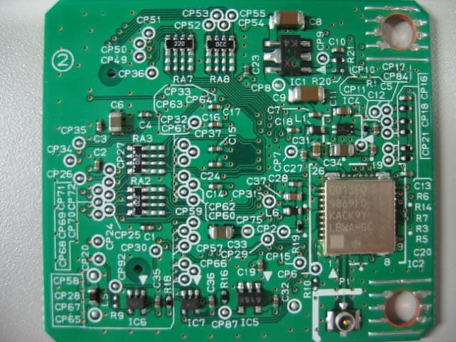
Click to zoom
Application Details
- Equipment Class
- DTS - Digital Transmission System
- Date of Grant
- Sep 17, 2007
- Application Purpose
- Original Equipment
- Date of Application
- Sep 03, 2007
- Equipment Note
- FM33490
- Frequency Range
- 2412.00000000 - 2462.00000000
- Company
- Canon Inc.
- Country
- Japan
Documents & Files
Document Text
Text extracted from the exhibit documents filed with the FCC. Open a document above to read the original.
Users Manual
1/1 Legal Notices FCC (Federal Communications Commission) Note: This equipment has been tested and found to comply with the limits for a Class A digital device, pursuant to Part 15 of the FCC Rules, and the limits for an ISM equipment, pursuant to Part 18 of the FCC Rules. These limits are designed to provide reasonable protection against harmful interference when the equipment is operated in a commercial environment. This equipment generates, uses, and can radiate, radio frequency energy and, if not installed and used in accordance with the Operator's Manual, may cause harmful interference to radio communications. Operation of this equipment in a residential area is likely to cause harmful interference in which case the user will be required to correct the interference at his own expense. Use of shielded cables are required to comply with Class A limits in Subpart B of Part 15 of the FCC Rules. Do not make any changes or modifications to the equipment unless otherwise specified in the manual. If you make such changes or modifications, you could be required to stop operation of the equipment. If your equipment malfunctions, please contact your local authorized Canon dealer from whom you purchased the equipment (if under warranty), or with whom you have a servicing contract. If you are not sure who to contact, and have both purchased and are using the equipment in the U.S.A., please refer to the "SUPPORT" page on Canon U.S.A.'s Web site (http://www.usa.canon.com). This transmitter must not be co-located or operated in conjunction with any other antenna or transmitter. This device complies with Part 15 of FCC Rules and RSS-Gen of IC Rules. Operation is subject to the following two conditions: (1) this device may not cause interference, and (2) this device must accept any interference, including interference that may cause undesired operation of this device. This equipment complies with FCC/IC radiation exposure limits set forth for uncontrolled equipment and meets the FCC radio frequency (RF) Exposure Guidelines in Supplement C to OET65 and RSS-102 of the IC radio frequency (RF) Exposure rules. This equipment should be installed and operated with at least 20cm and more between the radiator and person’s body (excluding extremities: hands, wrists, feet and ankles). User's Guide Wireless LAN Board NB-W1 Please read this guide before operating this product. After you finish reading this guide, store it in a safe place for future reference. Users in the European Union and other European countries WEEE Directive European Union (and EEA) only. This symbol indicates that this product is not to be disposed of with your household waste, according to the WEEE Directive (2002/96/EC) and your national law. This product should be handed over to a designated collection point, e.g., on an authorized one-for-one basis when you buy a new similar product or to an authorized collection site for recycling waste electrical and electronic equipment (EEE). Improper handling of this type of waste could have a possible negative impact on the environment and human health due to potentially hazardous substances that are generally associated with EEE. At the same time, your cooperation in the correct disposal of this product will contribute to the effective usage of natural resources. For more information about where you can drop off your waste equipment for recycling, please contact your local city office, waste authority, approved WEEE scheme or your household waste disposal service. For more information regarding return and recycling of WEEE products, please visit www.canon-europe.com/environment. (EEA: Norway, Iceland and Liechtenstein) European Radio Approval Information (for products fitted with Euapproved radio devices) This Product is a printer; low power, Radio LAN type devices (radio frequency (RF) wireless communication devices), operating in the 2.4 GHz band, may be embedded in your printer system which is intended for office use. This section is only applicable if these devices are present. Refer to the system label to verify the presence of wireless devices. Wireless devices that may be in your system are only qualified for use in the European Union or associated areas if a CE mark with a Notified Body Registration Number and the Alert Symbol is on the system label. The power output of the wireless device or devices that may be embedded in you printer is well below the RF exposure limits as set by the European Commission through the R&TTE directive. Regulatory Compliance Statements Low power, Radio LAN type devices (radio frequency (RF) wireless communication devices), operating in the 2.4 GHzGHz Band, may be embedded in your printer system. The following section is a general overview of considerations while operating a wireless device. The equipment complies with the RF Exposure Requirement 1999/519/EC, Council Recommendation of 12 July 1999 on the limitation of exposure of the general public to electromagnetic fields (0 Hz to 300 GHz). vi Preface Thank you for purchasing a Canon product. The Wireless LAN Board NB-W1 is a product that enables you to wirelessly connect your Canon MFP (Color imageRUNNER/imageRUNNER/imagePRESS series) to a network. This document describes the procedure for connecting a machine that includes the Wireless LAN Board NB-W1 to a network. Please read this manual thoroughly before operating the product to familiarize yourself with its capabilities, and to make the most of its many functions. After reading this manual, store it in a safe place for future reference. How To Use This Manual Symbols Used in This Manual The following symbols are used in this manual to explain procedures, restrictions, handling precautions, and instructions that should be observed for safety. CAUTION Indicates a caution concerning operations that may lead to injury to persons, or damage to property if not performed correctly. To use the machine safely, always pay attention to these cautions. IMPORTANT I…
Text truncated - open the document above for the full version.
Cover Letter(s)
American Telecommunications Certification Body Inc. 6731 Whittier Ave, McLean, VA 22101 September 4, 2007 RE: ATCB005369 FCC ID: AZDFM33490_ I have a few comments on this application. Depending on your responses, kindly understand there may be additional comments. 1. We must have separate Exhibits for both External Photos and Internal Photos. May I suggest that you provide one set with the RF shielding on and call it “External Photos”, and a second exhibit with RF shielding removed and reference “Internal Photos”. In addition, we will need photos of the underside of the RF module daughterboard. These photos must all be very clear. The ones you have already supplied are insufficient in detail. 2. We have no views of the antenna to be used with this Part 15 device. In general, the FCC considers an antenna a critical component and desires to have photographs of all antennas. 3. This product will be installed within various printers and restricted to specific Cannon models. This means that a Limited Modular Approval (LMA) is appropriate for this filing. Please provide the 8- point letter required for all Part 15 modular requests. Be sure to specify the hosts into which this transmitter will be installed 4. Please provide a more complete example manual for this product. You are reminded that the language of 15.21 and 15.19 must appear within the manual in addition to RF exposure statements. 5. Please note that for FCC work, the switching power supply must be on the ground plane, not on the tabletop. Please review and if needed confirm your radiated results. 6. The Operational Description indicates that this device can utilize WiFi channels 1 to 13. Only channels 1 to 11 are legal in North America. End users must not change channels to include those used outside USA. 7. You have included label Exhibits for module, extension card, and multifunction printer. I am confused – where and how will these different labels be used? 8. The applicable standards shown on IC application form are RSS 210 issue 6 and RSS-Gen issue Please correct them. ~~~~~~~~~~~~~~~~~~~~~~~~~~~~~~ ~ George Chen ~ mailto:[email protected] ~ Taiwan Mobile: +886 930600123 ~ SKYPE: georgeshirley ~~~~~~~~~~~~~~~~~~~~~~~~~~~~~~ The items indicated above must be submitted before processing can continue on the above referenced application. Failure to provide the requested information may result in application termination. Correspondence should be considered part of the permanent submission and may be viewed from the Internet after a Grant of Equipment Authorization is issued. Please do not respond to this correspondence using the email reply button. In order for your response to be processed expeditiously, you must submit your documents through the AmericanTCB.com website. Also, please note that partial responses increase processing time and should not be submitted. Any questions about the content of this correspondence should be directed to the sender.
External Photos
pictures of the module, FM33490 top view bottom view with the RF shield bottom view without the RF shield 12.0mm 1 2 . 0 m m label 005WWCA0009 FCC ID:AZDFM33490 0125 IC:498D-FM33490 CANON INC. Made in Japan FM33490
ID Label/Location Info
FM33490 Label . Intention of use of the product. The final installation of the product will be restricted to host such as Canon printers / multifunction printers (so far Model name : XXXX and YYYY) and OEM products. FM33490 Included Included FCC ID:AZDFM33490 Included IC:498D-FM33490 0125 CANON INC. Made in Japan 25mm×25mm 30mm×130mm final product(multifunction printer). extension card/ final product(printer). 005WWCA0009 FCC ID:AZDFM33490 0125 IC:498D-FM33490 CANON INC. Made in Japan FM33490 12mm×12mm module Included FCC ID:AZDFM33490 Included IC:498D-FM33490 FM33490
Test Report
Test report No. : 28AE0101-HO-A Page : 2 of 85 Issued date : August 24, 2007 FCC ID : AZDFM33490 UL Japan, Inc. Head Office EMC Lab. 4383-326 Asama-cho, Ise-shi, Mie-ken 516-0021 JAPAN Telephone : +81 596 24 8116 Facsimile : +81 596 24 8124 CONTENTS PAGE SECTION 1: Client information ............................................................................................................ 3 SECTION 2: Equipment under test (E.U.T.)........................................................................................ 3 SECTION 3: Test specification, procedures & results......................................................................... 4 SECTION 4: Operation of E.U.T. during testing .................................................................................7 SECTION 5: Conducted Emission......................................................................................................... 9 SECTION 6: Spurious Emission.......................................................................................................... 10 SECTION 7: Bandwidth ....................................................................................................................... 11 SECTION 8: Maximum Peak Output Power ..................................................................................... 11 SECTION 9: Peak Power Density........................................................................................................ 11 APPENDIX 1: Photographs of test setup ............................................................................................ 12 Conducted Emission ........................................................................................................12 Spurious Emission (Radiated) ........................................................................................13 Worst Case of Antenna Angle (Horizontal: 90 deg. / Vertical:0 deg.)........................14 Worst Case Position (Horizontal: X-axis/ Vertical:Y-axis.) ........................................15 APPENDIX 2: Data of EMI test............................................................................................................ 16 Conducted Emission ........................................................................................................16 6dB Bandwidth.................................................................................................................33 Maximum Peak Output Power.......................................................................................36 Radiated Spurious Emission (below 1GHz) ..................................................................38 Radiated Spurious Emission (above 1GHz) ..................................................................54 Conducted Spurious Emission........................................................................................70 Conducted emission Band Edge compliance .................................................................78 Power Density...................................................................................................................79 99%Occupied Bandwidth ...............................................................................................82 APPENDIX 3:Test instruments ............................................................................................................ 84 Test report No. : 28AE0101-HO-A Page : 3 of 85 Issued date : August 24, 2007 FCC ID : AZDFM33490 UL Japan, Inc. Head Office EMC Lab. 4383-326 Asama-cho, Ise-shi, Mie-ken 516-0021 JAPAN Telephone : +81 596 24 8116 Facsimile : +81 596 24 8124 SECTION 1: Client information Company Name : Canon Inc. Address : 7-5-1 Hakusan, Toride-shi, Ibaraki 302-8501, Japan Telephone Number : +81-297-74-2111 Facsimile Number : +81-297-73-7499 Contact Person : Masayuki Hiraide SECTION 2: Equipment under test (E.U.T.) 2.1 Identification of E.U.T. Type of Equipment : Wireless Module for Printer Model No. : FM33490 Serial No. : 10 Country of Manufacture : Japan Receipt Date of Sample : August 11, 2007 Condition of EUT : Production prototype (Not for Sale: This sample is equivalent to mass-produced items.) Modification of EUT : No modification by the test lab. 2.2 Product Description Model No: FM33490 (referred to as the EUT in this report) is the Wireless Module for Printer. The EUT is installed in the Printer (Model No.: LBP3460-US) manufactured by Canon Inc for testing purpose. Clock frequency(ies) in the system : 38.4MHz Equipment Type : Transceiver Frequency of Operation : 2412 – 2462MHz Modulation : DSSS, OFDM Operating Voltage : DC 3.3V (DC 3.13 – 3.46V) Antenna Type : Dipole antenna Antenna Gain : 1) SFP Antenna (Model No.: ANTB18-076A0): 2.14 dBi * SFP Antenna cannot rotate at 180 – 360 degree. 2) MFP Antenna (Model No.: FU-06-09-003): 2.0dBi * MFP Antenna has a cable. (Cable loss: 1.5dB) Test report No. : 28AE0101-HO-A Page : 4 of 85 Issued date : August 24, 2007 FCC ID : AZDFM33490 UL Japan, Inc. Head Office EMC Lab. 4383-326 Asama-cho, Ise-shi, Mie-ken 516-0021 JAPAN Telephone : +81 596 24 8116 Facsimile : +81 596 24 8124 SECTION 3: Test specification, procedures & results 3.1 Test Specification Test Specification : FCC Part15 Subpart C : 2007 Title : FCC 47CFR Part15 Radio Frequency Device Subpart C Intentional Radiators Section 15.207 Conducted limits Section 15.247 Operation within the bands 902-928MHz, 2400-2483.5MHz, and 5725-5850MHz FCC 15.31 (e) This EUT is constantly provided the stable voltage (DC3.3V) from the host device*. Therefore, this EUT complies with the requirement. FCC Part 15.203 Antenna requirement [SFP Antenna] The antenna is connected to the EUT with U.FL connector, and the installation is done by the professionals. Therefore, the equipment complies with the antenna requirement of Section 15.203. [MFP Antenna] The EUT has a unique coupling/antenna connector (model: MMCX-BJ-0. 4DV-CR, manufacturer: Amphenol). Therefore the equipment complies with the require…
Text truncated - open the document above for the full version.
Test Report
UL Japan, Inc. Head Office EMC Lab. 4383-326 Asama-cho, Ise-shi, Mie-ken 516-0021 JAPAN Telephone : +81 596 24 8116 Facsimile : +81 596 24 8124 Applicant: Canon Inc. Type of Equipment : Wireless Module for Printer Model No. : FM33490 FCC ID: AZDFM33490 Canon Inc. declares that Model : FM33490 ⇒ complies with FCC radiation exposure requirement specified in the FCC Rules 2.1093(for portable)/2.1091 (for mobile). RF Exposure Calculations: ← The following information provides the minimum separation distance for the highest gain antenna provided with the “FM33490“ as calculate d from FCC OET Bulletin 65 Appendix A, Table (B) Limits for General Population / Uncontrolled Exposure. This calculation is based on the highest EIRP possible from the system, considering maximum power and antenna gain, and considering a 1.0mW/cm^2 uncontrolled exposure limit. The Friis formula used was: S = (P * G) / (4* π * r 2 ) Where P = 138.68 mW (Maximum peak output power) G = 1.64 Numerical Antenna gain; equal 2.14 dBi r =20.0 cm For: FM33490S = 0.04516 mW/cm 2 No. : 28AE0101-HO-A RF Exposure / SAR Statement
Contact Information
Applicant
Genta Sato(General Manager)
Test Firm
UL Japan, IncMitsuru Fujimura
Technical Specifications
| # | Rule Parts | Frequency Range | Power Output |
|---|---|---|---|
| 1 | 15C | 2.41 GHz - 2.46 GHz | 138.00 mW |
Other Applications from Canon Inc.
AZD264
Jul 23, 2026Digital Camera
Equipment Class
DTS - Digital Transmission SystemAZD260
Dec 17, 2025Digital Camera
Equipment Class
DTS - Digital Transmission System
AZD248
Aug 11, 2024Wireless Module
Equipment Class
DTS - Digital Transmission SystemAZD323
Jul 22, 2024Wireless Module
Equipment Class
DTS - Digital Transmission SystemAZD250
Jun 09, 2024Wireless Microphone
Equipment Class
DTS - Digital Transmission System