AZDK30242802.11b/g Transmitter Module for Printer
Canon Inc.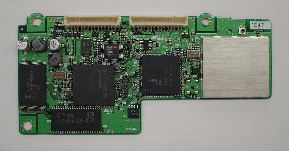
Click to zoom
Application Details
- Equipment Class
- DTS - Digital Transmission System
- Date of Grant
- Jul 28, 2004
- Application Purpose
- Original Equipment
- Date of Application
- Jul 28, 2004
- Equipment Note
- 802.11b/g Transmitter Module for Printer
- Frequency Range
- 2412.00000000 - 2462.00000000
- Company
- Canon Inc.
- Country
- Japan
Documents & Files
Document Text
Text extracted from the exhibit documents filed with the FCC. Open a document above to read the original.
External Photos
Front view Rear view External Photo K30242 CANON INC.
ID Label/Location Info
Label position of K30242 1.Label position Surface Side Reverse side ABCDEF GHIJKL Certification Label Serial No. Label 2.Label detail Certification Label 26mm 28mm Tolerance : ±0.5 Unit:mm Serial No. Label 20mm 11mm ABCDEF GHIJKL Serial No. Bar Code Tolerance : ±0.7 Unit:mm
Internal Photos
Front view Rear view External Photo K30242 CANON INC.
RF Exposure Info
UL Apex Co., Ltd. Head Office EMC Lab. 4383-326 Asama-cho, Ise-shi, Mie-ken 516-0021 JAPAN Telephone : +81 596 24 8116 Facsimile : +81 596 24 8124 Applicant: CANON INC. Type of Equipment : W ireless LAN module M odel No. : K30242 FCC ID: AZDK30242 RF Exposure Calculations: The follow ing inform ation provides the m inim um separation distance for the highest gain antenna provided with the “K30242“ as calculated from FCC OET Bulletin 65 Appendix A, Table (B) Limits for General Population / Uncontrolled Exposure. This calculation is based on the highest EIRP possible from the system, considering maximum power and antenna gain, and considering a 1.0mW /cm^2 uncontrolled exposure lim it. The Friis form ula used w as: S = (P * G) / (4* π * r 2 ) W here P = 60.54 mW (M aximum peak output power) G = 0.43 Numerical Antenna gain; equal -3.70 dBi r =20.0 cm For: K30242 S = 0.00514 mW/cm 2 No. : 24IE0043-HO-2 RF Exposure / SAR Statement
Test Report
Test report No. : 24IE0043-HO-2 Page : 2of70 Issued date : June 18, 2004 FCC ID : AZDK30242 UL Apex Co., Ltd. Head Office EMC Lab. 4383-326 Asama-cho, Ise-shi, Mie-ken 516-0021 JAPAN Telephone : +81 596 24 8116 Facsimile : +81 596 24 8124 MF060b(10.04.03) CONTENTS PAGE SECTION 1: Client information ..................................................................................................................... 3 SECTION 2: Equipment under test (E.U.T.)................................................................................................. 3 SECTION 3: Test specification, procedures & results ................................................................................ 4 SECTION 4: Operation of E.U.T. during testing ......................................................................................... 6 SECTION 5: Conducted Emission, Section 15.207 ...................................................................................... 9 SECTION 6: Spurious Emission 15.247(c).................................................................................................. 10 SECTION 7: Bandwidth, Section 15.247(a)(1)(2)....................................................................................... 11 SECTION 8: Maximum Peak Output Power, Section 15.247(b)(1)(3) ..................................................... 11 SECTION 9: Peak Power Density, Section 15.247 (d) ............................................................................... 11 APPENDIX 1: Photographs of test setup .................................................................................................... 12 Conducted Emission.........................................................................................................................................12 Worst Case Position (Z-axis:Horizontal / Y-axis:Vertical) ...........................................................................13 Spurious Emission (Radiated) .........................................................................................................................14 APPENDIX 2:Test instruments .................................................................................................................... 15 APPENDIX 3: Data of EMI test.................................................................................................................... 16 Conducted Emission(DSSS and other forms of modulation) ......................................................................16 6dB Bandwidth(DSSS and other forms of modulation)................................................................................23 Maximum Peak OutPut Power (DSSS and other forms of modulation) .....................................................26 Radiated Spurious Emission(DSSS and other forms of modulation) ..........................................................29 Conducted emission Band Edge compliance (DSSS and other forms of modulation) ...............................65 Power Density (DSSS and other forms of modulation ) ................................................................................66 Test report No. : 24IE0043-HO-2 Page : 3of70 Issued date : June 18, 2004 Revised date : July 1, 2004 FCC ID : AZDK30242 UL Apex Co., Ltd. Head Office EMC Lab. 4383-326 Asama-cho, Ise-shi, Mie-ken 516-0021 JAPAN Telephone : +81 596 24 8116 Facsimile : +81 596 24 8124 MF060b(10.04.03) SECTION 1: Client information Company Name : CANON INC. Brand name : CANON Address : 16-1, Shimonoge 3-chome, Takatsu-ku, Kawasaki-shi, Kanagawa, 213-8512 Japan Telephone Number : +81-44-811-2111 Facsimile Number : +81-44-814-2856 Contact Person : Kenji Kurita SECTION 2: Equipment under test (E.U.T.) 2.1 Identification of E.U.T. Type of Equipment : Wireless LAN module Model No. : K30242 Serial No. : 3(for Spurious Emission Radiated Test) 6(for Conducted Emission Test) 5(Except for Spurious Emission Radiated and Conducted Emission Test) Rating : DC 5V Country of Manufacture : Japan Receipt Date of Sample : March 12, 2004 Condition of EUT : Production prototype (Not for Sale: This sample is equivalent to mass-produced items.) 2.2 Product Description Model No: K30242 is the Wireless LAN module. The clock frequency of EUT is 12MHz(MCU), 40MHz (Wireless LAN chip) and 25MHz(LAN PHY chip). [W-LAN:IEEE802.11b,g] Equipment Type : Transceiver Frequency of operation : 2412-2462MHz Type of modulation : OFDM and DSSS Bandwidth & Channel spacing : 5MHz/ch Power control : No Mode of operation : Simplex Antenna Type : AH104F2450S1-T Antenna Gain : -3.7dBi(MAX) Antenna Connector Type : MICROWAVE COAXIAL CONNECTOR Method of Frequency Generation : Crystal Operating voltage (inner) : DC 5V Operating Temperature : 0 deg.C.-+50 deg.C. FCC 15.31 (e) This EUT provides stable voltage (the used voltage is regulated by IC) constantly to RF Module regardless of input voltage. Therefore, this EUT complies with the requirement. FCC Part 15.203 Antenna requirement The antenna is not removable from EUT. Therefore, the equipment complies with the antenna requirement of Section 15.203. Test report No. : 24IE0043-HO-2 Page : 4of70 Issued date : June 18, 2004 Revised date : July 1, 2004 FCC ID : AZDK30242 UL Apex Co., Ltd. Head Office EMC Lab. 4383-326 Asama-cho, Ise-shi, Mie-ken 516-0021 JAPAN Telephone : +81 596 24 8116 Facsimile : +81 596 24 8124 MF060b(10.04.03) SECTION 3: Test specification, procedures & results 3.1 Test Specification Test Specification : FCC Part15 Subpart C : 2003 Title : FCC 47CFR Part15 Radio Frequency Device Subpart C Intentional Radiators Section 15.207 Conducted limits(2003) Section 15.247 Operation within the bands 902-928MHz, 2400-2483.5MHz, and 5725-5850MHz(2003) 3.2 Procedures and results [DSSS and other forms of modulation ] No. Item Test Procedure Specification Remarks DeviationWorst margin Results 1 Conducted emission ANSI C63.4:2003 7. AC powerline conducted emission measurements Section 15.207 - N/A *See the worst margins(marked as shadin…
Text truncated - open the document above for the full version.
Test Setup Photos
Test report No. : 24IE0043-HO-2 Page : 12of70 Issued date : June 18, 2004 FCC ID : AZDK30242 UL Apex Co., Ltd. Head Office EMC Lab. 4383-326 Asama-cho, Ise-shi, Mie-ken 516-0021 JAPAN Telephone : +81 596 24 8116 Facsimile : +81 596 24 8124 MF060b(10.04.03) APPENDIX 1: Photographs of test setup Conducted Emission Front Rear Test report No. : 24IE0043-HO-2 Page : 13of70 Issued date : June 18, 2004 Revised date : July 1, 2004 FCC ID : AZDK30242 UL Apex Co., Ltd. Head Office EMC Lab. 4383-326 Asama-cho, Ise-shi, Mie-ken 516-0021 JAPAN Telephone : +81 596 24 8116 Facsimile : +81 596 24 8124 MF060b(10.04.03) Worst Case Position (Z-axis:Horizontal / Y-axis:Vertical) X-axis Y-axis Z-axis Test report No. : 24IE0043-HO-2 Page : 14of70 Issued date : June 18, 2004 Revised date : July 1, 2004 FCC ID : AZDK30242 UL Apex Co., Ltd. Head Office EMC Lab. 4383-326 Asama-cho, Ise-shi, Mie-ken 516-0021 JAPAN Telephone : +81 596 24 8116 Facsimile : +81 596 24 8124 MF060b(10.04.03) Spurious Emission (Radiated) Front Rear
Contact Information
Applicant
Genta Sato(General Manager)
Technical Contact
Non-Technical Contact
UL Apex Co., Ltd.Keijiro Kumagai
[email protected]81-596-24-8116
Test Firm
UL Apex Co., Ltd.Tetsuya Hashimoto
Technical Specifications
| # | Rule Parts | Frequency Range | Power Output |
|---|---|---|---|
| 1 | 15C | 2.41 GHz - 2.46 GHz | 60.50 mW |
Other Applications from Canon Inc.
AZD264
Jul 23, 2026Digital Camera
Equipment Class
DTS - Digital Transmission SystemAZD260
Dec 17, 2025Digital Camera
Equipment Class
DTS - Digital Transmission System
AZD248
Aug 11, 2024Wireless Module
Equipment Class
DTS - Digital Transmission SystemAZD323
Jul 22, 2024Wireless Module
Equipment Class
DTS - Digital Transmission SystemAZD250
Jun 09, 2024Wireless Microphone
Equipment Class
DTS - Digital Transmission System