AZDK30254Wireless LAN Module
Canon Inc.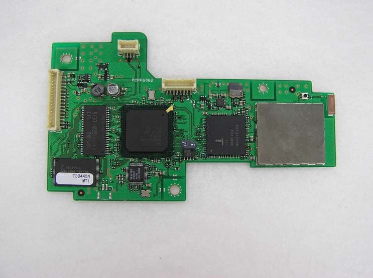
Click to zoom
Application Details
- Equipment Class
- DTS - Digital Transmission System
- Date of Grant
- Aug 21, 2005
- Application Purpose
- Original Equipment
- Date of Application
- Aug 21, 2005
- Equipment Note
- Wireless LAN Module
- Frequency Range
- 2412.00000000 - 2462.00000000
- Company
- Canon Inc.
- Country
- Japan
Documents & Files
Document Text
Text extracted from the exhibit documents filed with the FCC. Open a document above to read the original.
Users Manual
Photo Printer Quick Start Guide iP5200R_QSG_US.book Page i Friday, May 20, 2005 1:58 PM Canon PIXMA iP5200R Photo Printer Quick Start Guide. Copyright This manual is copyrighted by Canon U.S.A., Inc. with all rights reserved. Under the copyright laws, this manual may not be reproduced in any form, in whole or in part, without the prior written consent of Canon U.S.A., Inc. © 2005 Canon U.S.A., Inc. Disclaimer Canon U.S.A., Inc. has reviewed this manual thoroughly in order that it will be an easy-to-use guide to your Canon PIXMA iP5200R Photo Printer. All statements, technical information and recommendations in this manual and in any guides or related documents are believed reliable, but the accuracy and completeness thereof are not guaranteed or warranted, and they are not intended to be, nor should they be understood to be, representation or warranties concerning the products described. Specifications are subject to change without notice. As an ENERGY STAR partner, Canon U.S.A., Inc., has determined that this product meets the ENERGY STAR guidelines for energy efficiency. All information regarding non-Canon products was compiled from publicly available information. No representation is made regarding the accuracy thereof. Trademarks z“Windows” and “Internet Explorer” are trademarks of Microsoft Corporation, registered in the United States and other countries. z“Macintosh” and “Mac” are trademarks of Apple Computer, Inc., registered in the U.S. and other countries. z“Wi-Fi” is a registered trademark of the Wi-Fi Alliance. The “Wi-Fi CERTIFIED” logo is a certification mark of the Wi-Fi Alliance. Canon U.S.A., Inc. One Canon Plaza Lake Success, NY 11042 iP5200R_QSG_US.book Page ii Friday, May 20, 2005 1:58 PM Contents 1 Contents Basic Printing Turning on the Printer . . . . . . . . . . . . . . . . . . . . . . . . . . . . . . . . . . . . . . . . . . . . . . . . . . . . . . . . . . . . . 2 Turning off the Printer . . . . . . . . . . . . . . . . . . . . . . . . . . . . . . . . . . . . . . . . . . . . . . . . . . . . . . . . . . . . . 3 Loading Paper . . . . . . . . . . . . . . . . . . . . . . . . . . . . . . . . . . . . . . . . . . . . . . . . . . . . . . . . . . . . . . . . . . . 4 Using Specialty Media . . . . . . . . . . . . . . . . . . . . . . . . . . . . . . . . . . . . . . . . . . . . . . . . . . . . . . . . . . . 18 Printing with Windows . . . . . . . . . . . . . . . . . . . . . . . . . . . . . . . . . . . . . . . . . . . . . . . . . . . . . . . . . . . 20 Printing with Macintosh . . . . . . . . . . . . . . . . . . . . . . . . . . . . . . . . . . . . . . . . . . . . . . . . . . . . . . . . . . 23 Canceling Printing . . . . . . . . . . . . . . . . . . . . . . . . . . . . . . . . . . . . . . . . . . . . . . . . . . . . . . . . . . . . . . . 26 Advanced Printing Printing Photographs Directly from a PictBridge Compliant Device . . . . . . . . . . . . . . . . . . . . . . . 28 Accessing the Printer Driver (Windows) . . . . . . . . . . . . . . . . . . . . . . . . . . . . . . . . . . . . . . . . . . . . . 35 Using the Bundled Software . . . . . . . . . . . . . . . . . . . . . . . . . . . . . . . . . . . . . . . . . . . . . . . . . . . . . . . 36 Printing Maintenance Replacing an Ink Tank . . . . . . . . . . . . . . . . . . . . . . . . . . . . . . . . . . . . . . . . . . . . . . . . . . . . . . . . . . . . 37 When Printing Becomes Faint or Colors are Incorrect . . . . . . . . . . . . . . . . . . . . . . . . . . . . . . . . . . 46 Printing the Nozzle Check Pattern . . . . . . . . . . . . . . . . . . . . . . . . . . . . . . . . . . . . . . . . . . . . . . . . . . 47 Print Head Cleaning. . . . . . . . . . . . . . . . . . . . . . . . . . . . . . . . . . . . . . . . . . . . . . . . . . . . . . . . . . . . . . 52 Print Head Deep Cleaning . . . . . . . . . . . . . . . . . . . . . . . . . . . . . . . . . . . . . . . . . . . . . . . . . . . . . . . . . 56 Aligning the Print Head . . . . . . . . . . . . . . . . . . . . . . . . . . . . . . . . . . . . . . . . . . . . . . . . . . . . . . . . . . . 60 Troubleshooting Cannot Install the Printer Driver. . . . . . . . . . . . . . . . . . . . . . . . . . . . . . . . . . . . . . . . . . . . . . . . . . . . 65 Cannot Connect to PC Properly . . . . . . . . . . . . . . . . . . . . . . . . . . . . . . . . . . . . . . . . . . . . . . . . . . . . 66 Print Results Not Satisfactory or Contains Errors . . . . . . . . . . . . . . . . . . . . . . . . . . . . . . . . . . . . . . 67 Troubleshooting Printer Hardware. . . . . . . . . . . . . . . . . . . . . . . . . . . . . . . . . . . . . . . . . . . . . . . . . . 70 Paper Does Not Feed Properly . . . . . . . . . . . . . . . . . . . . . . . . . . . . . . . . . . . . . . . . . . . . . . . . . . . . . 72 Paper Jams . . . . . . . . . . . . . . . . . . . . . . . . . . . . . . . . . . . . . . . . . . . . . . . . . . . . . . . . . . . . . . . . . . . . . 73 Handling Error Messages . . . . . . . . . . . . . . . . . . . . . . . . . . . . . . . . . . . . . . . . . . . . . . . . . . . . . . . . . 77 An Error Message Appears on the Screen . . . . . . . . . . . . . . . . . . . . . . . . . . . . . . . . . . . . . . . . . . . . 79 Cannot Print Properly from the Digital Camera. . . . . . . . . . . . . . . . . . . . . . . . . . . . . . . . . . . . . . . . 82 Appendix Specifications . . . . . . . . . . . . . . . . . . . . . . . . . . . . . . . . . . . . . . . . . . . . . . . . . . . . . . . . . . . . . . . . . . 87 Safety Precautions . . . . . . . . . . . . . . . . . . . . . . . . . . . . . . . . . . . . . . . . . . . . . . . . . . . . . . . . . . . . . . 92 Regulatory Information . . . . . . . . . . . . . . . . . . . . . . . . . . . . . . . . . . . . . . . . . . . . . . . . . . . . . . . . . . . 94 CANON U.S.A., INC. LIMITED WARRANTY --- (USA Only). . . . . . . . . . . . . . . . . . . . . . . . . . . . . . . . . 95 Index. . . . . . . . . . . . . . . . . . . . . . . . . . . . . . . . . . . . . . . . . . . . . . . . . . . . . . . . . . . . . . …
Text truncated - open the document above for the full version.
Users Manual
Printing Maintenance 49 3Open the Canon IJ Printer Utility dialog box. (1) Select Applications from the Go menu, and then double-click the Utilities folder. (2) Double-click the Printer Setup Utility icon. When using Mac OS X v.10.2, double-click the Print Center icon. (3) Select the name of your printer from the Name list and click Utility. When using Mac OS X v.10.2, select the name of your printer from the Name list and click Configure. (4) Select the name of your printer from the Product list and click Maintenance. 4Print the Nozzle Check Pattern. (3) Read the message and click Print Check Pattern. The nozzle check pattern will be printed. Clicking Initial Check Items displays the items to be checked before printing the pattern. 5Examine the pattern and take the appropriate action. See “Examining the Nozzle Check Pattern” on page 50. (1) Select Test Print from the pop-up menu. (2) Click Nozzle Check. iP5200R_QSG_US.book Page 49 Friday, May 20, 2005 1:58 PM Printing Maintenance 50 Examining the Nozzle Check Pattern The nozzle check pattern should appear as follows when ink is discharged properly. Examine the nozzle check pattern output by the printer, and clean the Print Head when necessary. The nozzle check pattern will not be printed correctly if there is not enough ink. Replace the ink tank if the remaining amount of ink is insufficient. See “Replacing an Ink Tank” on page 37. 1Confirm the printed nozzle check pattern. (1) If line of this pattern are missing, the “Black” print head nozzle needs cleaning. Example: When line are missing (2) If these patterns have white stripes, the “Color” print head nozzle needs cleaning. Example: When white stripes appear (1) (2) iP5200R_QSG_US.book Page 50 Friday, May 20, 2005 1:58 PM Printing Maintenance 51 2When cleaning is necessary, click Cleaning on the Pattern Check dialog box. If you want to continue to clean the Print Head from here, go to step 3-(3) of the Windows or Macintosh Print Head Cleaning procedures as appropriate. See “Print Head Cleaning” on page 52. If no lines of the group (1) pattern are missing, and the group (2) patterns have no white stripes, click Exit or Quit. Nozzle Check Pattern examination finishes. iP5200R_QSG_US.book Page 51 Friday, May 20, 2005 1:58 PM Printing Maintenance 52 Print Head Cleaning Clean the Print Head if missing lines or white stripes appear in the nozzle check pattern. Note that cleaning the Print Head causes waste ink to be absorbed in the waste ink absorber. Cleaning the Print Head consumes ink, so perform Print Head Cleaning only when necessary. zEnsure that the Inner Cover is closed. Cleaning the Print Head Without a Computer zThe Print Head can also be cleaned from the printer itself. With the printer on, hold down the RESUME/CANCEL button until the POWER lamp flashes green once, and then release it immediately. The Print Head Cleaning dialog box of step 3-(3) is directly displayed when you click Cleaning on the Pattern Check dialog box. See “Examining the Nozzle Check Pattern” on page 50. 1Ensure that the printer is on. 2Open the printer properties dialog box. See “Opening the Printer Properties Dialog Box Directly from the Start Menu” on page 35. iP5200R_QSG_US.book Page 52 Friday, May 20, 2005 1:58 PM Printing Maintenance 53 3Start Print Head Cleaning. Print Head Cleaning starts when the POWER lamp starts blinking green. Do not perform any other operations until the Print Head Cleaning finishes. This takes about 50 seconds. (5) Read the message and click Print Check Pattern to print the nozzle check pattern. The nozzle check pattern is printed. Do not perform any other operations until the nozzle check pattern printing finishes. The nozzle check pattern will not be printed correctly if there is not enough ink. Replace the ink tank if the remaining amount of ink is insufficient. See “Replacing an Ink Tank” on page 37. (1) Click the Maintenance tab. (2) Click Cleaning. (3) Select the ink group to clean. When cleaning the nozzles of black ink tanks: select Black to clean the nozzles of PGI-5BK, Color to clean the nozzles of CLI-8BK. Clicking Initial Check Items displays the items to be checked before cleaning. (4) Click Execute. iP5200R_QSG_US.book Page 53 Friday, May 20, 2005 1:58 PM Printing Maintenance 54 4Check the Print Head condition with the printed nozzle check pattern. See “Examining the Nozzle Check Pattern” on page 50. If the problem remains after performing Print Head Cleaning twice, try Print Head Deep Cleaning. See “Print Head Deep Cleaning” on page 56. The Cleaning dialog box of step 3-(3) is directly displayed when you click Cleaning on the Pattern Check dialog box. See “Examining the Nozzle Check Pattern” on page 50. 1Ensure that the printer is on. 2Open the Canon IJ Printer Utility dialog box. (1) Select Applications from the Go menu, and then double-click the Utilities folder. (2) Double-click the Printer Setup Utility icon. When using Mac OS X v.10.2, double-click the Print Center icon. (3) Select the name of your printer from the Name list and click Utility. When using Mac OS X v.10.2, select the name of your printer from the Name list and click Configure. (4) Select the name of your printer from the Product list and click Maintenance. 3Start Print Head Cleaning. (1) Ensure that Cleaning is selected from the pop-up menu. (2) Click Cleaning. iP5200R_QSG_US.book Page 54 Friday, May 20, 2005 1:58 PM Printing Maintenance 55 Print Head Cleaning starts when the POWER lamp starts blinking green. Do not perform any other operations until the Print Head Cleaning finishes. This takes about 50 seconds. (5) Read the message and click Print Check Pattern to print the nozzle check pattern. The nozzle check pattern is printed. Do not perform any other operations until the nozzle check pattern printing finishes. The nozzle check pattern will not be printed correctly if there is not enough ink. Replace the ink tank if the remaining amount of ink is insufficient. See “Replacing an Ink Tank”…
Text truncated - open the document above for the full version.
Cover Letter(s)
July 25, 2005 RE: FCC ID: AZDK30254_ATCB002623 Attention: Makoto Kosaka / Makoto Kosaka I have a few comments on this Application. Please note that further comments may arise in response to answers provided to the questions below. 1. Please remove the shield from the module and provide a phot of the circuitry underneath. 2. Please note that while the OEM installation manual (instructions) is not provided to the end user, it is not an item that can have permanent confidentiality. Please remove this item from the list of confidential material. If the instructions are desired to have temporary confidentiality, please include it on the temporary confidentiality request. Dennis Ward mailto:[email protected] The items indicated above must be submitted before processing can continue on the above referenced application. Failure to provide the requested information may result in application termination. Correspondence should be considered part of the permanent submission and may be viewed from the Internet after a Grant of Equipment Authorization is issued. Please do not respond to this correspondence using the email reply button. In order for your response to be processed expeditiously, you must submit your documents through the AmericanTCB.com website. Also, please note that partial responses increase processing time and should not be submitted. Any questions about the content of this correspondence should be directed to the sender.
External Photos
Photo CANON INC. WLAN Module for Printer Model: K30254 Top Bottom VCOPA TRANSCEIVER Shield inside photograph of BANZEE FUJITSU DEVICES CONFIDENTIAL TRANSCEIVERVCO PA FUJITSU DEVICES CONFIDENTIAL
ID Label/Location Info
Label position of K30254 1.Label position Certification Label Surface Side ************ Serial No. Label Reverse side 2.Label detail Certification Label 26mm 28mm Tolerance : ±0.5 Unit:mm Serial No. Label 14mm 11mm ABCDEF GHIJKL Serial No. Bar Code Tolerance : ±0.7 Unit:mm
Internal Photos
VCOPA TRANSCEIVER Shield inside photograph of BANZEE FUJITSU DEVICES CONFIDENTIAL TRANSCEIVERVCO PA FUJITSU DEVICES CONFIDENTIAL
RF Exposure Info
UL Apex Co., Ltd. Head Office EMC Lab. 4383-326 Asama-cho, Ise-shi, Mie-ken 516-0021 JAPAN Telephone : +81 596 24 8116 Facsimile : +81 596 24 8124 Applicant: CANON INC. Type of Equipment : W LAN module for printer M odel No. : K30254 FCC ID: AZDK30254 C A N O N IN C . declares that M odel : W LA N m odule for printer complies with FCC radiation exposure requirement specified in the FCC Rules 2.1091. The “K30254“ has 142.56 mW of conducted Peak Output power and 198.61 mW of EIRP. This kind of equipment is below 60/frequency[GHz] mW (TCB Exclusion List) so that SA R testing is excluded. The Follow ing calculation is the reference data for 20cm distance. RF Exposure Calculations: The follow ing inform ation provides the m inim um separation distance for the highest gain antenna provided w ith the “K 30254“ as calculated from FC C O ET Bulletin 65 A ppendix A , Table (B) Lim its for G eneral Population / U ncontrolled Exposure. This calculation is based on the highest EIRP possible from the system, considering maximum power and antenna gain, and considering a 1.0mW /cm^2 uncontrolled exposure lim it. The Friis form ula used w as: S = (P * G ) / (4* π * r 2 ) Where P = 142.56 mW (M aximum peak output power) G = 1.39 Numerical Antenna gain; equal 1.44 dBi r =20.0 cm For: K30254S = 0.03951 mW/cm 2 No. : 25IE0087-HO RF Exposure / SAR Statement
Test Report
Test report No. : 25IE0087-HO-1 Page : 2 of 49 Issued date : July 8, 2005 FCC ID : AZDK30254 UL Apex Co., Ltd. Head Office EMC Lab. 4383-326 Asama-cho, Ise-shi, Mie-ken 516-0021 JAPAN Telephone : +81 596 24 8116 Facsimile : +81 596 24 8124 MF060b(01.06.05) CONTENTS PAGE SECTION 1: Client information ......................................................................................................... 3 SECTION 2: Equipment under test (E.U.T.)..................................................................................... 3 SECTION 3: Test specification, procedures & results...................................................................... 5 SECTION 4: Operation of E.U.T. during testing .............................................................................. 7 SECTION 5: Conducted Emission...................................................................................................... 9 SECTION 6: Spurious Emission ....................................................................................................... 10 SECTION 7: 6dB Bandwidth ............................................................................................................ 11 SECTION 8: Maximum Peak Output Power .................................................................................. 11 SECTION 9: Peak Power Density..................................................................................................... 11 APPENDIX 1: Photographs of test setup .........................................................................................12 Conducted Emission .............................................................................................................................. 12 Spurious Emission (Radiated)............................................................................................................... 13 Worst Case Position (Z-axis:Horizontal / Z-axis:Vertical) ................................................................. 14 APPENDIX 2:Test instruments ......................................................................................................... 15 APPENDIX 3: Data of EMI test......................................................................................................... 16 Conducted Emission .............................................................................................................................. 16 6dB Bandwidth(DSSS and other forms of modulation)...................................................................... 17 Maximum Peak OutPut Power (DSSS and other forms of modulation) ........................................... 20 Radiated Spurious Emission(DSSS and other forms of modulation ) (below 1GHz)....................... 23 Radiated Spurious Emission(DSSS and other forms of modulation) (above 1GHz)........................ 29 Conducted Spurious Emission(DSSS and other forms of modulation) ............................................. 35 Conducted Spurious Emission(DSSS and other forms of modulation) ............................................. 38 Conducted emission Band Edge compliance (DSSS and other forms of modulation) ..................... 41 Power Density (DSSS and other forms of modulation )...................................................................... 42 99%Occupied Bandwidth(DSSS and other forms of modulation) .................................................... 45 APPENDIX 4: Reference data [Characteristic and destructive tests] ............................................ 47 Test report No. : 25IE0087-HO-1 Page : 3 of 49 Issued date : July 8, 2005 FCC ID : AZDK30254 UL Apex Co., Ltd. Head Office EMC Lab. 4383-326 Asama-cho, Ise-shi, Mie-ken 516-0021 JAPAN Telephone : +81 596 24 8116 Facsimile : +81 596 24 8124 MF060b(01.06.05) SECTION 1: Client information Company Name : CANON INC. Address : 451, Tsukagoshi 3-chome, Saiwai-ku, Kawasaki-shi, Kanagawa 212-8530, Japan Telephone Number : +81-44-542-0164 Facsimile Number : +81-44-542-7524 Contact Person : Keiji Kawata SECTION 2: Equipment under test (E.U.T.) 2.1 Identification of E.U.T. Type of Equipment : WLAN module for printer Model No. : K30254 Serial No. : 08F2E2 (Spurious Emission(Radiated) and Other tests) 08F2F2 (Conducted emission) Rating : DC3.35V(Operating)+/- 7 % , DC1.8V,2.9V,3.3V(Inner) Country of Manufacture : Japan Receipt Date of Sample : May 30, 2005 Condition of EUT : Production prototype (Not for Sale: This sample is equivalent to mass-produced items.) Test report No. : 25IE0087-HO-1 Page : 4 of 49 Issued date : July 8, 2005 FCC ID : AZDK30254 UL Apex Co., Ltd. Head Office EMC Lab. 4383-326 Asama-cho, Ise-shi, Mie-ken 516-0021 JAPAN Telephone : +81 596 24 8116 Facsimile : +81 596 24 8124 MF060b(01.06.05) 2.2 Product Description Model No: K30254 (referred to as the EUT in this report) is IEEE802.11b/g Wireless LAN module for printer. FCC 15.31 (e) Power source, DC3.35V of EUT is supplied from the printer in which the EUT is installed. The following three voltages are supplied with RF module part. - 3.3V (not regulated) - 2.9V (regulated) - 1.8V (regulated) Testing of the variation of the input power was performed and complied with this requirement. As for the detail, please refer to APPENDIX 4. FCC Part 15.203 Antenna requirement The antenna is not removable from EUT. Therefore the equipment complies with the antenna requirement of Section 15.203. IEEE802.11b/g Wireless LAN Equipment Type Transceiver Frequency band Lower limit 2412MHz Upper limit 2462MHz Channel spacing 5MHz Type of Modulation DSSS/OFDM Clock frequency in the system MCU:12MHz, WLAN chip: 40MHz, LAN PHY chip: 25MHz Antenna Type Chip Dielectric Antenna Antenna Connector Type Microwave Coaxial Connector Antenna Gain 1.44 dBi max Mode of Operation Simplex ITU code G1D Power Supply DC3.35V(Operating)+/- 7% DC1.8V,2.9V,3.3V(Inner) Test report No. : 25IE0087-HO-1 Page : 5 of 49 Issued date : July 8, 2005 FCC ID : AZDK30254 UL Apex Co., Ltd. Head Office EMC Lab…
Text truncated - open the document above for the full version.
Test Setup Photos
Test report No. : 25IE0087-HO-1 Page : 12 of 49 Issued date : July 8, 2005 FCC ID : AZDK30254 UL Apex Co., Ltd. Head Office EMC Lab. 4383-326 Asama-cho, Ise-shi, Mie-ken 516-0021 JAPAN Telephone : +81 596 24 8116 Facsimile : +81 596 24 8124 MF060b(01.06.05) APPENDIX 1: Photographs of test setup Conducted Emission Front Rear Test report No. : 25IE0087-HO-1 Page : 13 of 49 Issued date : July 8, 2005 FCC ID : AZDK30254 UL Apex Co., Ltd. Head Office EMC Lab. 4383-326 Asama-cho, Ise-shi, Mie-ken 516-0021 JAPAN Telephone : +81 596 24 8116 Facsimile : +81 596 24 8124 MF060b(01.06.05) Spurious Emission (Radiated) Front Rear Test report No. : 25IE0087-HO-1 Page : 14 of 49 Issued date : July 8, 2005 FCC ID : AZDK30254 UL Apex Co., Ltd. Head Office EMC Lab. 4383-326 Asama-cho, Ise-shi, Mie-ken 516-0021 JAPAN Telephone : +81 596 24 8116 Facsimile : +81 596 24 8124 MF060b(01.06.05) Worst Case Position (Z-axis:Horizontal / Z-axis:Vertical) X-axis Y-axis Z-axis
Contact Information
Applicant
Genta Sato(General Manager)
Technical Contact
Test Firm
UL Japan, IncMitsuru Fujimura
Technical Specifications
| # | Rule Parts | Frequency Range | Power Output |
|---|---|---|---|
| 1 | 15C | 2.41 GHz - 2.46 GHz | 143.00 mW |
Other Applications from Canon Inc.
AZD264
Jul 23, 2026Digital Camera
Equipment Class
DTS - Digital Transmission SystemAZD260
Dec 17, 2025Digital Camera
Equipment Class
DTS - Digital Transmission System
AZD248
Aug 11, 2024Wireless Module
Equipment Class
DTS - Digital Transmission SystemAZD323
Jul 22, 2024Wireless Module
Equipment Class
DTS - Digital Transmission SystemAZD250
Jun 09, 2024Wireless Microphone
Equipment Class
DTS - Digital Transmission System