B5D-CPE200MWWireless CPE/Outdoor Bridge
Bosch Security Systems, Inc.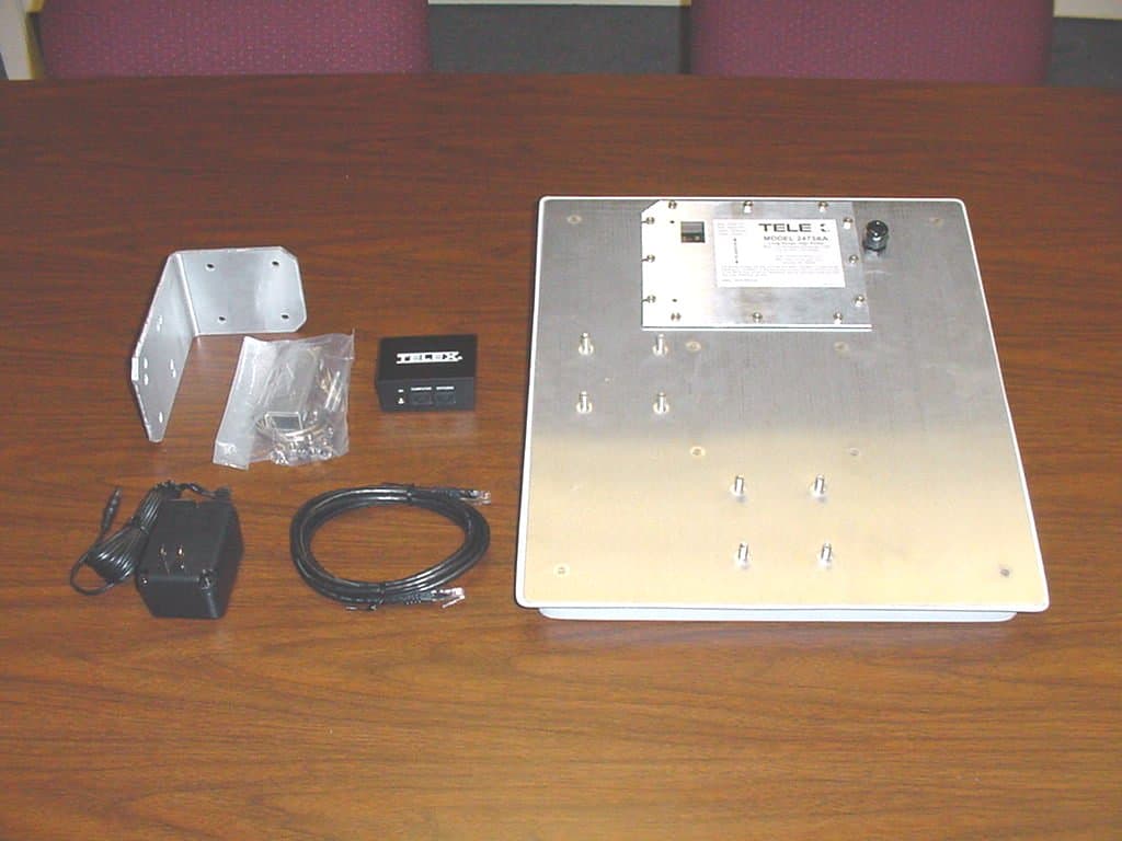
Click to zoom
Application Details
- Equipment Class
- DTS - Digital Transmission System
- Date of Grant
- Sep 11, 2003
- Application Purpose
- Original Equipment
- Date of Application
- Sep 11, 2003
- Equipment Note
- Wireless CPE/Outdoor Bridge
- Frequency Range
- 2412.00000000 - 2462.00000000
- Company
- Bosch Security Systems, Inc.
- Country
- United States
Documents & Files
Document Text
Text extracted from the exhibit documents filed with the FCC. Open a document above to read the original.
Users Manual
Model 2473AA Long Range, High Power Wireless CPE/Outdoor Bridge Instruction Manual Telex Communications, Inc. 8601 East Cornhusker Hwy, Lincoln, NE 68505 Revision D, September 2003 2 COPYRIGHT & TRADEMARKS Copyright @ 2003 Telex Communications, Inc., All Rights Reserved. Microsoft, Windows, and the Windows logo are registered trademarks of Microsoft Corporation. All other trademarks and brand names are the property of their respective proprietors. LIMITED WARRANTY TELEX Communications, Inc. ("Telex") warrants to the user who originally purchased the product, that the product will be free from defects in material and workmanship for the following periods after such date of purchase: Material 12 months, workmanship 12 months. Telex will at its option repair or replace free of charge such defective products subject to the following conditions: 1. Delivery of the product or parts prepaid directly to Telex Communications, Inc. at the following address: Service Department Telex Communications, Inc. 8601 East Cornhusker Highway Lincoln, NE 68505 2. Determination by Telex that a defect exists and is covered by the limited warranty. Defects due to alterations, repair by an unauthorized person, insertion of non-Telex parts, misuse, accidental damage, use of the equipment for purposes other than those for which it was designed and the like, are not covered by this limited warranty and repairs thereof will be subject to normal service charges. 3. Repairs and replacement parts are covered under this limited warranty only for the unexpired term of the original limited warranty. 4. Equipment returned to the factory for warranty repair must be accompanied by a proof of date of purchase and a statement of the reported malfunction. 3 Questions regarding warranty service information or repair status should be addressed to: Service Department Telex Communications, Inc. 8601 East Cornhusker Highway Lincoln, NE 68505 Telephone: (402) 467-5321 VALID IN UNITED STATES AND CANADA ONLY THIS LIMITED WARRANTY IS EXPRESSLY IN LIEU OF ANY EXPRESS OR IMPLIED WARRANTY, INCLUDING ANY IMPLIED WARRANTY OR MERCHANTABILITY OR FITNESS FOR A PARTICULAR PURPOSE, WHICH EXTENDS BEYOND THE TERM HEREOF. THE REMEDIES PROVIDED BY THIS LIMITED WARRANTY ARE THE ONLY REMEDIES AVAILABLE TO ANY PERSON. NO PERSON HAS ANY AUTHORITY TO BIND TELEX TO ANY REPRESENTATION OR WARRANTY OTHER THAN THOSE PROVIDED BY THIS LIMITED WARRANTY. TELEX SHALL NOT BE LIABLE FOR ANY INCIDENTAL OR CONSEQUENTIAL DAMAGES CAUSED BY FAILURE OR OTHERWISE OF THE PRODUCT. Some states do not allow exclusions or limitations of incidental or consequential damages or limitations on how long an implied warranty lasts, so the limitations or exclusions herein may not apply to you. This warranty gives you specific legal rights, and you may also have other rights, which vary from state to state. FCC STATEMENT This Wireless CPE has been tested and complies with the specifications for a Class B digital device, pursuant to Part 15 of the FCC Rules. These limits are designed to provide reasonable protection against harmful interference in a residential installation. This equipment generates, uses, and can radiate radio frequency energy and, if not installed and used according to the instructions, may cause harmful interference to radio communications. However, there is no guarantee that interference will not occur in a particular installation. If this equipment does cause harmful interference to radio or television reception, which is found by turning the equipment off and on, the user is encouraged to try to correct the interference by one or more of the following measures: • Reorient or relocate the receiving antenna • Increase the separation between the equipment or devices • Connect the equipment to an outlet other than the receiver’s • Consult a dealer or an experienced radio/TV technician for assistance 4 Changes or modifications not expressly approved by the manufacturer could void the user’s authority to operate the equipment! FCC Radiation Exposure Statement This equipment complies with FCC radiation exposure limits set forth for an uncontrolled environment. This equipment should be installed and operated with minimum distance 40cm (15.75 inches) between the radiator and your body. Installation Requirements The antenna used for this transmitter must not be co-located or operating in conjunction with any other antenna or transmitter. The operator of this transmitter, or if the equipment is professionally installed, the installer, is responsible for ensuring that the system is used exclusively for fixed, point-to- point operations. 5 Table of Contents Warranty & Copyright Information 2 FCC Statement 3 Chapter 1: Introduction 6 The Telex Wireless CPE/Outdoor Bridge 6 Features 7 Package Contents 8 Chapter 2: Getting to Know the Wireless CPE 9 Inside the Wireless CPE 9 The Power-Over-Ethernet Injector 10 The Rear Panel LED’s 11 Chapter 3: Installing the Wireless CPE 12 Selecting a Mounting Location 12 Attaching the Mounting Bracket and Aiming 13 Routing the CAT5 cable 14 Connecting the Wireless CPE 14 Chapter 4: Configuring the Wireless CPE 16 Change your computer network settings 17 Change the CPE wireless settings 17 System Status 18 Configuration 20 Administration 22 Tools 23 Help 24 Reset your computer network settings 25 Chapter 5: Managing the Wireless CPE 26 Chapter 6: Troubleshooting 27 Chapter 7: Firmware Documentation 28 Chapter 8: Specifications 30 6 Chapter 1: Introduction The Telex Wireless CPE/Outdoor Bridge Perfect for the home or small office connection to the network, the Telex Wireless CPE (Customer Premise Equipment) extends wireless connectivity from an access point to any Ethernet-ready network device, such as a switch, router, desktop or notebook PC. The Wireless CPE simply and efficiently transmits data between 10Base-T and your wireless LAN or wireless ISP access point. The Telex Wireless CPE gives you the freedom to place any standard networked compute…
Text truncated - open the document above for the full version.
Cover Letter(s)
Page 1 of 1 NCEE NEBRASKA CENTER FOR EXCELLENCE IN ELECTRONICS 4740 Discovery Drive Lincoln, NE 68521 402-472-5880 8 September 2003 RE: Telex Communications FCC ID: B5D-CPE200MW Mr. Johnson: This letter is to inform you of the changes and additional measurements made in regards to the Telex Communications product FCC ID: B5D-CPE200MW. The only change to the configuration of the EUT while testing was the adjustment of the test firmware to power setting “F0”, this is the most correct setting for the radio card (FCC ID: NI3- 2511CD-PLUS3) found in this unit. In the final production unit the power level is not user configurable. The measurements presented in NCEE report “R052203-01A” were made using that power setting; both conducted and radiated measurements from the RF port are presented. The conducted emissions results were unaffected. Doug Kramer Lab Manager NCEE
Cover Letter(s)
American Telecommunications Certification Body Inc. 6731 Whittier Ave, McLean, VA 22101 July 8, 2003 RE: Telex Communications, Inc. FCC ID: B5DCPE200MW (???) After a review of the submitted information, I have a few comments on the above referenced Application. 1) Please comment on the antenna. Is this antenna considered to be phased-array or steered-beam antenna? If so, please provide further detailed information regarding the antenna, gain, etc. Please note that if the device does contain either of these, we have been requested to consult the FCC before issuing the grant and may require more detailed information. 2) The 731 form shows the FCC ID as B5DCPE200MW, while the labeling shows B5D-CPE200MW. Please confirm the correct FCC ID and correct all affected exhibits. 3) Please provide an RF exposure exhibit for this device. 4) Please provide a Users Manual Exhibit. This must include all appropriate FCC statements and RF exposure information. 5) Please provide test photographs for the radiated tests as a separate exhibit. 6) Section 4.3 of the test report states testing to 15.209 but that the TX was not active. Please note that 15.209 is applied only during TX mode of operation, while 15.109 is applied during RX or idle conditions. Please correct the test report as necessary. 7) AC conducted emissions must be shown for both Phase and Neutral conductors. Please provide the missing information. 8) It is uncertain what the plots found on pages 10-12 of the test report are showing compliance to. Please explain. 9) Please confirm that this device will only be sold with the PCMCIA Card specified in this application. 10) The device does not appear to have been tested at the lowest and highest available channels (2412 & 2462 MHz) as given on the 731 form and required by 15.31. If these channels are not to be used in the end device, please provide information regarding the lowest and highest TX channels. Additionally, please note that the end user must not be capable of setting channels not approved within this application. Please explain how this is accomplished in the final device (reference 15.15(b)). 11) Please provide information regarding the RBW and VBW settings used for all radiated measurements. 12) Several of the limits do not appear to be correctly applied. For instance, measurements made in the 4.5 GHz to 5.15 GHz range should have a limit of 54 dBuV/m for AVG and 74 dBuV/m for Peak since they fall in a restricted band of operation. This range on page 13 & 14 does not appear to be correctly shown and it appears to exceed the limits for several measurements. 13) Please provide detailed information (including plots) to show compliance in the restricted bands at the band edges (2310-2390 and 2483.5-2500 MHz) to the 54 and 75 dBuV/m limits. 14) Even thought this device uses a previously approved TX, all applications must be complete and stand on their own. Please note that compliance of the power, 6 dB bandwidth, power spectral density, etc. has not been provide. Please provide this additional test data. Please see that additional attachment which explains appropriate test methods. Timothy R. Johnson Examining Engineer Direct Phone: 404-414-8071 mailto: [email protected] The items indicated above must be submitted before processing can continue on the above referenced application. Failure to provide the requested information may result in application termination. Correspondence should be considered part of the permanent submission and may be viewed from the Internet after a Grant of Equipment Authorization is issued. z Page 2July 8, 2003 Please do not respond to this correspondence using the email reply button. In order for your response to be processed expeditiously, you must submit your documents through the AmericanTCB.com website. Also, please note that partial responses increase processing time and should not be submitted. Any questions about the content of this correspondence should be directed to the sender.
Cover Letter(s)
Page 1 of 3 NCEE NEBRASKA CENTER FOR EXCELLENCE IN ELECTRONICS 4740 Discovery Drive Lincoln, NE 68521 402-472-5880 28 July 2003 FCC ID: B5D-CPE200MW Mr. Johnson: Please see the response to your comments below: 1) Please comment on the antenna. Is this antenna considered to be phased-array or steered- beam antenna? If so, please provide further detailed information regarding the antenna, gain, etc. Please note that if the device does contain either of these, we have been requested to consult the FCC before issuing the grant and may require more detailed information. The antenna is a fixed-beam patch array. It is not electrically steerable. 2) The 731 form shows the FCC ID as B5DCPE200MW, while the labeling shows B5D- CPE200MW. Please confirm he correct FCC ID and correct all affected exhibits. B5D-CPE200MW is the correct FCC ID. A new 731 form will be submitted if required, the report has been modified. 3) Please provide an RF exposure exhibit for this device. The document has been submitted for review. 4) Please provide a Users Manual Exhibit. This must include all appropriate FCC statements and RF exposure information. The document has been submitted for review. 5) Please provide test photographs for the radiated tests as a separate exhibit. The document has been submitted for review. 6) Section 4.3 of the test report states testing to 15.209 but that the TX was not active. Please note that 15.209 is applied only during TX mode of operation, while 15.109 is applied during RX or idle conditions. Please correct the test report as necessary. The report has been modified to clarify the measurements. Page 2 of 3 7) AC conducted emissions must be shown for both Phase and Neutral conductors. Please provide the missing information. The results as shown represent a worst-case from both the Phase and Neutral conductors; the report has been modified to clarify that. 8) It is uncertain what the plots found on pages 10-12 of the test report are showing compliance to. Please explain. The report has been modified to remove the ambiguity. 9) Please confirm that this device will only be sold with the PCMCIA Card specified in this application. Yes, this is correct. This device will only be sold with the PCMCIA card specified in the application. The FCC ID of the card is NI3-2511CD-PLUS3. 10) The device does not appear to have been tested at the lowest and highest available channels (2412 & 2462 MHz) as given on the 731 form and required by 15.31. If these channels are not to be used in the end device, please provide information regarding the lowest and highest TX channels. Additionally, please note that the end user must not be capable of setting channels not approved within this application. Please explain how this is accomplished in the final device (reference 15.15(b)). The device firmware allows operation only on channels 1 through 11. Measurements were made according to 15.31 requiring measurements near top, near middle and near bottom of the band of operation. Measurements of the lower and upper frequencies have been added to show overall compliance to the operational range of 2400-2483.5 MHz. 11) Please provide information regarding the RBW and VBW settings used for all radiated measurements. All radiated measurements above 1GHz were made 1MHz RBW and measurements below 1GHz were made with 120kHz RBW as stated in Section 4.0 of the report unless otherwise noted. 12) Several of the limits do not appear to be correctly applied. For instance, measurements made in the 4.5 GHz to 5.15 GHz range should have a limit of 54 dBuV/m for AVG and 74 dBuV/m for Peak since they fall in a restricted band of operation. This range on page 13 & 14 does not appear to be correctly shown and it appears to exceed the limits for several measurements. The results have been remeasured, recalculated and represented in the report. A high pass filter was used during measurements above 2GHz and a low pass filter used in measurements below 1GHz. A 10dB attenuator was used when measuring the fundamental. The report has been modified to correctly reflect this and all values have been verified. 13) Please provide detailed information (including plots) to show compliance in the restricted bands at the band edges (2310-2390 and 2483.5-2500 MHz) to the 54 and 75 dBuV/m limits. Plots have been added to the report that show the equipment does not pass into those bands when operating at its extreme frequencies. Page 3 of 3 14) Even thought this device uses a previously approved TX, all applications must be complete and stand on their own. Please note that compliance of the power, 6 dB bandwidth, power spectral density, etc. has not been provide. Please provide this additional test data. Please see that additional attachment which explains appropriate test methods. Thank you for this information. The changes made to the report should provide adequate detail. Sincerely, Doug Kramer Lab Manager NCEE
Operational Description
FCC ID: B5D-CPE200MW Operational Description The DSSS transmitter and receiver of the EUT (Long range, high power wireless CPE) is powered via a PCMCIA interface to the LAN interface PCB. The transmitter and receiver of the EUT are connected to an 18 dBi patch antenna array within the CPE radome enclosure. The LAN interface PCB is connected to an outdoor-rated Ethernet cable (CAT-5) from which it receives both data and DC power. The DC power is injected onto wires 4,5,7 and 8 from a Power-over-Ethernet (PoE) box, which is located near the client’s computer equipment. The client’s computer equipment is also connected to the PoE box with a short length of CAT-5 Ethernet cable. The DSSS transmitter and receiver consists of a PCMCIA radio card, Senao model NL- 2511CD PLUS EXT2 (FCC ID: NI3-2511CD-PLUS3).
RF Exposure Info
FCC ID: B5D-CPE200MW RF Exposure Statement for Telex Model 2473AA: Notice in Installation Manual: FCC Radiation Exposure Statement This equipment complies with FCC radiation exposure limits set forth for an uncontrolled environment. This equipment should be installed and operated with minimum distance 40cm (15.75 inches) between the radiator and your body. RF Exposure Calculations: The following information provides the minimum separation distance for the 18 dBi antenna provided as an integral part of Telex Model 2473AA CPE product, as calculated from FCC OET 65 Appendix B, Table 1B Guidelines for General Population/Uncontrolled Exposure. This calculation is based on the highest EIRP possible from the system, considering maximum power and antenna gain, and considering a 1.0 mW/cm^2 uncontrolled exposure limit. The formula used was: S = (Po * G) / (4 * Pi * r^2) or r = SQRT [ (Po * G) / (4 * Pi * S) ] Where S = 1.0 mW/cm^2 for 2400 MHz Where Po = 200 mW (Peak RF) Where G = 63.1 (numeric equivalent to 18 dBi antenna gain) Where r = Minimum Safe Distance from antenna (cm) For Telex Model 2473AA, r = 32 cm (12.77 inches) Notes: 1. The minimum safe distance is based on a conservative “worse case” prediction, i.e. using the formula shown above and no duty factor. In practice the minimum distance could be much shorter. (Ref. 2) 2. The minimum safe distance has been calculated for the maximum allowed Power Density (S) limit of 1.0 mW/cm^2 in the frequency range 1500-100,000 MHz for uncontrolled environments (Ref. 2). 3. The users manual and all documentation for this product recommend a minimum distance of 40cm even though the calculated value is 32cm. References: 1. FCC Part 15, sub-clause 15.247 (b) (4) (i) 2. FCC OET Bulletin 65, Edition 97-01 3. FCC Supplement C to OET Bulletin 65, edition 01-01
Test Report
R052203-01A FCC ID: B5D-CPE200MW NCEE NEBRASKA CENTER FOR EXCELLENCE IN ELECTRONICS 4740 Discovery Drive Lincoln, NE 68521 402-472-5880 Test Report Company: Telex Communications 8601 East Cornhusker Highway Lincoln, NE 68505 Contact: Roger Cox Product: 2473AA FCC ID: B5D-CPE200MW Test Report No: R052203-01A APPROVED BY: Steve Cass _________________________ General Manager Doug Kramer _________________________ Test Engineer DATE: 15 September 2003 Total Pages: 56 The Nebraska Center for Excellence in Electronics (NCEE) authorizes the above named company to reproduce this report provided it is reproduced in its entirety for use by the company’s employees only. Any use that a third party makes of this report, or any reliance on or decisions made based on it, are the responsibility of such third parties. NCEE accepts no responsibility for damages, if any, suffered by any third party as a result of decisions made or actions based on this report. This report applies only to the items tested. NCEE is a FCC registered lab. Registration #100875 NCEE R052203-01A FCC ID: B5D-CPE200MW Page 2 of 56 Table of Contents 1.0 Summary of test results 1.1 Test Results 1.2 Test Methods 1.2.1 Conducted Emissions 1.2.2 Radiated Emissions 1.3 Reason for amendment 2.0 Description 2.1 Equipment under test 2.1.1 Identification 2.1.2 EUT received date 2.1.3 EUT tested dates 2.1.4 Manufacturer 2.1.5 Serial number 2.2 Laboratory description 2.3 Special equipment or setup 3.0 Test equipment used 4.0 Detailed Results 4.1 FCC Part 15.203 unique connector for antenna 4.2 FCC Part 15.207 Conducted Emissions 4.3 FCC Part 15.109 Radiated Emissions, Rx only 4.4 FCC Parts 15.209 and 15.247 Radiated Emissions, Tx only Appendix A – Test setup photos Appendix B – Emissions results Appendix C – Sample calculation Appendix D – Bandedge Measurements and Data NCEE R052203-01A FCC ID: B5D-CPE200MW Page 3 of 56 1.0 Summary of test results 1.1 Test Results 1.2 Test Methods 1.2.1 Conducted Emissions Measurements of conducted emissions to the limits set in CFR 47 Part 15.207 were conducted using the methods shown in ANSI/IEEE C63.4, 2001. Several configurations were examined the results presented represent a worst-case scenario. The EUT was placed on a wooden table approximately 80cm high, positioned 40cm from the vertical ground plane and 80cm or more away from any other conductive surface. 1.2.2 Radiated Emissions Compliance to CFR 47 Parts 15.109/209 and 15.247 was tested in accordance with the methods of ANSI/IEEE C63.4, 2001. Several configurations were examined the results presented represent a worst-case scenario. The EUT was placed on a wooden table approximately 80cm high and centered on a 4m diameter turntable. The table was rotated to maximize emissions. All measurements at 18GHz and below were taken at a distance of 3m from the EUT. Measurements between 18GHz and 25GHz were taken at a distance of approximately 1m from the EUT. 1.3 Reason for amendment This report has been modified to include additional data regarding the bandedges and power measurements. Test Test SpecificationResults CFR 47, FCC Part 15.203Part 15.203Complies CFR 47, FCC Part 15.207Part 15.207, Class BComplies CFR 47, FCC Part 15.209Part 15.109, Class BComplies CFR 47, FCC Part 15.247Parts 15.209 and 15.247 Complies NCEE R052203-01A FCC ID: B5D-CPE200MW Page 4 of 56 2.0 Description 2.1 Equipment under test The 2473AA access point integrates a 18dBi nominal gain patch antenna and interface for a PCMCIA 802.11b radio card (FCC ID: NI3-2511CD-PLUS3). The unit is powered by a 120VAC to 12VDC converter (GlobTek P/N WD2E1000LCP-N) connected through a power over ethernet box. 2.1.1 Identification: Telex 2473AA 2.1.2 EUT received date: 22 May 2003 2.1.3 EUT tested dates: 31 July, 22 August, 8 and 14 September 2003 2.1.4 Manufacturer: Telex Communications 2.1.5 Serial number: Proto1 2.2 Laboratory description All testing was performed at the NCEE Lincoln facility, which is a FCC registered lab. This site has been fully described in a report submitted to your office, and accepted in a letter dated May 4, 2001. Laboratory environmental conditions varied slightly throughout the tests: Relative humidity of 46 ± 4% Temperature of 21 ± 3° Celsius 2.3 Special equipment or setup The device was enabled to allow for continuous transmission at a single frequency. The network port of the EUT was “pinged” continuously. A high pass filter was used during radiated measurements between 3GHz and 18GHz and a low pass filter used in radiated measurements below 1GHz. When noted a 10dB attenuator was used when measuring the fundamental. The test firmware was configured at power level “F0” for testing. Cable routing must be as seen in Figure 4. 3.0 Test equipment used Serial # Manufacturer Model Description Last cal. 1654 EMCO 3142B Biconilog antenna 03-May-03 6415 EMCO 3115 DRG Horn 17-Sep-02 2576 EMCO 3116 DRG Horn 29-Apr-03 100037 Rohde & Schwarz ESIB26 EMI Test Receiver 02-Jul-03 100007 Rohde & Schwarz ESIB7 EMI Test Receiver 26-May-03 082001/003 Rohde & Schwarz TS-PR18 Preamplifier N/A 2575 Rohde & Schwarz ES-K1 Software v1.60 N/A 100023 Rohde & Schwarz ESH3-Z5 Artificial Mains 20-Sep-02 200332488 Trilithic 7900096000 High pass filter 31-Jul-03 15542 Mini-Circuits SLP-1200 Low pass filter 15-May-03 0119 Mini-Circuits BW-S10W2 10dB attenuator 15-May-03 3911A06945 HP 8594E Spectrum Analyzer 13-Sep-02 * *Telex equipment, calibration extended NCEE R052203-01A FCC ID: B5D-CPE200MW Page 5 of 56 4.0 Detailed Results All measurement results are located in the corresponding interval with a probability of approximately 95% (coverage factor k=2). The interval for these measurements is U x (expanded uncertainty). Conducted Emissions, 150kHz – 30MHz: U x = +/- 3.1 dB Radiated Emissions, 30MHz – 1GHz, 3m distance: U x = +/- 3.4 dB Radiated Emissions, 1GHz – 18GHz, 3m distance: U x = +/- 3.5 dB Radiated emissions measurements were made by first using a spectrum analyzer getting a rough signal spectr…
Text truncated - open the document above for the full version.
Contact Information
Applicant
James R Andersen(Principal Electrical Engineer)
Technical Contact
Telex Communications, IncRoger Cox
[email protected]402-465-7084
8601 East Cornhusker Highway · Lincoln, Nebraska · United States
Non-Technical Contact
Telex Communications, Inc.Jason Lardy
[email protected]952-884-4051
Test Firm
Nebraska Center for Excellence in ElectronicsSteve Cass
Technical Specifications
| # | Rule Parts | Frequency Range | Power Output |
|---|---|---|---|
| 1 | 15C | 2.41 GHz - 2.46 GHz | 159.00 mW |
Other Applications from Bosch Security Systems, Inc.

B5DM540
Jun 02, 2020Wireless microphone base station
Equipment Class
TLD - Licensed LPAS Device
B5DM542
Jun 01, 2020Wireless beltpack
Equipment Class
TLD - Licensed LPAS Device
B5DM541
May 27, 2020Wireless beltpack
Equipment Class
TLD - Licensed LPAS Device
B5DM536
Mar 18, 2020Single Receiver UHF Wireless Intercom Beltpack
Equipment Class
TLD - Licensed LPAS Device
B5DM539
Mar 18, 2020Dual Receiver Narrowband UHF Wireless Intercom Beltpack
Equipment Class
TLD - Licensed LPAS Device