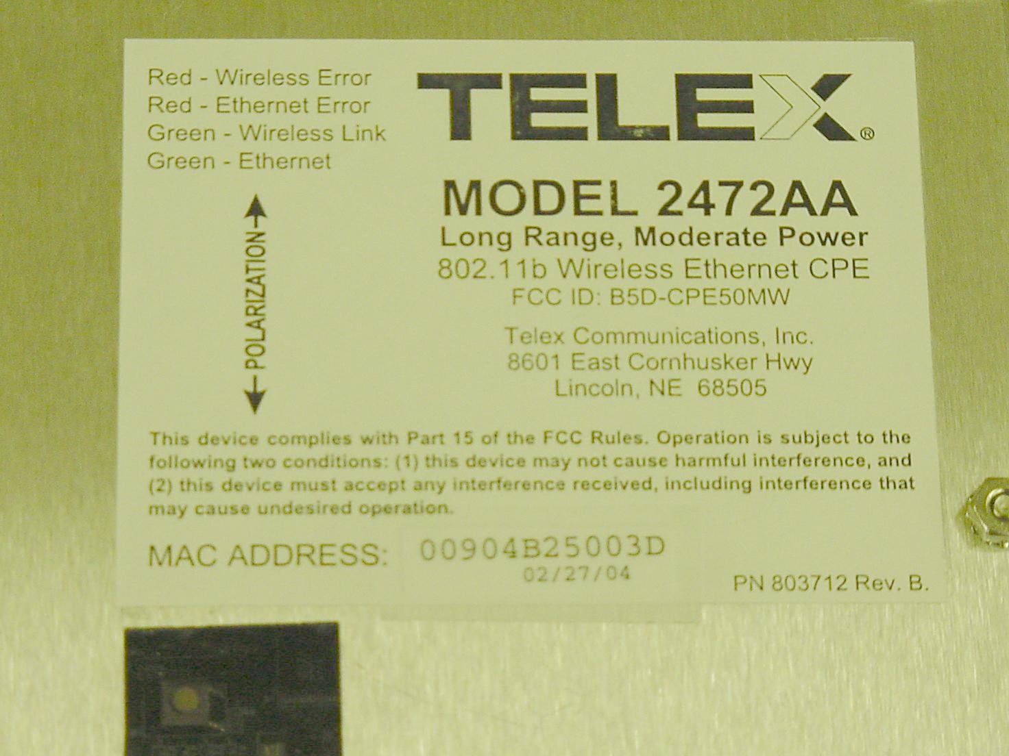
B5D-CPE50MW2472AA Wireless CPE/Outdoor Bridge
Bosch Security Systems, Inc.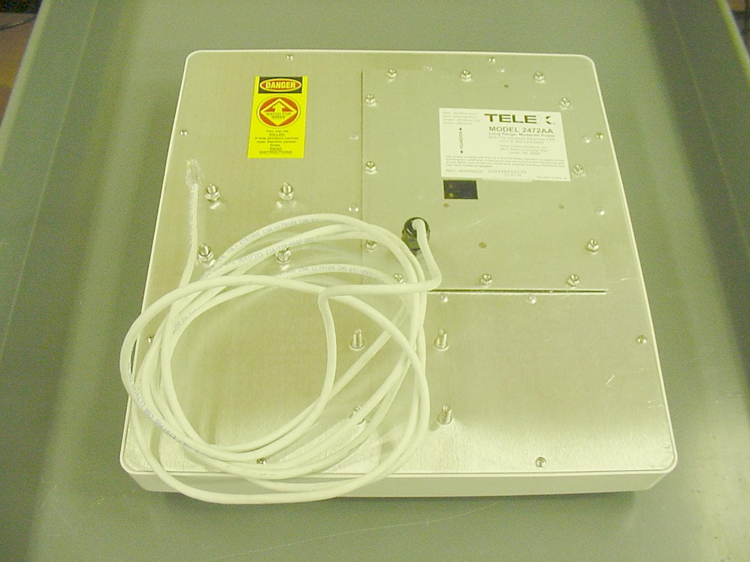
Click to zoom
Application Details
- Equipment Class
- DTS - Digital Transmission System
- Date of Grant
- Apr 21, 2004
- Application Purpose
- Original Equipment
- Date of Application
- Apr 21, 2004
- Equipment Note
- 2472AA Wireless CPE/Outdoor Bridge
- Frequency Range
- 2412.00000000 - 2462.00000000
- Company
- Bosch Security Systems, Inc.
- Country
- United States
Documents & Files
Document Text
Text extracted from the exhibit documents filed with the FCC. Open a document above to read the original.
Users Manual
Model 2472AA Long Range, Moderate Power Wireless CPE/Outdoor Bridge Instruction Manual Telex Communications, Inc. 8601 East Cornhusker Hwy, Lincoln, NE 68505 Rev. A, April 2004 2 COPYRIGHT & TRADEMARKS Copyright @ 2003 Telex Communications, Inc., All Rights Reserved. Microsoft, Windows, and the Windows logo are registered trademarks of Microsoft Corporation. All other trademarks and brand names are the property of their respective proprietors. TELEX LIMITED WARRANTY Uniform Limited Warranty: Telex branded products are warranted by Telex Communications, Inc. against malfunction due to defects in materials and workmanship for a specified period, as noted in the individual product-line statements below, beginning with the date of original purchase by the end- user. If such malfunction occurs during the specified period, the product will be repaired with new or remanufactured equivalent parts and products or replaced (at our option) without charge. The product will be returned to the customer prepaid. Exclusions and Limitations: The Limited Warranty does not apply to: (a) exterior finish or appearance; (b) certain specific items described in the individual product-line statements below, (c) malfunction resulting from use or operation of the product other than as specified in the product data sheet or owner’s manual; (d) malfunction resulting from misuse or abuse of the product, including accidents; (e) defects resulting from excess moisture, lightning or power surges; or (f) malfunction occurring at any time after repairs have been made to the product by anyone other than a Telex Service Department or any of its authorized service representatives. The Warranty is void if the label bearing the product serial number (if applicable) has been removed or defaced. Other Express or Implied Warranties Excluded: TO THE EXTENT PERMITTED BY APPLICABLE LAW, THE WARRANTIES SET FORTH HEREIN ARE IN LIEU OF, AND EXCLUSIVE OF, ALL OTHER WARRANTIES, EXPRESS OR IMPLIED. SPECIFICALLY EXCLUDED, WITHOUT LIMITATION, ARE THE WARRANTIES OF MERCHANTABILITY, FITNESS FOR USE OR FOR A PARTICULAR PURPOSE, AND WARRANTIES ARISING FROM COURSE OF DEALING OR USAGE OF TRADE OR ANY OTHER MATTER. IF, UNDER APPLICABLE LAW, IMPLIED WARRANTIES MAY NOT BE VALIDLY EXCLUDED, THE DURATION OF SUCH IMPLIED WARRANTIES IS LIMITED TO THE WARRANTY PERIOD. Limitation of Remedies; Certain Damages Excluded: REPAIR OR REPLACEMENT OF DEFECTIVE PRODUCTS ARE THE SOLE AND EXCLUSIVE REMEDIES PROVIDED BY TELEX TO THE CUSTOMER OR TO ANY OTHER PERSON AND SHALL CONSTITUTE FULL SATISFACTION OF ALL CLAIMS, WHETHER BASED ON CONTRACT, NEGLIGENCE, STRICT LIABILITY OR OTHERWISE. TELEX’s MAXIMUM LIABILITY SHALL NOT EXCEED THE ACTUAL PURCHASE PRICE PAID FOR THE PRODUCT BY THE CUSTOMER. TELEX AND ITS SUBSIDIARIES SHALL NOT BE LIABLE FOR ANY INDIRECT, INCIDENTAL, PUNITIVE, SPECIAL OR CONSEQUENTIAL DAMAGES INCLUDING, WITHOUT LIMITATION, INJURY TO PERSONS OR PROPERTY OR LOSS OF USE. SOME STATES AND COUNTRIES DO NOT ALLOW THE EXCLUSION OR LIMITATION OF CERTAIN DAMAGES, SO THE ABOVE LIMITATION OR EXCLUSION MAY NOT APPLY TO YOU. IN SUCH STATES AND COUNTRIES, TELEX SHALL BE LIABLE FOR NO MORE THAN THE DIRECT DAMAGES FOR BODILY INJURY AND/OR REAL OR PERSONAL PROPERTY ARISING FROM THE NEGLIGENCE OF TELEX. Other Rights: This warranty gives you specific legal rights, and you may also have other rights, depending upon where you live. Obtaining Warranty Service: To obtain warranty service, a customer must deliver the product, prepaid, to the appropriate Telex Service Department listed below or any of its authorized service representatives together with proof of purchase of the product in the form of a bill of sale or invoice. Applicable Law. The validity, performance and construction of this Limited Warranty shall be governed by the laws of the State of Minnesota without reference to its choice of law principles. The Minnesota federal courts and/or the state courts located in Hennepin County, Minnesota, shall have exclusive personal and subject matter jurisdiction over, and the parties shall each submit to the jurisdiction of such courts and to venue in Minnesota with respect to any dispute concerning the product or pursuant to this Limited Warranty, and all objections to such jurisdiction or to such venue are hereby waived. For additional warranty repair or service information, contact the appropriate Telex service department listed below: USA, Canada & Latin America (DUPLICATION) (WIRELESS, VEGA, WALS, LANDMOBILE) Telex Communications, Inc. 8601 E Cornhusker Way West First Street Lincoln, NE 68507 Blue Earth, MN 56013 USA Tel: 402-467-5321 Tel: 507/526-3205 Fax: 402-467-3279 Fax: 507/526-3059 (EDUCATION AND AVIATION HEADSETS) 1720 E 14 th Street Glencoe, MN 55336 Tel: 320-864-3177 Fax: 320-864-3225 Germany, Rest of Europe and Africa & Middle East Mexico (Duplication) (CB MICS) Telex EVI Audio GmbH. Saguaro Elect Hirschberger Ring 45 Hermosillo, Mexico 83280 D 94315, Straubing, Germany Tel: 011 5262 607012 Phone: +49 9421-706 0 Fax: 011 5262 607010 Fax: +49 9421-706 265 3 FCC STATEMENT This Wireless CPE has been tested and complies with the specifications for a Class B digital device, pursuant to Part 15 of the FCC Rules. These limits are designed to provide reasonable protection against harmful interference in a residential installation. This equipment generates, uses, and can radiate radio frequency energy and, if not installed and used according to the instructions, may cause harmful interference to radio communications. However, there is no guarantee that interference will not occur in a particular installation. If this equipment does cause harmful interference to radio or television reception, which is found by turning the equipment off and on, the user is encouraged to try to correct the interference by one or more of the following measures: • Reorient or relocate the receiving antenna • Increase the separation between the equipment or devices • Connect the equipment t…
Text truncated - open the document above for the full version.
Block Diagram
ANT SW WE P EN G I N E 2. 4G H z BP F TX / R X SW MI XE R SA W FI LTER AGC CT L LN A TX / R X SW PL L 20 38- 20 98M H z AM P MI XE R AM P AM P AMP TX / R X SW MI XE R MI XE R AMP MI XE R MI XE R LO AM P PLL Q DA C T X DAC T X ADC Q AD C I ADC I DAC RF DAC RF ADC IF DAC DE M ODUL ATOR I/ O M ODUL A T OR TX AL C HOS T IN T E R F A C E CO N T RO L P R O C E SSO R ME M O RY AC CE S S A R BI TER GP S E R I A L PO R T S FL A S H ME MO R Y RA D I O C ONTR O L ] PO R T S RA D I O DAT A IN T E R F A C E SR A M ME M O RY CP U PC M C I A IN T E R F A C E 44M H z XT AL OS C 2. 4G H z VCO 748M H z VCO U1 1 RF / I F CONV U9 Q U A D I F C ONV U4 M AC/ B B P U3 C PU FL 1 U6 X TA L OS C 37 4 M H z s a w f i l t e r FL 4 BPF U1 0 AN T SW U1 4 RF V CO U1 3 I F V C O REG 3 . 3 V VS S REG3 . 3 V 3. 0V AMP BPF FL 5 U1 2 POW E R AM P U1 5 U7 U4 , U 1 ME M O R Y U2 ME M O R Y RXI RXQ TXI TX Q DA T A TX / R X 2412-2462 MHz REG 3 . 3 V VSS 3. 3V ~ 5 V MMCX connector WL-316C WLAN CARD BLOCKDIAGRAM
Cover Letter(s)
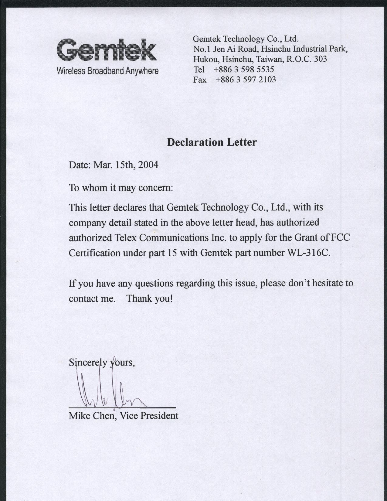
February 26, 2004 American Telecommunications Certification Body, Inc. 6731 Whittier Avenue Suite C110 McLean, VA 22101 RE: Certification Application FCC ID: B5D-CPE50MW Confidentiality Request Pursuant to Sections 0.457 and 0.459 of the Commission’s Rules, the Applicant hereby requests confidential treatment of information accompanying this Application as outlined below: For the SparkLan Wireless LAN card used within the device: Schematics Block Diagram The above materials contain trade secrets and proprietary information not customarily released to the public. The public disclosure of these matters might be harmful to the Applicant and provide unjustified benefits to its competitors. The Applicant understands that pursuant to Rule 0.457, disclosure of this Application and all accompanying documentation will not be made before the date of the Grant for this application. Sincerely, Paul Hoffmeyer Antenna Engineering Manager Telex Communications, Inc.
Cover Letter(s)
American Telecommunications Certification Body Inc. 6731 Whittier Ave, McLean, VA 22101 April 18, 2004 RE: FCC ID: B5D-CPE50MW_ATCB001275 Attention: Doug Kramer / Roger Cox I have a few comments on this Application. 1. Please note that as schematics are typically held confidential ATCB has no way of procuring them from the FCC. If ATCB certified the product, ATCB still cannot access the schematics unless the application number and the original applicant name is provided. Please provide the schematics for this product or alternately, please provide the necessary information along with a letter from the original applicant that states you have permission to use the schematic. 2. Please note that as block diagrams are typically held confidential ATCB has no way of procuring them from the FCC. If ATCB certified the product, ATCB still cannot access the block diagram unless the application number and the original applicant name is provided. Please provide the block diagram for this product or alternately, please provide the necessary information along with a letter from the original applicant that states you have permission to use the block diagram. 3. Please note that all applications must stand on their own merit. Please provide the internal photos for the PCMCIA card. Please provide photos of the PCMCIA card in successive stages of tear down. Please provide photos of both sides of the PCB and components of the PCMCIA card. 4. Please note that even though the separation distance calculations for this device is less than 20 cm, it is a mobile device requiring 20cm separation. As such the value of S should be calculated at 20cm not the distance where the 1mw/cm^2 occurs. Please show an MPE report giving the value of S at 20cm. Also, please note that the MPE report rf exposure distance statement and the actual statement in the manual do not agree. Please put a minimum separation statement of 20cm in the manual and in the MPE report.. 5. In relation to item 4 – Please note that as you have listed the separation distance in the manual as 15.8 cm you have automatically put this device in the portable rf exposure category. Since the power exceed the <20 max power formula in the TCB exclusions list you must either correct the manual to state at least 20 cm separation is required, or you must perform SAR on the device. Please note that it is the conducted and/or EIRP power that must be used in the formula. This means that the power of this device would be 50mW (19.99dB) plus 18dB or 34.99dBm (over 1 watt). This is significantly over the max 375mw allowed for less than 20cm operation. Please provide either a corrected manual with the corrected 20cm statement or please provide the SAR report for this device. 6. Please note that the report states that the antenna is integral to the PCMCIA card. However, the theory of operation states, “The transmitter and receiver of the EUT are connected to an 18 dBi patch antenna array within the CPE radome enclosure.” How is this done? Is there a physically connection between the PCMCIA antenna and the 18dBi antenna, or is there another connection mechanism. Please adequately explain how this is done and please correct the report to adequately express how this device is used in this application (not how the PCMCIA card was originally certified). 7. Please verify that the radiated spurious emissions test in the report was performed with the 18dBi antenna connected and not with just the internal PCMCIA antenna. 8. Please note that in the radiated emissions table for the transmitter you show readings for frequencies outside the restricted bands as over the limit. Please note that the readings outside the restricted bands only need to be 20dB below the fundamental. Please compare the readings to the correct limits. 9. Please note that the table on page 40 of the report is listed as being the “calculated restricted band values based on based on the measured values from the EUT.” What does this mean? It appears as if you have calculated compliance of the restricted bands. Please note that this not allowed. Restricted band compliance for part 15 devices is strictly a measured values as stated in 15.209a z Page 2 April 18, 2004 and 15.247c. It also appears as if you have made 3 meter radiated emissions measurements. Please explain the chart on page 40 of the report. 10. Please note that you do not appear to have provided a proper peak conducted or EIRP power for this device. Please note that it is stated to be a 50mw conducted power device. Page 6 of the report states that you derived power measurements from plots 29 through 37. Please note that none of the plots (29 through 37) show the proper resolution or video bandwidths for peak power measurements required by 15.247. Please note that for power measurements using an analyzer the res BW must be wider than the band width of the device or a bandwidth correction factor must be applied. The video BW must be greater than the Res BW. Alternately a peak power meter can be used. Please note that you do not appear to have used the correct resolution and video bandwidths nor does it appear that you have included a resolution bandwidth correction factor in the peak power measurements. The resolution bandwidth correction factor is 10log(EUT 6dBBW/res BW). In this case, 10log[11m/1m] or 10dB. Please re-measure the peak conducted power of this device using the proper resolution bandwidth (including any bandwidth correction factor as needed) and the proper video bandwidth (which would be greater than the resolution bandwidth). 11. Please provide a separate test setup photo exhibit. Dennis Ward mailto:[email protected] The items indicated above must be submitted before processing can continue on the above referenced application. Failure to provide the requested information may result in application termination. Correspondence should be considered part of the permanent submission and may be viewed from the Internet after a Grant of Eq…
Text truncated - open the document above for the full version.
Cover Letter(s)
From: Doug Kramer [mailto:[email protected]] Sent: Thursday, April 22, 2004 9:53 AM To: dward ATCB Subject: RE: B5D-CPE50MW_ATCB001275 Dennis, Yes, that is correct, is that information that should be included somewhere in the report and if so, do you have any suggestions? Doug -----Original Message----- From: dward ATCB [mailto:[email protected]] Sent: Thursday, April 22, 2004 11:46 AM To: 'Doug Kramer' Subject: RE: B5D-CPE50MW_ATCB001275 Hi Doug Your numbers don't add up in the tables for radiated emissions. They appear to be off a little. I am assuming that it is because they are from actual 2 decimal calculations while the table for the transducer and cables only have 1 decimal place. Is this correct??? Dennis
Cover Letter(s)
Page 1 of 3 21 April 2004 RE: Telex Communications FCC ID: B5D-CPE50MW Mr Ward: This letter is in response to your letter date 18 April 2004, below your comments you will find a response in italics. 1. Please note that as schematics are typically held confidential ATCB has no way of procuring them from the FCC. If ATCB certified the product, ATCB still cannot access the schematics unless the application number and the original applicant name is provided. Please provide the schematics for this product or alternately, please provide the necessary information along with a letter from the original applicant that states you have permission to use the schematic. The schematics have been uploaded. 2. Please note that as block diagrams are typically held confidential ATCB has no way of procuring them from the FCC. If ATCB certified the product, ATCB still cannot access the block diagram unless the application number and the original applicant name is provided. Please provide the block diagram for this product or alternately, please provide the necessary information along with a letter from the original applicant that states you have permission to use the block diagram. A block diagram was uploaded on 21 April 2004. 3. Please note that all applications must stand on their own merit. Please provide the internal photos for the PCMCIA card. Please provide photos of the PCMCIA card in successive stages of tear down. Please provide photos of both sides of the PCB and components of the PCMCIA card. Photos of the PCMCIA card have been uploaded for review. 4. Please note that even though the separation distance calculations for this device is less than 20 cm, it is a mobile device requiring 20cm separation. As such the value of S should be calculated at 20cm not the distance where the 1mw/cm^2 occurs. Please show an MPE report giving the value of S at 20cm. Also, please note that the MPE report rf exposure distance statement and the actual statement in the manual do not agree. Please put a minimum separation statement of 20cm in the manual and in the MPE report. 5. In relation to item 4 – Please note that as you have listed the separation distance in the manual as 15.8 cm you have automatically put this device in the portable rf exposure category. Since the power exceed the <20 max power formula in the TCB exclusions list you must either correct the NCEE NEBRASKA CENTER FOR EXCELLENCE IN ELECTRONICS 4740 Discovery Drive Lincoln, NE 68521 402-472-5880 Page 2 of 3 manual to state at least 20 cm separation is required, or you must perform SAR on the device. Please note that it is the conducted and/or EIRP power that must be used in the formula. This means that the power of this device would be 50mW (19.99dB) plus 18dB or 34.99dBm (over 1 watt). This is significantly over the max 375mw allowed for less than 20cm operation. Please provide either a corrected manual with the corrected 20cm statement or please provide the SAR report for this device. A revised manual has been uploaded to address items 4 and 5. 6. Please note that the report states that the antenna is integral to the PCMCIA card. However, the theory of operation states, “The transmitter and receiver of the EUT are connected to an 18 dBi patch antenna array within the CPE radome enclosure.” How is this done? Is there a physically connection between the PCMCIA antenna and the 18dBi antenna, or is there another connection mechanism. Please adequately explain how this is done and please correct the report to adequately express how this device is used in this application (not how the PCMCIA card was originally certified). The particular PCMCIA card in question does not have an internal antenna. The original grant for FCC ID: MXF-C900924 shows the unit as being tested with low gain external omni directional antenna. The report has been clarified to state, “this PCMCIA card and coaxial cable are internal to the 2472AA (FCC ID: B5D-CPE50MW).” 7. Please verify that the radiated spurious emissions test in the report was performed with the 18dBi antenna connected and not with just the internal PCMCIA antenna. All radiated emissions tests were performed with the 18dBi antenna as shown in the test setup photos. 8. Please note that in the radiated emissions table for the transmitter you show readings for frequencies outside the restricted bands as over the limit. Please note that the readings outside the restricted bands only need to be 20dB below the fundamental. Please compare the readings to the correct limits. The tables in the report have been adjusted to show the limit as 20dB below the fundamental. 9. Please note that the table on page 40 of the report is listed as being the “calculated restricted band values based on based on the measured values from the EUT.” What does this mean? It appears as if you have calculated compliance of the restricted bands. Please note that this not allowed. Restricted band compliance for part 15 devices is strictly a measured values as stated in 15.209a and 15.247c. It also appears as if you have made 3 meter radiated emissions measurements. Please explain the chart on page 40 of the report. The restricted band values are based on the radiated measured values for a given antenna and in comparison with the measured conducted values. The report has been amended to clarify this. 10. Please note that you do not appear to have provided a proper peak conducted or EIRP power for this device. Please note that it is stated to be a 50mw conducted power device. Page 6 of the report states that you derived power measurements from plots 29 through 37. Please note that none of the plots (29 through 37) show the proper resolution or video bandwidths for peak power measurements required by 15.247. Please note that for power measurements using an analyzer the res BW must be wider than the band width of the device or a bandwidth correction factor must Page 3 of 3 be applied. The video BW must be greater than the Res BW. Alternately a peak po…
Text truncated - open the document above for the full version.
RF Exposure Info
FCC ID: B5D-CPE50MW RF Exposure Statement for Telex Model 2472AA: Notice in Installation Manual: FCC Radiation Exposure Statement This equipment complies with FCC radiation exposure limits set forth for an uncontrolled environment. This equipment should be installed and operated with minimum distance 40cm (15.75 inches) between the radiator and your body. RF Exposure Calculations: The following information provides the minimum separation distance for the 18 dBi antenna provided as an integral part of Telex Model 2472AA CPE product, as calculated from FCC OET 65 Appendix B, Table 1B Guidelines for General Population/Uncontrolled Exposure. This calculation is based on the highest EIRP possible from the system, considering maximum power and antenna gain, and considering a 1.0 mW/cm^2 uncontrolled exposure limit. The formula used was: S = (Po * G) / (4 * Pi * r^2) or r = SQRT [ (Po * G) / (4 * Pi * S) ] Where S = 1.0 mW/cm^2 for 2400 MHz Where Po = 50 mW (Peak RF) Where G = 63.1 (numeric equivalent to 18 dBi antenna gain) Where r = Minimum Safe Distance from antenna (cm) For Telex Model 2472AA, r = 15.8 cm (6.24 inches) Notes: 1. The minimum safe distance is based on a conservative “worse case” prediction, i.e. using the formula shown above and no duty factor. In practice the minimum distance will be much shorter. (Ref. 2) 2. The minimum safe distance has been calculated for the maximum allowed Power Density (S) limit of 1.0 mW/cm^2 in the frequency range 1500-100,000 MHz for uncontrolled environments (Ref. 2). References: 1. FCC Part 15, sub-clause 15.247 (b) (4) (i) 2. FCC OET Bulletin 65, Edition 97-01 3. FCC Supplement C to OET Bulletin 65, edition 01-01
Test Report
R040404-01A1 FCC ID: B5D-CPE50MW NCEE NEBRASKA CENTER FOR EXCELLENCE IN ELECTRONICS 4740 Discovery Drive Lincoln, NE 68521 402-472-5880 Test Report Company: Telex Communications 8601 East Cornhusker Highway Lincoln, NE 68505 Contact: Paul Hoffmeyer Product: 2472AA FCC ID: B5D-CPE50MW Test Report No: R040404-01A1 APPROVED BY: Steve Cass _________________________ General Manager Doug Kramer _________________________ Test Engineer DATE: 21 April 2004 Total Pages: 54 The Nebraska Center for Excellence in Electronics (NCEE) authorizes the above named company to reproduce this report provided it is reproduced in its entirety for use by the company’s employees only. Any use that a third party makes of this report, or any reliance on or decisions made based on it, are the responsibility of such third parties. NCEE accepts no responsibility for damages, if any, suffered by any third party as a result of decisions made or actions based on this report. This report applies only to the items tested. NCEE is a FCC registered lab. Registration #100875 NCEE R040404-01A1 FCC ID: B5D-CPE50MW Page 2 of 54 Table of Contents 1.0 Summary of test results 1.1 Test Results 1.2 Test Methods 1.2.1 Conducted Emissions 1.2.2 Radiated Emissions 2.0 Description 2.1 Equipment under test 2.1.1 Identification 2.1.2 EUT received date 2.1.3 EUT tested dates 2.1.4 Manufacturer 2.1.5 Serial number 2.2 Laboratory description 2.3 Special equipment or setup 3.0 Test equipment used 4.0 Detailed Results 4.1 FCC Part 15.203 Antenna Requirement 4.2 FCC Part 15.207 Conducted Emissions 4.3 FCC Part 15.109 Radiated Emissions, Receive only 4.4 FCC Parts 15.209 and 15.247 Radiated Emissions, Transmit only 4.5 Bandedge and Conducted Power Measurements Appendix A – Photos Appendix B – Emissions Plots Appendix C – Emissions Results Receive Appendix D – Emissions Results Transmit Appendix E – Sample Calculation Appendix F – Bandedge and Conducted Power Measurements Appendix G – Index of Figures NCEE R040404-01A1 FCC ID: B5D-CPE50MW Page 3 of 54 1.0 Summary of test results 1.1 Test Results Test Test Specification Results CFR 47, FCC Part 15.203Part 15.203 Complies CFR 47, FCC Part 15.207 Part 15.207, Class B Complies CFR 47, FCC Part 15.209 Part 15.109, Class B Complies CFR 47, FCC Part 15.247 Parts 15.209 and 15.247 Complies 1.2 Test Methods 1.2.1 Conducted Emissions Measurements of conducted emissions to the limits set in CFR 47 Part 15.207 were conducted using the methods shown in ANSI/IEEE C63.4, 2001. Several configurations were examined the results presented represent a worst-case scenario. The EUT was placed on a wooden table approximately 80 centimeters high, positioned 40 centimeters from the vertical ground plane and 80 centimeters or more away from any other conductive surface. 1.2.2 Radiated Emissions Compliance to CFR 47 Parts 15.109/209 and 15.247 was tested in accordance with the methods of ANSI/IEEE C63.4, 2001. Several configurations were examined the results presented represent a worst-case scenario. The EUT was mounted on a wooden table 80 centimeters high and centered on a 4 meter diameter turntable. The table was rotated to maximize emissions. All measurements below 18GHz were taken at a distance of 3 meters from the EUT. Measurements above 18GHz were made at a distance of 1 meter. NCEE R040404-01A1 FCC ID: B5D-CPE50MW Page 4 of 54 2.0 Description 2.1 Equipment under test The DSSS transmitter and receiver of the EUT is powered via a PCMCIA interface to the LAN interface PCB. The transmitter and receiver of the EUT are connected to an 18 dBi patch antenna array within the CPE radome enclosure via a coaxial cable. The LAN interface PCB is connected to an outdoor-rated Ethernet cable (CAT-5) from which it receives both data and DC power. The DC power is injected onto wires 4,5,7 and 8 from a Power-over-Ethernet (PoE) box, which is located near the client s computer equipment. The EUT is powered by an 12V DC Globtek power supply through a Power over Ethernet (PoE) adapter box. The DSSS transmitter and receiver consists of a PCMCIA radio card, SparkLan model WL-316C (FCC ID: MXF-C00924). 2.1.1 Identification: 2472AA 2.1.2 EUT received date: 1 March 2004 2.1.3 EUT tested dates: 1 st March 2004 – 15 th April 2004 2.1.4 Manufacturer: Telex Communications 2.1.5 Serial number: MAC 00904B25002E 2.2 Laboratory description All testing was performed at the NCEE Lincoln facility, which is a FCC registered lab. This site has been fully described in a report submitted to the FCC office, and accepted in a letter dated May 4, 2001. 2.3 Special equipment or setup The transmit mode was a continuous RF on setting at 11Mbps and power setting of 04. NCEE R040404-01A1 FCC ID: B5D-CPE50MW Page 5 of 54 3.0 Test equipment used Serial # Manufacturer Model Description Last cal. 1654 EMCO 3142B Biconilog antenna 03-May-03 6415 EMCO 3115 DRG Horn 29-Apr-03 2576 EMCO 3116 DRG Horn 29-Apr-03 100037 Rohde & Schwarz ESIB26 EMI Test Receiver 02-Jul-03 100007 Rohde & Schwarz ESIB7 EMI Test Receiver 26-May-03 082001/003 Rohde & Schwarz TS-PR18 Preamplifier N/A 2575 Rohde & Schwarz ES-K1 Software v1.60 N/A 836679/010 Rohde & Schwarz ESH3-Z5 Artificial Mains 29-Apr-03 200332488 Trilithic 23042 High pass filter N/A 4.0 Detailed Results Radiated emissions measurements were made by first using a spectrum analyzer getting a rough signal spectrum, any points were then measured using a CISPR 16 compliant receiver with the following bandwidth setting: 30MHz - 1GHz: 120kHz IF bandwidth, 60kHz steps Above 1GHz: 1MHz IF bandwidth, 500kHz steps Conducted measurements were made using a CISPR 16 compliant receiver with the IF bandwidth set to 9kHz taking 5kHz steps through the range 150kHz to 30MHz. All results shown are corrected to incorporate cables losses, antenna factors, and any amplification. 4.1 FCC Part 15.203 Antenna Requirement The RF connector is an MMCX jack connector integrated into the PCMCIA card (FCC ID: MXF-C00924). A coaxial cable with an MMCX plug connec…
Text truncated - open the document above for the full version.
Contact Information
Applicant
James R Andersen(Principal Electrical Engineer)
Technical Contact
Telex Communications, Inc.Roger Cox
[email protected]402-465-7084
8601 East Cornhusker Highway · Lincoln, Nebraska · United States
Test Firm
Nebraska Center for Excellence in ElectronicsSteve Cass
Technical Specifications
| # | Rule Parts | Frequency Range | Power Output |
|---|---|---|---|
| 1 | 15C | 2.41 GHz - 2.46 GHz | 52.00 mW |
Other Applications from Bosch Security Systems, Inc.

B5DM540
Jun 02, 2020Wireless microphone base station
Equipment Class
TLD - Licensed LPAS Device
B5DM542
Jun 01, 2020Wireless beltpack
Equipment Class
TLD - Licensed LPAS Device
B5DM541
May 27, 2020Wireless beltpack
Equipment Class
TLD - Licensed LPAS Device
B5DM536
Mar 18, 2020Single Receiver UHF Wireless Intercom Beltpack
Equipment Class
TLD - Licensed LPAS Device
B5DM539
Mar 18, 2020Dual Receiver Narrowband UHF Wireless Intercom Beltpack
Equipment Class
TLD - Licensed LPAS Device