B5DB112Beltpack Wireless Microphone Transmitter
Bosch Security Systems, Inc.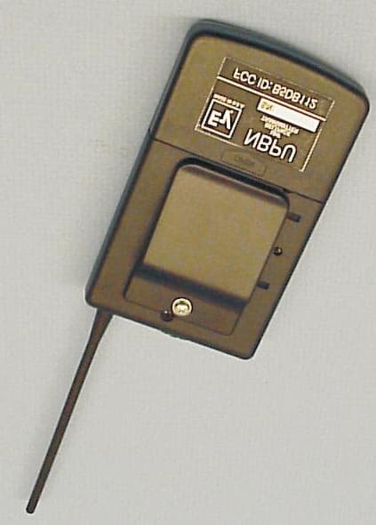
Click to zoom
Application Details
- Equipment Class
- TBT - Licensed Broadcast Transmitter Worn on Body
- Date of Grant
- Feb 23, 2000
- Application Purpose
- Original Equipment
- Date of Application
- Nov 30, 1999
- Equipment Note
- Beltpack Wireless Microphone Transmitter
- Frequency Range
- 518.00000000 - 806.00000000
- Company
- Bosch Security Systems, Inc.
- Country
- United States
Documents & Files
Document Text
Text extracted from the exhibit documents filed with the FCC. Open a document above to read the original.
Users Manual
TELEX Owners Manual/Operating Instructions Telex Evi Model NBPU UHF Transmitter General...... The Telex Evi NBPU is a 10 Channel Belt Pack Transmitter operating within the UHF frequency range. ( 518.0 to 806.0 MHz ) The transmitter is especially suited for use wherever a small, reliable Belt Pack wireless transmitter is required. Guitar/Instrument versions are available. Please note that each transmitter requires a matching receiver with the same operating frequency group. Standard “off the shelf” frequencies are available. Please see the Telex Price List for information. The Telex Evi NBPU Series feature 10 channel versatility as well as economy. SETUP: Before setting up the transmitter, it is necessary to set up the receiver or at least check the receiver operation if the receiver has been installed previously. Place the receiver in an area with the antennas in clear view of the transmitter operating area. Connect the receiver audio output to the audio input of the mixer, amplifier or other device. Turn the input to these items down at this point. Apply power to the receiver. Set the receiver channel to match the transmitter setting. Note that there should be no "Carrier" or TX light on at the receiver at this time. If there is a light on, this indicates RF interference to the channel and the interference must be eliminated or you should consider changing the channel frequency. TELEX Evi NBPU Page 2 If the interference is not severe, suitable operation can sometimes be made possible by adjusting the squelch control until the light goes off. (Transmitter off) If the light cannot be made to go off by adjusting the squelch control, then the channel should be abandoned. Set the receiver audio output control to its midpoint (50 % of rotation). Set the audio device volume control to its normal setting. Open the transmitter battery door and install a fresh 9 volt alkaline battery. Place the transmitter in the position desired and turn on the power switch. The Green battery light should flash once and go off. The carrier light at the receiver should now be on. You are now ready to use the microphone. Place the transmitter Audio Switch in the ON position (up). Talk in your normal tone and volume or operate the instrument, as required. If the Red light on the transmitter comes on or continues to flash as you speak or play, turn down the transmitter gain control until the Red light is off or only flash’s on occasion. If the audio to the mixer or amplifier sounds distorted or clipped, try reducing the input volume of the mixer or amplifier, or turn the volume down on the receiver. FCC REGULATIONS The Telex EVi Model NBPU is Type Accepted under United States Federal Communications Part 74. Licensing of Telex equipment is the users responsibility and licensibility depends upon the users classification and the frequency selected. Telex strongly urges the user to contact the appropriate telecommunications authority before ordering frequencies other than factory preset frequencies. CAUTION: Changes or modifications made by the user could void the users authority to use the equipment. TELEX Evi NBPUPage 3 INDUSTRY CANADA INFORMATION Operation is subject to the following two conditions: (1) This device may not cause interference, and (2) this device must accept any interference, including interference that may cause undesired operation of the device.
Block Diagram
LOW PASS FILTERAMPLIFIERAMPLIFIERAMPLIFIEROSCILLATOR LIMITER MODULATION COMPRESSORPRE-EMPHASISAMPLIFIER SWITCHPLL MICROPROCESSOR 4 MHZ CHANNEL SWITCH MIC IN NBPU BLOCK DIAGRAM 518 TO 806 MHZ CHG.NO.DATEAPPD A SIZECODE IDENT 57010 SHEET: DWG. NO. REVISIONS DESCRIPTION SPECIFICATION hy-gain O RO R TELEX TELEX COMMUNICATIONS INC. Lincoln Nebraska U.S.A This drawing, written description or specification Lincoln, NE., and shall not be released, disclosed, represents a proprietary product of TELEX, nor duplicated without the written permission of TELEX QTYDESCRIPTION UNSPECIFIED LIMITS OF TOLERANCE FRACTION: MACHINED FINISH: 64 DECIMAL: .X = .050 IN - + .XX = .030 IN - + .XXX = .010 IN - + O - + O - + ANGLES 1 , BENDS 2 STRAIGHTNESS AND/OR FLATNESS .005 IN./1 IN. CONCENTRICITY .010 TIR O UNMARKED ANGLES, BENDS AND INTERSECTIONS 90 THREADS- EXT. CLASS 2A INT. CLASS 2B NEXT ASSY.USED ON APPLICATIONS DATE DR BY CHK BY APPD. PROD. MATERIAL: ITEM PART NO. SCALE: TITLE LTR NBPU ACTIVE DEVICES DES DEVICE FUNCTION 1. Q1 ZVN4106 Variable resistor 2. Q2 ZVN4106 Variable resistor 3. Q3 MMBT3904 Rectifier 4. Q4 MMBT3906 Rectifier 5. Q5 MMBT3906 Current mirror 6. Q6 MMBT3906 Current mirror 7. Q7 MMBR901 Amplifier 8. Q8 MMBR901 Amplifier 9. Q9 MMBT3904 Switch 10. Q10 MMBT3906 Current source 11. Q11 MMBR901 Amplifier 12. U1 LM833 Amplifier / Comparator 13. U2 NE570 Compressor / Voltage regulator 14. U3 AT90S1200 Microprocessor 15. U4 TRF2050 PLL
Cover Letter(s)
Correction for EA96125 From:Telex Communications INC. Charlie Conner In fillling out form 731, item 3 today, FCC Grantee Code B5D was repeated in error in the Equipment Product Code section. Now reads B5DB5DB112. Should Read B5DB112. Please correct for me. Also, the EA assignment is EA96125. Thanks for your help and sorry to create the error. Regards, Charlie Conner
ID Label/Location Info
ID LABEL / LOCATION INFO
Operational Description
NBPU Operational Description A. Audio Input from the microphone is amplified by U1B. VR1 is user adjustable and varies the gain from 0 to 40 dB. C12, R21 and R22 provide pre-emphasis at 50 microseconds. U2A is a 2:1 compressor that is used for noise reduction. A modulation limiter is formed by Q1-Q6 and associated components. Q4 detects positive audio peaks and negative peaks are handled by Q3, Q5, and Q6. The resulting current charges C8 and turns on Q1 and Q2, attenuating the incoming audio. VR2 is used to set the frequency deviation. B. RF Output HY1 is a VCO that runs at the output frequency. No multiplication takes place in the RF chain. Q7, Q8, and Q11 buffer and amplify the carrier. C45, C46, C47, L8 and L9 form a matching network and low pass filter. Q10 is used to control the current through the amplifier section. Q9 is used to switch the amplifier on after the synthesizer achieves lock. C. Synthesizer U4 is a PLL that is serially loaded from microprocessor U3. U3 monitors S3, the channel selection switch, and loads new data into U4 if the switch is changed. RF from the VCO is fed to the PLL via C32 and R34. L10 removes reference components coming out of U4. Y1 provides the reference frequency for U4. VC1 is used to set this to exactly 4 MHz. U4 controls the VCO through the loop filter consisting of R35, R36, C29 and C30. Modulation is fed to the bottom of C29.
Parts List/Tune Up Info
770597a.rep NBPU PARTS LIST Bill of Materials 770597A.S01 Quan Type Value Ref Designators ======================================================================== 1 1200B AT90S1200 U3 1 570AC NE570 U2 1 7025 TRF2050 U4 1 9DA LM833 U1 1 C .0015UF C12 4 C 100PF C16,C3,C44,C49 6 C .1UF C20,C25,C26,C27,C5,C8 1 C 22PF C21 1 C 33PF C22 11 C .001UF C23,C24,C28,C30,C34,C37, C40,C41,C42,C43,C51 1 C 10PF C32 1 C 5.6PF C33 1 C NO PART C35 1 C 12PF C36 1 C 1.5PF C38 01-Dec-99 09:37 Page 1 Bill of Materials 770597A.S01 Page 1 770597a.rep Quan Type Value Ref Designators ======================================================================== 2 C 3.9PF C39,C47 1 C 1PF C45 1 C 3.3PF C46 1 C * C50 1 C 47PF C6 10 CE 10UF C1,C10,C13,C14,C19,C2, C29,C4,C7,C9 1 CE .22UF C11 3 CE 1UF C15,C17,C31 1 CE 2.2UF C18 1 CV 5-20PF VC1 1 D 1N5817 D1 1 DD2 BAV99 D2 2 DL VAL DS1,DS2 5 E VAL E1,E2,E3,E4,E5 7 LA .22UH L1,L10,L2,L3,L5,L6,L7 01-Dec-99 09:37 Page 2 Bill of Materials 770597A.S01 Quan Type Value Ref Designators ======================================================================== 2 LA 8NH L4,L9 Page 2 770597a.rep 1 LA 27NH L8 1 P + B1 1 P - B2 3 QNEBC MMBR901 Q11,Q7,Q8 2 QNEBC MMBT3904 Q3,Q9 2 QNT ZVN4106 Q1,Q2 4 QPEBC MMBT3906 Q10,Q4,Q5,Q6 1 R 3.01K R1 6 R * R10,R21,R22/C48,R3,R50, R51 7 R 1K R11,R15,R16,R17,R18,R19, R20 7 R 10K R12,R14,R30,R31,R38,R7, R8 1 R 3.9M R13 2 R 475 R2,R35 01-Dec-99 09:37 Page 3 Bill of Materials 770597A.S01 Quan Type Value Ref Designators ======================================================================== 1 R 24.3K R23 2 R 4.99K R26,R29 1 R 13K R27 Page 3 770597a.rep 1 R 16.2K R28 1 R 150K R32 1 R 511K R33 2 R 221 R34,R52 2 R 4.75K R36,R46 2 R 47.5 R37,R40 2 R 47.5K R39,R6 2 R 100 R4,R42 1 R 22.1K R41 1 R 22 R43 1 R 6.81K R44 2 R 100K R45,R9 01-Dec-99 09:37 Page 4 Bill of Materials 770597A.S01 Quan Type Value Ref Designators ======================================================================== 1 R 10 R47 1 R 26.7 R48 1 R 20K R5 1 RS * R49 1 RVA 100K VR1 Page 4 770597a.rep 1 RVA 100 VR2 1 S10 VAL S3 2 SSS VAL S1,S2 9 TP TP1,TP2,TP3,TP4,TP5,TP6, TP7,TP8,TP9 1 VCO-500SQ VAL HY1 1 Y 4MHZ Y1 Total Parts: 153 01-Dec-99 09:37 Page 5 Page 5 NBPU ALIGNMENT PROCEDURE 1. Set channel switch to 0. Set mic gain (VR1) max CW. 2. Feed 7.8mV at 1 kHz across E2 (hot) and E1 (gnd). 3. Connect a frequency counter and deviation meter from E5 (rf out) to ground. 4. Connect the battery contacts to 9 volts DC. 5. Turn unit on and adjust VC1 for the channel 0 frequency. 6. Adjust VR2 for +/- 40 kHz deviation.
Schematics
* R51 * C50 4.99K R29 S3 C 8 4 2 1 AT90S1200 U3 13 45 19 18 17 1 10 9 6 7 8 2 12 14 11 20 10K R31 4MHZ Y1 5-20PF VC1 22PF C21 33PF C22 HY1 Vs VtRF 15 3 7 TP7 TP6 TP5 TP4 10K R30 TP8 .1UF C20 BAV99 D2 S2 TP2 + - TP3 C31 1UF + C2 10UF + .001UF C23 47.5 R37 100 VR2 .1UF C8 E3 E1 C1 10UF + R4 100 16.2K R28 NE570 U2:B 1.8V 20K 5 6 7 R27 13K .1UF C5 47.5K R6 20K R5 10K R7 R8 10K R10 * C7 10UF + 1K R11 U1:A LM833 1 8 3 2 LM833 U1:B 5 6 7 4 VR1 100K 10UF C9 + Q3 MMBT3904 R19 1K R16 1K R20 1K 10UF C10 + ZVN4106 Q1 ZVN4106 Q2 DS1 R12 10K R13 3.9M 100PF C3 R9 100K R14 10K E2 .001UF C30 4.75K R36 47.5K R39 10K R38 R41 22.1K .001UF C24 MMBT3904 Q9 R45 100K L7 .22UH C44 100PF C43 .001UF .1UF C26 C29 10UF + 475 R35 C33 5.6PF R40 47.5 Q7 MMBR901 R42 100 C34 .001UF C36 12PF R43 22 Q8 MMBR901 R44 6.81K L4 8NH C38 ** L3 .22UH C37 .001UF C39 3.9PF R47 10 Q11 MMBR901 Q10 MMBT3906 C42 .001UF R48 26.7 L5 .22UH C40 .001UF C47 ** .1UF C25 150K R32 .1UF C27 R33 511K .001UF C28 C41 .001UF R46 4.75K C45 ** C46 ** L8 27NH L9 8NH .22UH L6 U4 TRF2050 3 2 1 8 18 13 5 6 7 14 20 19 15 101217164 47PF C6 E5 TP9 .22UH L2 R2 475 10UF C4 + DS2 1K R15 .22UH L1 R3 * R1 3.01K E4 100PF C49 L10 .22UH C32 10PF R34 221 R18 1K Q5 MMBT3906 R17 1K MMBT3906 Q4 Q6 MMBT3906 S1 4.99K R26 C19 10UF + C18 2.2UF + C17 1UF + TP1 100PF C16 U2:A NE570 1.8V G 20K 10K 30K 11 20K 15 14 10 12 1694 GND 13 VCC C15 1UF + 24.3K R23 1N5817 D1 C14 10UF + C13 10UF + R50 * * R22/C48 R49 * * R21 .22UF C11 + C12 .0015UF C35 ** R52 221 .001UF C51 RB 12/01/99 DDN 12/01/99 * MODEL TABULATION NBPU 10 CHNL 770597 770597 RB 7/6/99 REFERENCE DESIGNATOR 2.7PF 3.9PF 1.8PF 1.2PF 2.2PF 1.8PF 1.5PF 1.2PF 1.0PF 6.8PF 5.6PF 4.7PF 3.9PF 3.3PF 4.7PF 4.7PF 3.9PF 3.9PF 3.9PF REFERENCE DESIGNATOR --- ** FREQUENCY TABULATION US FREQ. RANGE 518-566MHz 566-620MHz 620-680MHz 680-752MHz 752-806MHz 680-752MHz 620-680MHz 566-620MHz FREQ. RANGE 512-566MHz 752-825MHz R.O.W. 47.5K 200K0 OHM 0 OHM 30.1K R10R21 10K 26.7K R22/C48 6.65K .01UF NO PART R49R50 35.7K R51 0 OHM C35C38C45C46C47 2.7PF 2.7PF 2.2PF 1.8PF 1.5PF .1UF NO PART GUITAR VOICE MODELC50 10K R3 NO PART ARELEASED11/24/99SBC SYNTHESIZED TRANSMITTER REFERENCE PCB 750503 879229-ALL(SMT) 879230-ALL(TH) NBPU NOTES: REVISIONS DESCRIPTIONLTRCHG NODATEAPPD UNSPECIFIED LIMITS OF TOLERANCE DECIMAL: .X .XX .XXX FRACTION: - MACHINED FINISH: 64 + - + oo - - + + + - INT. CLASS 2B THREADS- EXT. CLASS 2A AND INTERSECTIONS 90 o UNMARKED ANGLES, BENDS CONCENTRICITY .010 TIR FLATNESS .005 IN./1 IN. STRAIGHTNESS AND/OR ANGLES 1 : BENDS 2 APPLICATIONS SCALE CODE IDENT 57010 DWG.NO. DESIGNATOR MATERIAL: TITLE SIZE SHEET DATE DR BY CHK BY APPD. PROD ITEM USED ON NEXT ASSY. TELEX. nor duplicated without the written permission of Lincoln, NE., and shall not be released, disclosed, represents a proprietary product of TELEX, This drawing, written description or specification Lincoln Nebraska U.S.A TELEX COMMUNICATIONS INC. PART NO QTYDESCRIPTION = .010 IN = .030 IN = .050 IN 1234 SHEET REV STATUS REV SHT D O R TELEX
Contact Information
Applicant
James R Andersen(Principal Electrical Engineer)
Technical Specifications
| # | Rule Parts | Frequency Range | Power Output | Emission | Tolerance |
|---|---|---|---|---|---|
| 1 | 74.861 | 518 MHz - 806 MHz | 10.00 mW | 180KF3E | 15.0000000000 ppm |
Other Applications from Bosch Security Systems, Inc.

B5DM540
Jun 02, 2020Wireless microphone base station
Equipment Class
TLD - Licensed LPAS Device
B5DM542
Jun 01, 2020Wireless beltpack
Equipment Class
TLD - Licensed LPAS Device
B5DM541
May 27, 2020Wireless beltpack
Equipment Class
TLD - Licensed LPAS Device
B5DM536
Mar 18, 2020Single Receiver UHF Wireless Intercom Beltpack
Equipment Class
TLD - Licensed LPAS Device
B5DM539
Mar 18, 2020Dual Receiver Narrowband UHF Wireless Intercom Beltpack
Equipment Class
TLD - Licensed LPAS Device