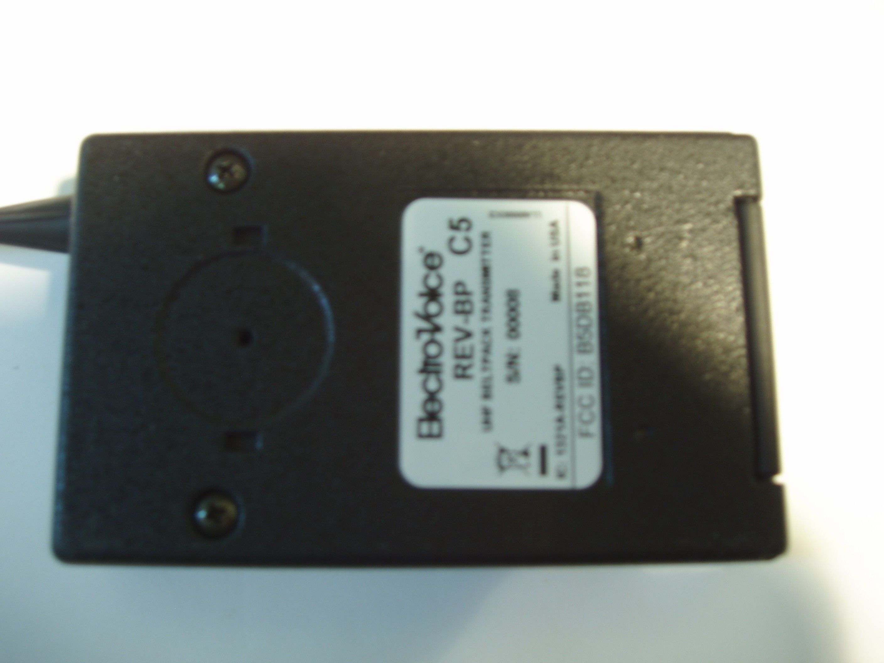
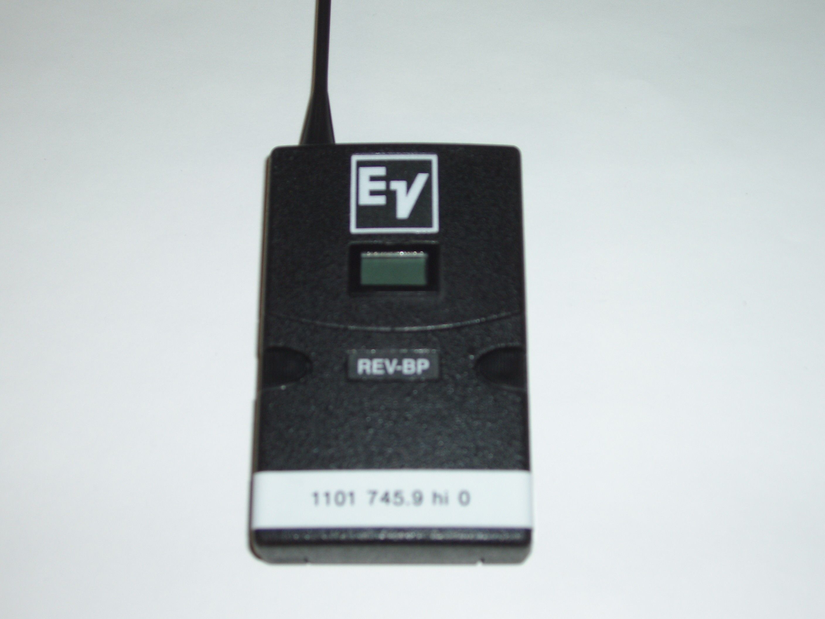
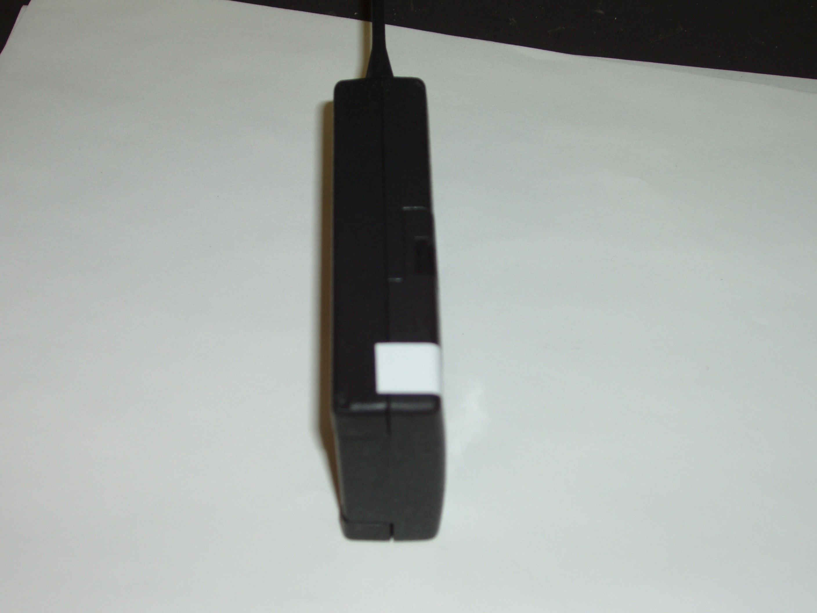
B5DB118UHF BELTPACK TRANSMITTER
Bosch Security Systems, Inc.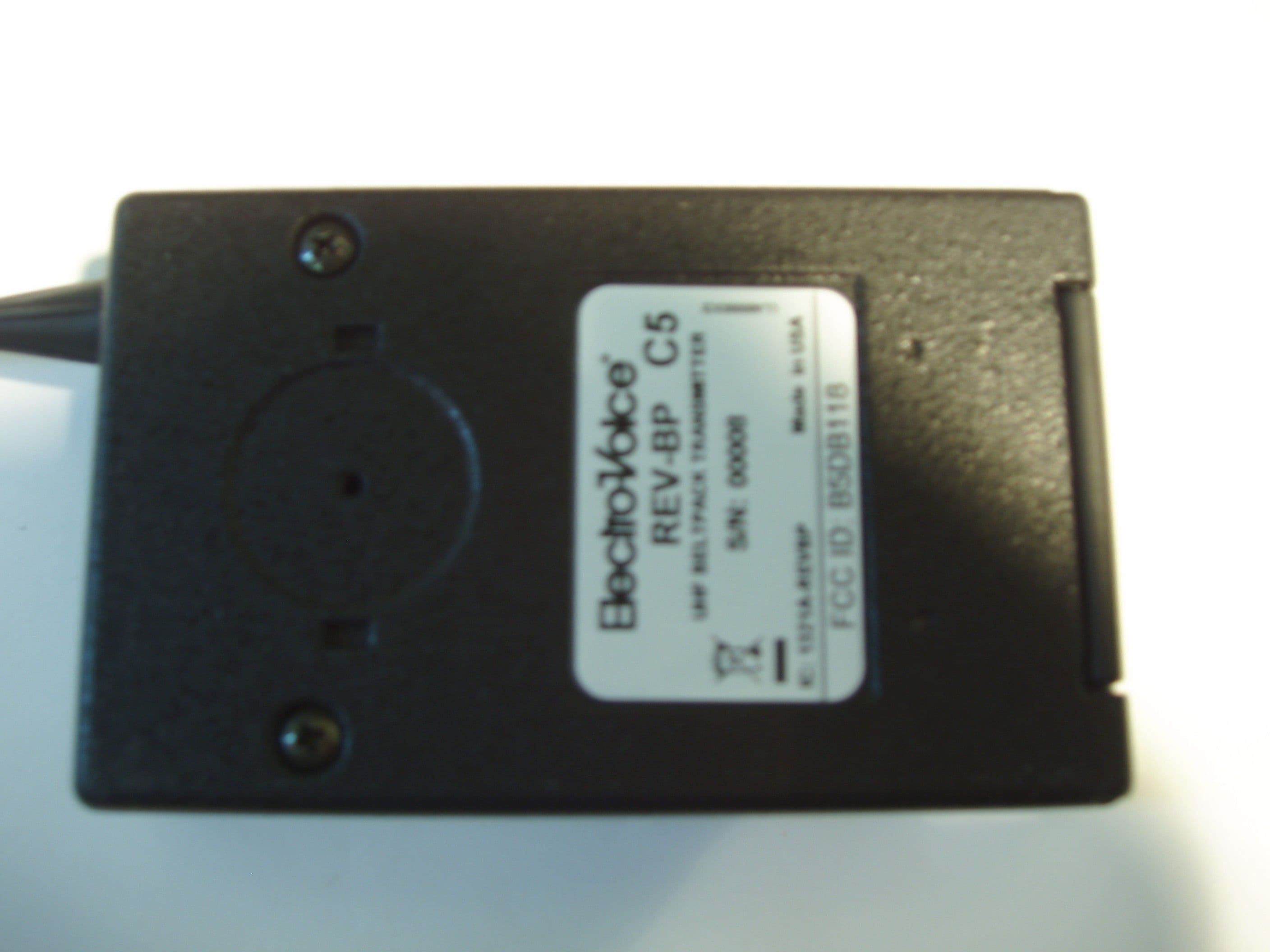
Click to zoom
Application Details
- Equipment Class
- TNT - Licensed Non-Broadcast Transmitter Worn on Body
- Date of Grant
- Jan 02, 2007
- Application Purpose
- Original Equipment
- Date of Application
- Dec 28, 2006
- Equipment Note
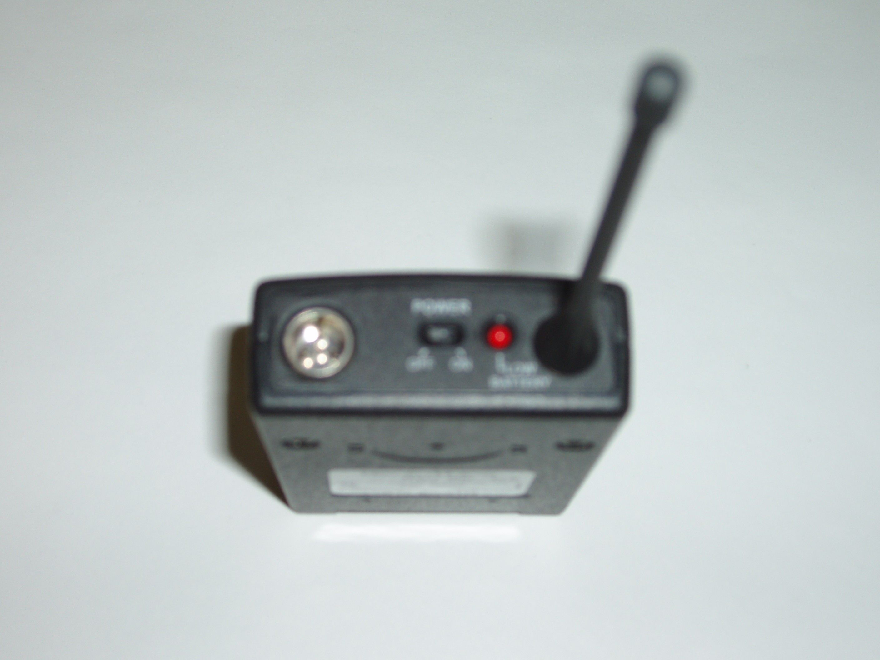
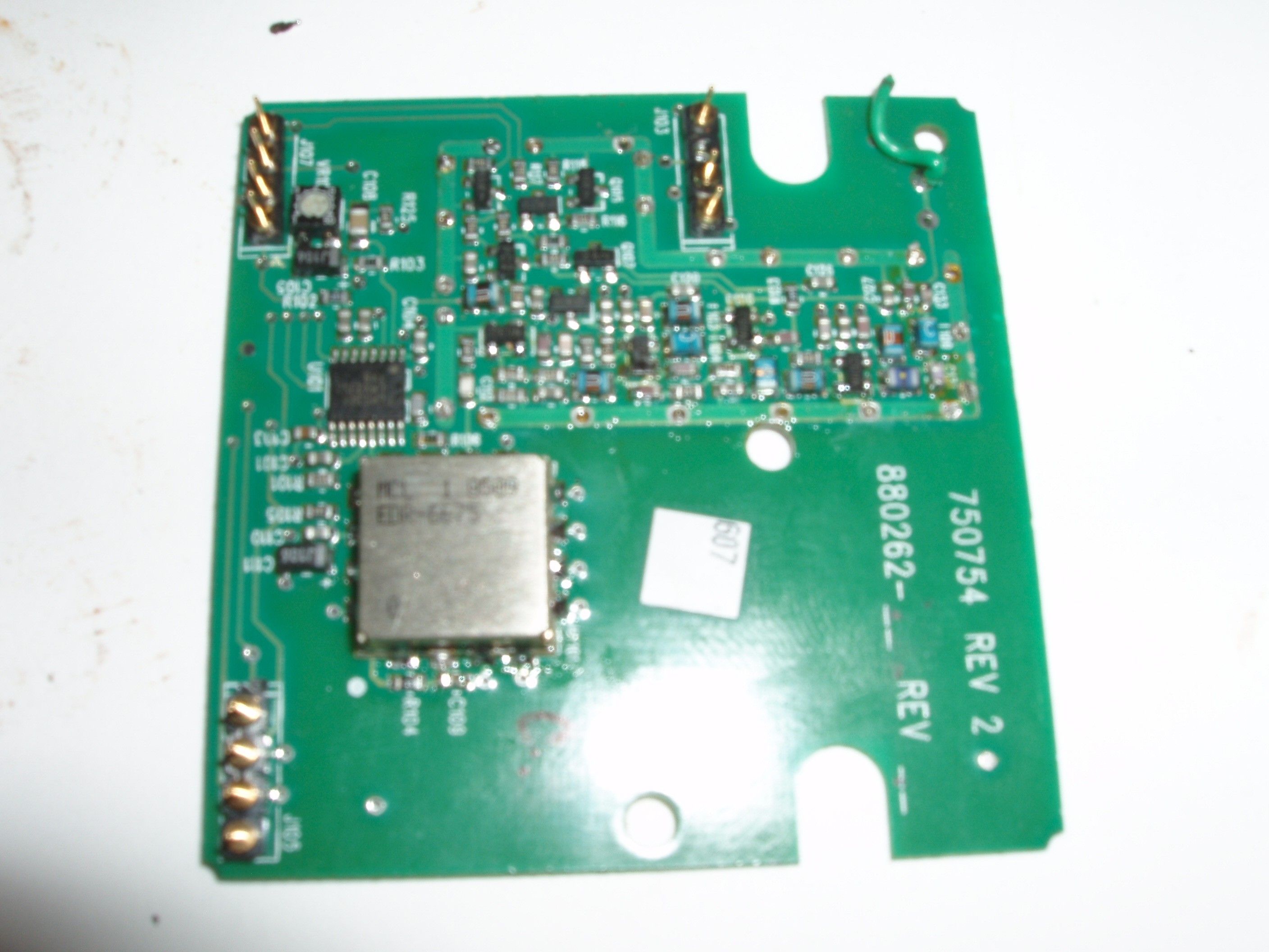
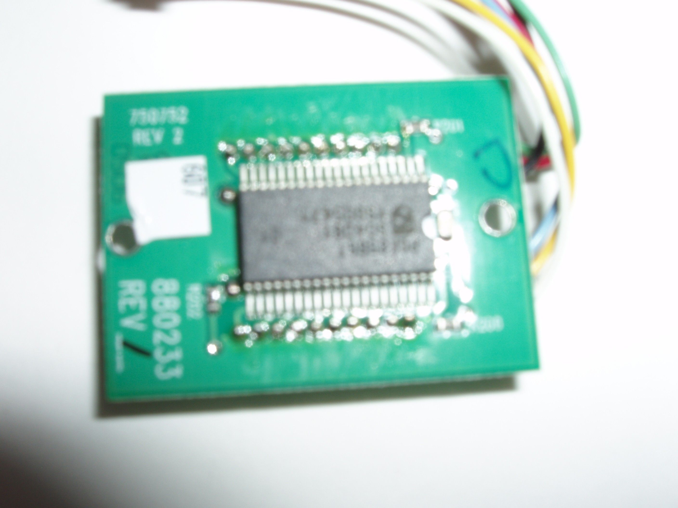
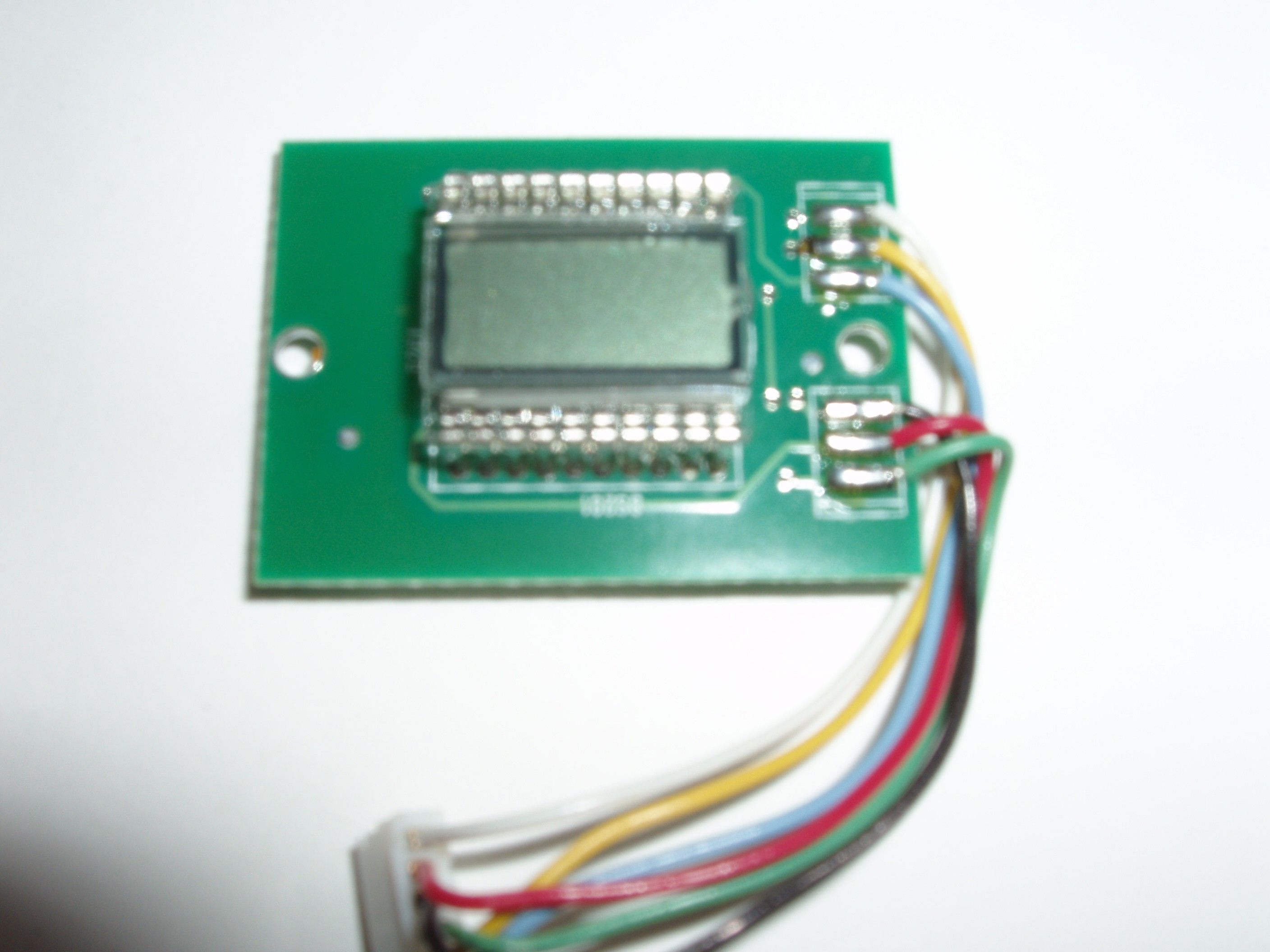
- UHF BELTPACK TRANSMITTER
- Frequency Range
- 614.10000000 - 746.00000000
- Company
- Bosch Security Systems, Inc.
- Country
- United States
Documents & Files
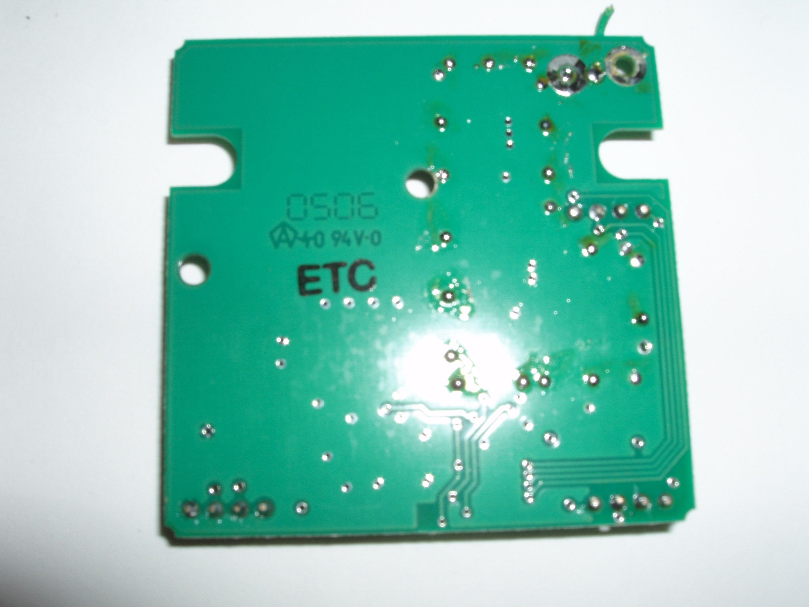
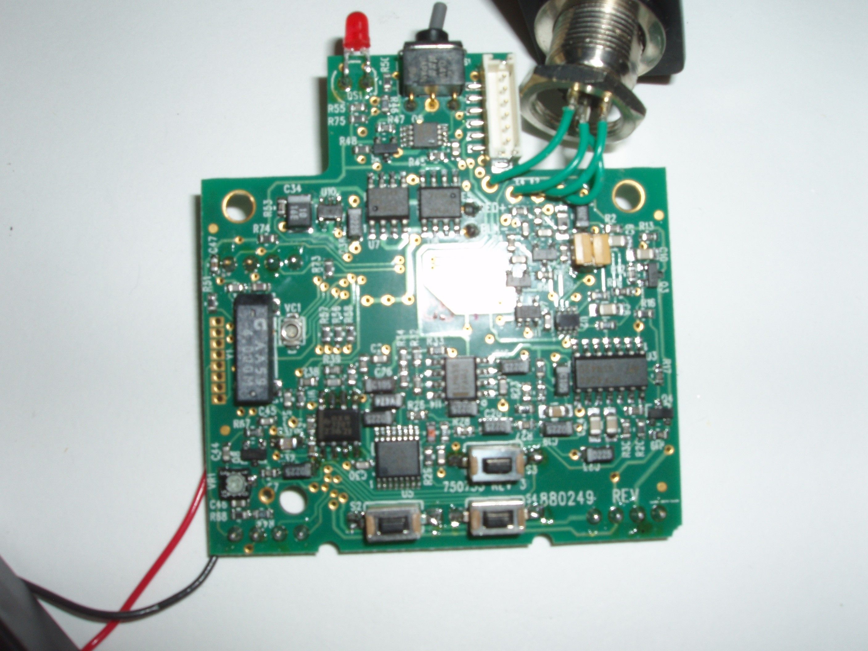
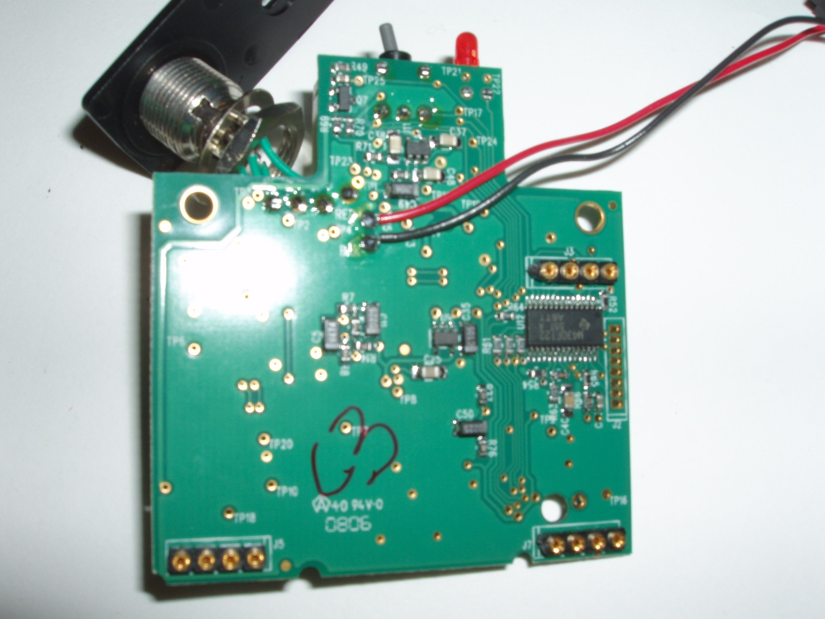
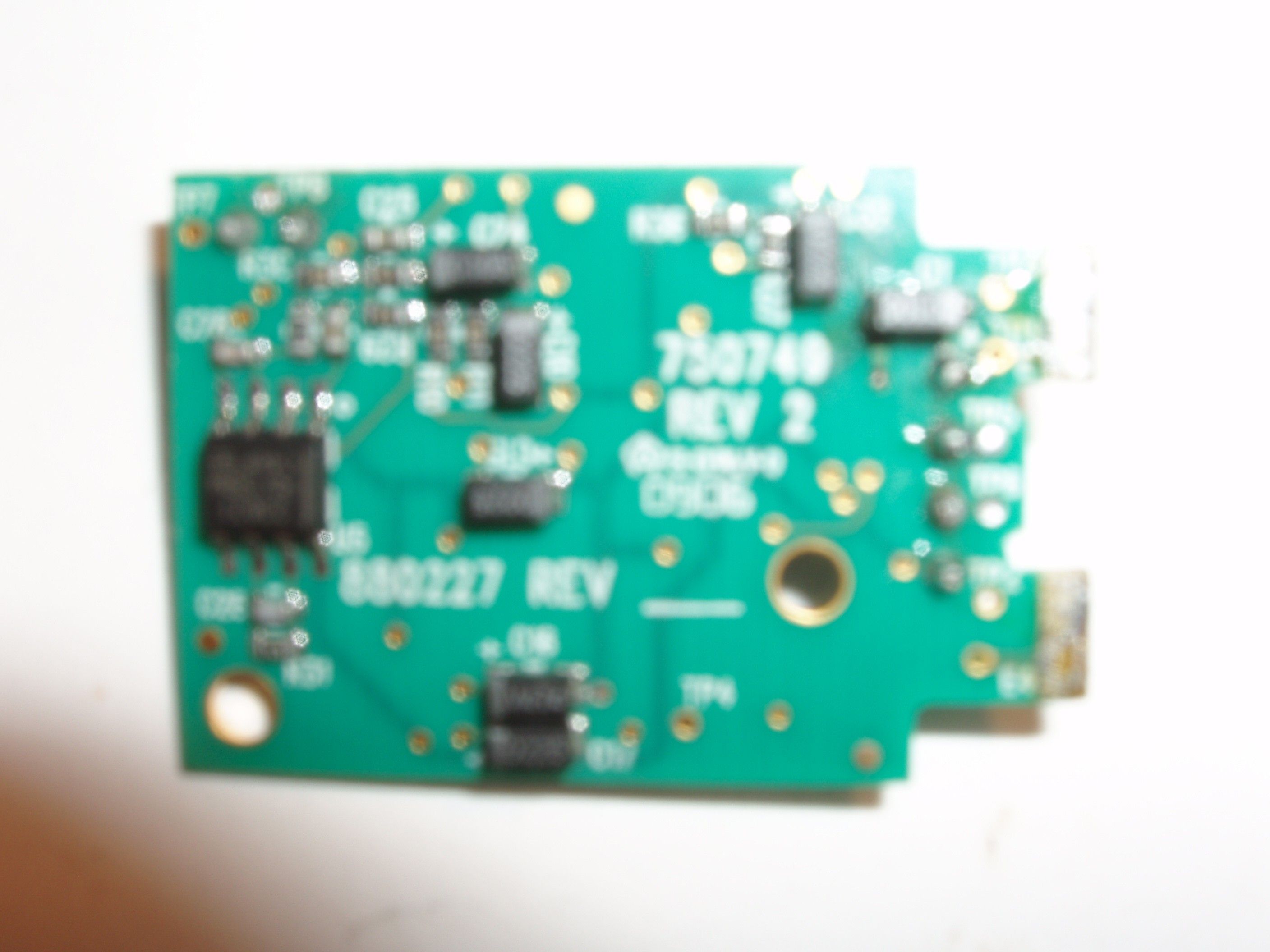
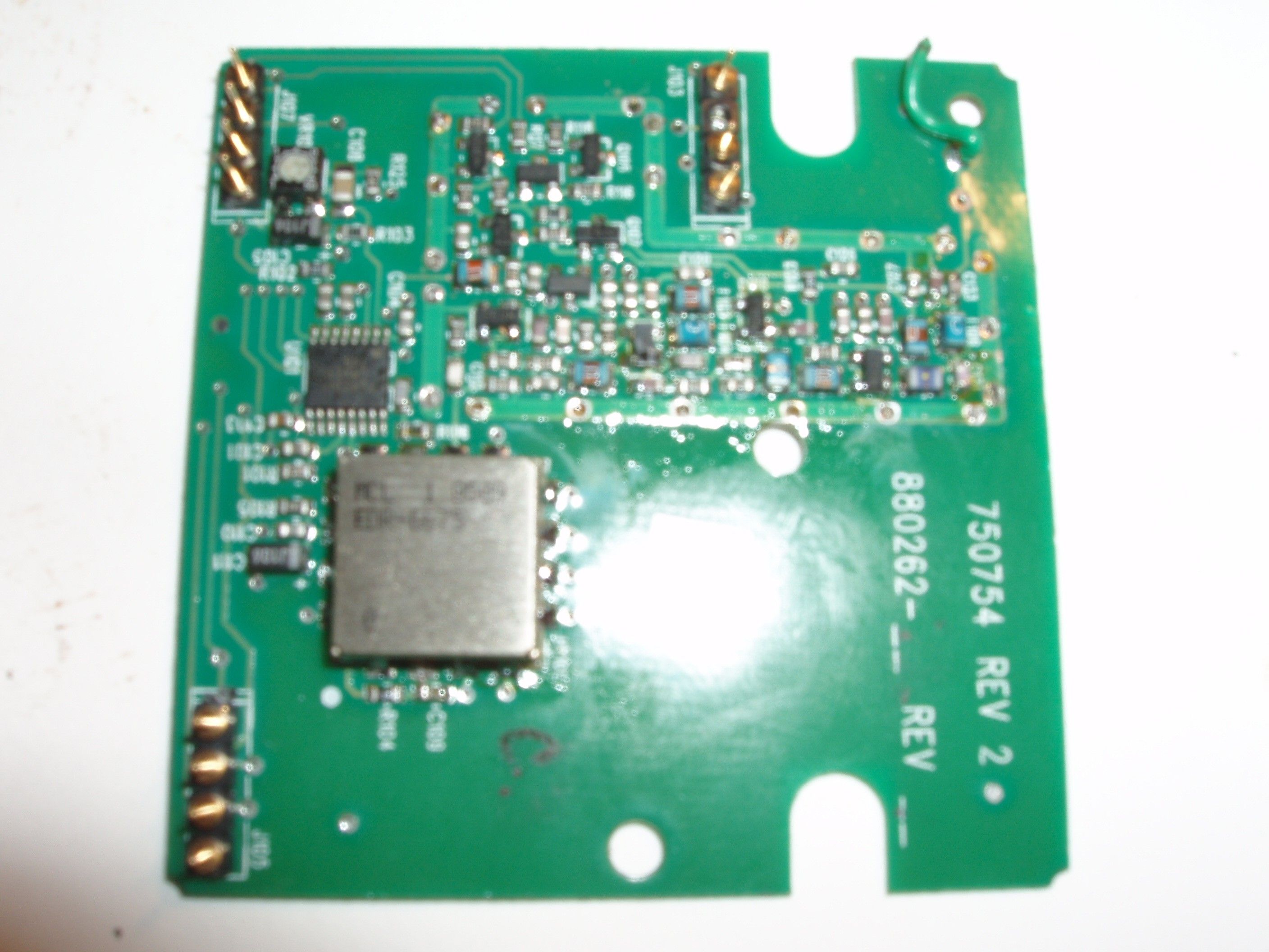
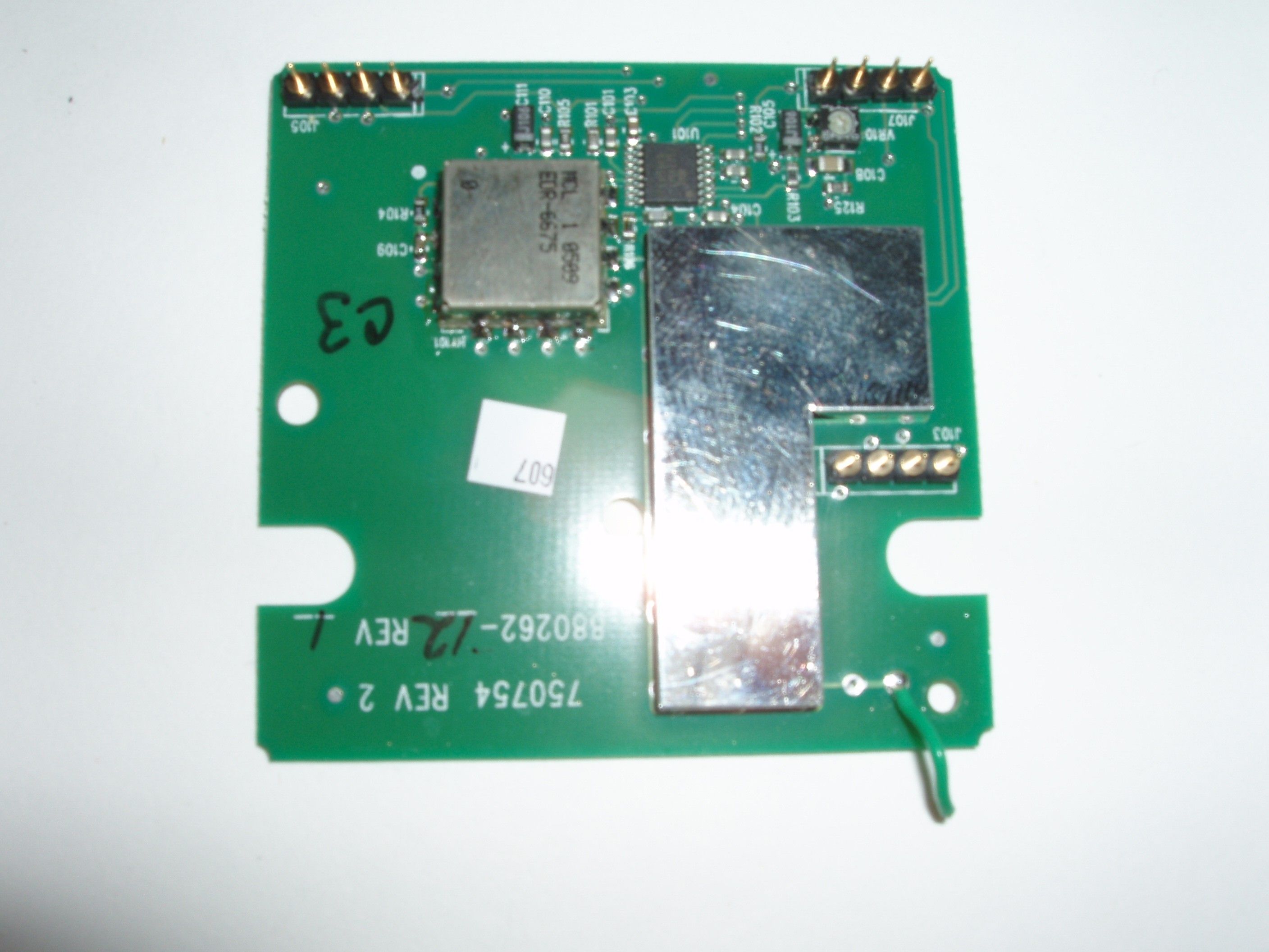
Document Text
Text extracted from the exhibit documents filed with the FCC. Open a document above to read the original.
Users Manual
Preliminary Users Manual Electro-Voice Model REV-BP Wireless Microphone Transmitter The Electro-Voice (Ev) REV-BP is a Professional Grade Wireless Beltpack Transmitter operating in the UHF frequency range. The REV-BP combines frequency agility and ease of use like no other. The transmitter operates within a 24 MHz wide segment in 25 KHz steps. The high quality audio circuitry and advanced Radio Frequency (RF) signal processing offer broadcast quality signal-to-noise and audio clarity. System features include: • Durable Painted Metal Case. • TA-4F Audio Connector. • Permanent Flash Memory for frequency/setting storage. • On-Loc prevents accidental power off (when set). • LCD Display for ease of viewing. • Flexible quarter wave screw-on Antenna. Quick set-up: 1. With the Power Switch on the transmitter OFF, install a fresh battery into the transmitter. 2. To prevent feedback or unintentional noise, mute the audio mixer/amplifier or other device during set-up adjustments. Place the transmitter Power Switch to the ON position. 3. The Battery light near the Off/On switch will flash once and then go off. The display will also come on briefly displaying the current frequency group and channel and the battery level. Note: Anytime Power is removed and turned back on, the GP/CH/Bat screen will be displayed. REV-BP Users Manual Page 2 Quick set cont’d. 4. The screen will stop at the GP (Group) and CH (Channel) screen. If the Group and Channel match the desired receiver group and channel, Proceed to Step 9. If not, proceed to Step 5. 5. To select a different GP/CH, press SET one time. The Group will start flashing. Use the up and down arrows to change the group number. Press the SET button to save the Group. After setting the Group, The Channel number will start flashing . Use the up/down arrows to change the Channel number. Press SET and the channel is now saved. There are 10 Groups and up to 16 Channels (preferred groups/channels) stored in memory. If desired, you can create new groups/ channels but you must change to a new frequency to store in that group/channel. In order to select a new frequency, you must have a “users” group /channel selected. Press the SET button. The Group should be flashing. Press the Up arrow until a group ending with u is found (any u group can be used) Press SET. The Channel should now be flashing. Select a channel with the up/down arrow. Press SET. You are now ready to select a frequency to store in the users group above. Press and hold the set and down arrows at the same time for 3 seconds and release to go to the next screen function. 8. The next screen displays the operating frequency of the group/channel. If there is no frequency currently stored in the selected users group/channel, a dashed line will be shown. Press SET. The dashed line or frequency will start flashing. Press the up arrow one step at a time to find the desired frequency or hold down the up arrow to scroll through the frequencies quickly. The frequencies can be scrolled either way by the up/down buttons. When the desired frequency is showing, press SET. REV-BP Users Manual Page 3 Quick set cont’d. 9. Press and hold the set and down arrows at the same time for 3 seconds and release to go to the next screen function. The next screen is the audio (microphone/instrument) level (attenuator) screen. Setting the levels correctly depends on the microphone or instrument used and the person using the microphone. Setting the attenuator to “0”db is the same as setting a control to maximum gain. Setting the attenuator to –42 db is the same as setting a control to minimum gain. Each step of the attenuator equals 3 db. Setting the attenuator for the maximum Audio Meter reading on the receiver without peak distortion will produce the best signal to noise ratio. 10. The next screen is RF Power. The Transmit Power (RF) is shipped set to “Lo” for use with multiple frequency systems and the best battery life. “Hi power can be selected for longer distances or to suppress noise or interference. The nominal power in Hi is 50 milliwatts. 11. The next screen is Voice or Guitar. The transmitter is shipped set to Voice. To select guitar when in the voice screen, press SET. The screen flash’s, press the Up arrow and the screen will change to “Gui tAr”. Press SET. The transmitter is now in guitar mode. To return to Voice (in the “gui tAr”screen) Press SET, the screen flash’s, press the Down arrow, the screen changes to flashing Voice, Press SET, flashing stops. The transmitter is now in Voice mode. 12. When power off is required, simply place the power Off-On switch in the OFF position. The display will then delay slightly to allow the receiver to shut down quietly. Specifications: Page 4 RF Frequency range........................614.0 to 746.0 MHz. RF Channel Step................................ 25 KHz RF Power....................................Norm, 5 mW, High, 50 mW. Modulation..................................FM, 40 KHz nominal. Audio Frequency Response...............80-15000 Hz +/- 2 dB. Audio attenuator Range....................42 dB. Microphones, Electret or Dynamic...... Electret bias provided. Antenna......................................Quarter Wave Flexible. Battery Life (Alkaline)..................... 8-10 Hours Typical. Approval Information: The Telex/Ev REV-BP Transmitter is Type Accepted under United States Federal Communications Commission Part 74. The Telex/Ev REV-BP Transmitter is Certified to Industry Canada RSS123 rules. Licensing of Telex/Ev equipment is the users responsibility and licensability depends upon the user’s classification, user’s application and frequency selected. Telex/Ev strongly urges the user to contact the appropriate telecommunications authority for any desired clarification. CAUTION: Any changes or modifications made to the above equipment could void the user’s authority to operate the equipment.
Cover Letter(s)
Celltech Labs Inc. 1955 Moss Court, Kelowna, B.C. Canada V1Y 9L3 Tel. 250-448-7047 • Fax. 250-448-7046 • e-mail: [email protected] www.celltechlabs.com December 20, 2006 Federal Communications Commission Authorization and Evaluation Division Equipment Authorization Branch 7435 Oakland Mills Road Columbia, MD 21046 Attn: Kwok Chan SUBJECT: Telex Communications, Inc. Response to FCC Comments FCC ID: B5DB118 Dear Kwok, On behalf of Telex Communications, Inc. is our response to your comments dated December 18, 2006 requesting additional information for the subject application. 1. Clarify discrepancies of ConvF at 900 MHz in incoming inquiry: 6.04 vs. 6.47? Probe calibration frequency (ConvF): 6.7 at 650MHz +/- 50MHz 6.4 at 750MHz +/- 50MHz 6.04 at 900MHz +/-100MHz vs. analysis of ConvF of probe at dipole and probe calibration (device freq.) must show SAR variation <5% (e.g. SAR system manual) _OK_ (dipole ConvF=6.47, probe 750MHz ConvF=6.4, probe 650MHz ConvF=6.7). Celltech Response The system validation document with probe ConvF 6.47 shown in Appendix E of the SAR report was submitted inadvertently and does not apply to the evaluation. The applicable system validation with ConvF 6.4 (750 MHz) and 6.7 (650 MHz) is shown in Appendix B of the SAR report. Please refer to Appendix B of the revised SAR report (Rev. 1.3) submitted with this response. 2. SAR target values in the SAR report are identified as IEEE targets; however, it appears SPEAG targets are used. IEEE targets at 835 MHz and 1 W is 9.7 W/kg. SPEAG target is lower (about 9.5); however, it may also vary slightly from dipole to dipole. Such discrepancies are found on pages 8, 22, 25 (please check other pages too), which will affect other related information on these pages (15%, dev etc. and it is unclear what this 15% represents). Celltech Response The SAR target values listed on pages 8, 22 and 25 of the SAR report are both the SPEAG target and IEEE target. The IEEE target for 1 Watt at 835 MHz is 9.7; so also is the SPEAG target 9.7 for 1 Watt at 835 MHz. Please refer to Table 1 on page 8 of the revised SAR report (Rev. 1.3) submitted with this response listing the SAR system manufacturer’s reference body SAR values at 835 MHz. 3. Probe calibration certificate indicates 7% standard deviation for calibrations at 650 and 750 MHz. Incorrect information has been used in the uncertainty table on page 13. Note: k=2 is used for experimental calibration but standard deviation is used for numerical calibration. Celltech Response The SAR report was inadvertently submitted listing the probe uncertainty value as k=2 for 650 MHz and 750 MHz on pages 13 and 14. Please refer to the revised SAR report (Rev. 1.3) submitted with this response listing the probe uncertainty value on pages 13 and 14 as standard deviation (7%) in accordance with the probe calibration document. 4. The liquid dielectric parameter measurement tolerances indicated in the uncertainty tables on pages 13 and 14 do not match those on page 6. Please also check other entries in the uncertainty tables to ensure correct information are entered. Celltech Response Please refer to the revised SAR report (Rev. 1.3) submitted with this response listing the correct liquid dielectric parameter measurement tolerances in the uncertainty tables on pages 13 and 14. 5. Clarify how the values of 2.9% and 5.1% at the bottom of pages 22 and 25 on estimated SAR changes due to probe ConvF are calculated. Note: The implementation of ConvF on most SAR systems generally follows an inverse relationship to SAR. The Application Note specifies 5%; however, up to 10% may be accepted on a case-by-case basis provided the impact due to tissue dielectric parameters is small; therefore, the total SAR variation is expected to be within 10-15%. Celltech Labs Inc. 1955 Moss Court, Kelowna, B.C. Canada V1Y 9L3 Tel. 250-448-7047 • Fax. 250-448-7046 • e-mail: [email protected] www.celltechlabs.com Celltech Response Formulae used for calculating SAR from measured values taken from DASY4 manual. V = U + U^2(cf/dcp) Where: V = compensated signal of the given channel U = input signal of the given channel Cf = Crest factor of exciting field Dcp = diode compression point In the conversion factor files for 650 MHz, 750 MHz and 900 MHz the dcp is the same. Therefore the compensated signal resulting from any one measurement will be the same if calculated from any other set of conversion factors. E = root(V/(Norm*ConvF)) Where: V = compensated signal of the given channel Norm = sensor sensitivity of given channel ConvF = sensitivity enhancement in solution In the conversion factor files for 650 MHz, 750 MHz and 900 MHz the Norm is the same. Therefore the single deciding factor used for calculation of the SAR from the compensated signal V is the sensitivity enhancement in solution, ConvF. In the following tables, the calculation of E from V, Norm and ConvF are displayed. The Total is performed by root(Ex^2+Ey^2+Ez^2) and the percent difference is calculated and displayed on the bottom line. The 650 MHz measurements calculated manually with the 900 MHz conversion factors given in the probe calibration document expect a 5.32% discrepancy. The 750 MHz measurements calculated manually with the 900 MHz conversion factors expect a 3.74% discrepancy. Please refer to revised SAR report (Rev. 1.3) submitted with this response (pages 22, 25). 650 MHz 900 MHz ConvF 6.7 6.04 Vx 18917.50 18917.50 Vy 4929.09 4929.09 Vz 5249.57 5249.57 Ex 5742.07 6047.67 Ey 1451.99 1529.27 Ez 1546.40 1628.70 Total 6121.36 6447.14 % Diff 0 5.32 750 MHz 900 MHz ConvF 6.5 6.04 Vx 19052.61 19052.61 Vy 5806.42 5806.42 Vz 4951.13 4951.13 Ex 5871.38 6090.86 Ey 1736.55 1801.46 Ez 1480.76 1536.11 Total 6299.31 6534.79 % Diff 0 3.74 Where: Normx = 1.62 Normy = 1.72 Normz = 1.72 Dcp = 92mV 6. (FYI) The dielectric parameters on pages 29 and 30 should have been measured to at least 835 MHz or higher (preferably 900 MHz since probe calibrated at 900 MHz). See beginn…
Text truncated - open the document above for the full version.
Cover Letter(s)
9-12-06 To: Mr. Jon Hartman, M Flom Associates Inc. In response to TCB request for justification that Telex/Ev transmitters are electrically identical throughout the requested frequency range. 1. It should first be noted that Telex Communications Inc. has shown responsibility for its products both to the FCC, M Flom Associates and to its customers by applying for and receiving many Grants over the years. 2. Further, Telex is well aware of its responsibilities and duties such as insuring that its products are made and tested to comply with FCC rules and regulations. 3. Documentation is submitted, as required with each application, showing all components and frequency ranges to be manufactured. These documents are copies of the exact documents that the products are made from. 4. The current applications for transmitter approvals over the frequency range of 614 to 746 MHz have included 3 transmitters for testing representative of that range, one at the low end of the range, one near mid- range and one at the high end of the range. Each transmitter can be set in 100 KHz increments to cover 24 MHz of the requested range. Telex feels that this adequately demonstrates the transmitter capability over the requested range. Moreover, as stated above, all components are clearly shown in the documentation and “identical to” should be evident. Trusting that the above statements are sufficient. Charles E. Conner Project Engineer Telex Communications Inc.
Cover Letter(s)
Telex Communications, Inc. 8601 E. Cornhusker Hwy Lincoln, NE 68507 402-467-5321 Date: September 26, 2002 To: Federal Communications Commission EQUIPMENT APPROVAL SERVICES P.O. Box 358315 Pittsburgh, PA 15251-5315 To: INDUSTRY CANADA Certification & Engineering Bureau 3701 Carling Avenue, Bldg. 94 P.O. Box 11490, Station “H” Ottawa, Ontario, Canada K2H 8S2 Per: 47 CFR 0.457 and 0.459 Re: FCC ID: Model: Pursuant to Sections 0.457 (d) (1) (ii) and 0.459 of the Commission’s Rules, the applicant hereby requests confidential treatment of some of the information accompanying this application as listed below, i.e. Block Diagram, Schematics, Parts Lists, List of Active Devices, Tune-up Procedures (alignment procedure), Operational Description (theory of operation). These materials contain trade secrets and proprietary information not customarily released to the public and the public disclosure of these matters might be harmful to the applicant and provide unjustified benefits to its competitors. The applicant understands that pursuant to Rule 0.457 (d) (1) (ii) disclosure of this application and all accompanying documentation will not be made before the date of the grant of this application. Sincerely, Charles E. Conner Senior Project Engineer Telex Communications, Inc.
Cover Letter(s)
Gretchen Torres From: Bruno Clavier [[email protected]] Sent: Wednesday, November 22, 2006 11:02 AM To: Bruno Clavier Subject: FW: Response to Inquiry to FCC (Tracking Number 158006) SAR probe conversion factor for 74H TELEX 12/29/2006 From: Generic Office of Engineering Technology [mailto:[email protected]] Sent: Wed 11/22/2006 10:33 AM To: Bruno Clavier Subject: Response to Inquiry to FCC (Tracking Number 158006) Inquiry: TIMCO-TCB Request guidance on SAR testing and approval of a Part 74 body-worn tx using an 835MHz reference dipole at offset frequencies. This request is in follow-up of KDB #556330 submitted by Jon Hughes with Celltech Labs. Based on Celltech’s telephone discussion with Kwok Chan on Nov. 3 rd and the Nov. 14 th FCC Application Note “SAR Probe Calibration and System Verification Considerations for Measurements at 150MHz - 3GHz” we are requesting authorization to implement the referenced guidelines and subsequent TCB processing. The following procedure is considered: 1. SAR Probe conversion factors for the testing will be 650 MHz and 750 MHz (numerically assessed by SAR System Manufacturer), 2. SAR System Manufacturer’s Reference Dipole frequency will be 835 MHz and alternative system verification method B will be utilized, 3. SAR evaluation would be performed at the low (614 MHz), mid (680 MHz) and high (746 MHz) frequencies of the test device operating band. The recommended procedures described in the referenced Application Note will be applied and described in the SAR report submittal to TCB. Response: You may proceed with the review provided the following are addressed in both the test report and also during the review: 1. Procedures detailed in the Probe Calibration and System Verification Application Note (AP) are followed and specific items/issued identified in the AP are properly addressed in the test report 2. Two probe calibration frequencies are identified in the inquiry. Which calibration point is used for the SAR measurements? This same calibration point should be used with the required tissue dielectric medium according to alternative system verification method B for system verification with the 835 MHz reference dipole. The tissue dielectric medium property used during the dipole and device measurements should be examined according to those illustrated to attachments 1-3 in the A pplication Note to ensure both probe calibration and tissue medium are adequate within the device test frequency range. If not, both calibration points (650 & 750 MHz) would need to be used and two dipole measurements according to method B would be necessary, according to the tissue medium dielectric parameters dictated by the probe calibrations and routine measurements. It appears the 650 MHz calibration point might be able to cover all three test frequencie! s; and you will have to check the actual probe calirbation and tissue parameters to be sure. 3. The procedues in the Permit But Ask KDB should be followed for any subsequent follow-up requirements before equipment certification is issued. Do not reply to this message. Please select the Reply to an Inquiry Response link from the OET Inquiry System to add an y additional information pertaining to this inquiry. 12/29/2006
Test Report
Flom Test Labs 3356 N. San Marcos Place, Suite 107 Chandler, Arizona 85225-7176 FCC ID: B5DB118 (866) 311-3268 phone, (480) 926-3598 fax MFA p0650012, d0680024 Date: August 7, 2006 Federal Communications Commission Via: Electronic Filing Attention: Authorization & Evaluation Division Applicant: Telex Communications, Inc. Equipment: REV-BP C1, C3. C5 FCC ID: B5DB118 FCC Rules: 74H Gentlemen: On behalf of the Applicant, enclosed please find Application Form 731, Engineering Test Report and all pertinent documentation, the whole for approval of the referenced equipment as shown. Filing fees are attached. We trust the same is in order. Should you need any further information, kindly contact the writer who is authorized to act as agent. Sincerely yours, Hoosamuddin S. Bandukwala, Senior Test Engineer Flom Test Labs 3356 N. San Marcos Place, Suite 107 Chandler, Arizona 85225-7176 FCC ID: B5DB118 (866) 311-3268 phone, (480) 926-3598 fax MFA p0650012, d0680024 Transmitter Certification of FCC ID: B5DB118 Model: REV-BP C1, C3. C5 to Federal Communications Commission Rule Part(s) 74H Date of report: August 7, 2006 On the Behalf of the Applicant: Telex Communications, Inc. At the Request of: P.O. 346090 Telex Communications, Inc. 8601 E. Cornhusker Highway P.O. Box 5579 Lincoln, NE 68505-5579 Attention of: Charles E. Conner, Project Engineer (402) 467-5321; FAX: -3279 E-mail: [email protected] Jim Andersen Email: [email protected] Supervised by: Hoosamuddin S. Bandukwala, Senior Test Engineer Flom Test Labs 3356 N. San Marcos Place, Suite 107 Chandler, Arizona 85225-7176 FCC ID: B5DB118 (866) 311-3268 phone, (480) 926-3598 fax MFA p0650012, d0680024 List of Exhibits (FCC Certification (Transmitters) - Revised 9/28/98) Applicant: Telex Communications, Inc. FCC ID: B5DB118 By Applicant: 1. Letter of Authorization 2. Confidentiality Request: 0.457 And 0.459 3. Part 90.203(e) & (g) Attestation 4. Identification Drawings, 2.1033(c)(11) Label Location of Label Compliance Statement Location of Compliance Statement 5. Photographs, 2.1033(c)(12) 6. Documentation: 2.1033(c) (3) User Manual (9) Tune Up Info (10) Schematic Diagram (10) Circuit Description Block Diagram Parts List Active Devices 7. MPE Report By M.F.A. Inc.: A. Testimonial & Statement of Certification Flom Test Labs 3356 N. San Marcos Place, Suite 107 Chandler, Arizona 85225-7176 FCC ID: B5DB118 (866) 311-3268 phone, (480) 926-3598 fax MFA p0650012, d0680024 The Applicant has been cautioned as to the following: 15.21 Information to the User. The users manual or instruction manual for an intentional radiator shall caution the user that changes or modifications not expressly approved by the party responsible for compliance could void the user's authority to operate the equipment. 15.27(a) Special Accessories. Equipment marketed to a consumer must be capable of complying with the necessary regulations in the configuration in which the equipment is marketed. Where special accessories, such as shielded cables and/or special connectors are required to enable an unintentional or intentional radiator to comply with the emission limits in this part, the equipment must be marketed with, i.e. shipped and sold with, those special accessories. However, in lieu of shipping or packaging the special accessories with the unintentional or intentional radiator, the responsible party may employ other methods of ensuring that the special accessories are provided to the consumer, without additional charge. Information detailing any alternative method used to supply the special accessories for a grant of equipment authorization or retained in the verification records, as appropriate. The party responsible for the equipment, as detailed in § 2.909 of this chapter, shall ensure that these special accessories are provided with the equipment. The instruction manual for such devices shall include appropriate instructions on the first page of text concerned with the installation of the device that these special accessories must be used with the device. It is the responsibility of the user to use the needed special accessories supplied with the equipment. Flom Test Labs 3356 N. San Marcos Place, Suite 107 Chandler, Arizona 85225-7176 FCC ID: B5DB118 (866) 311-3268 phone, (480) 926-3598 fax MFA p0650012, d0680024 Table of Contents Rule Description Page 2.1033(c)(14) Rule Summary 2 . Standard Test Conditions and Engineering Practices 3 2.1033(c) General Information Required 4 2.1046(a) Carrier Output Power (Conducted) 6 2.1046(a) RF Power Output (Radiated) 8 2.1053(a) Field Strength of Spurious Radiation 9 2.1049(c)(1) Emission Masks (Occupied Bandwidth) 13 2.1047(b) Modulation Limiting 21 2.1055(a)(1) Frequency Stability (Temperature Variation) 23 2.1055(b)(1) Frequency Stability (Voltage Variation) 26 2.202(g) Necessary Bandwidth and Emission Bandwidth 28 Flom Test Labs 3356 North San Marcos Place, Suite 107 Page 1 of 29 Chandler, Arizona 85225-7176 FCC ID: B5DB118 (866) 311-3268 phone, (480) 926-3598 fax MFA p0650012, d0680024 Required information per ISO/IEC Guide 25-1990, paragraph 13.2: a) Test Report b) Laboratory: (FCC: 31040/SIT) (Canada: IC 2044) M. Flom Associates, Inc. 3356 N. San Marcos Place, Suite 107 Chandler, AZ 85225 c) Report Number: d0680024 d) Client: Telex Communications, Inc. 8601 E. Cornhusker Highway P.O. Box 5579 Lincoln, NE 68505-5579 e) Identification: REV-BP C1, C3. C5 FCC ID: B5DB118 EUT Description: UHF Beltpack Transmitter f) EUT Condition: Not required unless specified in individual tests. g) Report Date: August 7, 2006 h, j, k): As indicated in individual tests. i) Sampling method: No sampling procedure used. l) Uncertainty: In accordance with MFA internal quality manual. m) Supervised by: Hoosamuddin S. Bandukwala, Senior Test Engineer n) Results: The results presented in this report relate only to the item tested. o) Reproduction: This report must not be reproduced, except in full, without written permission from this labo…
Text truncated - open the document above for the full version.
Contact Information
Applicant
James R Andersen(Principal Electrical Engineer)
Test Firm
Compliance Testing, LLCMichael Schafer
Technical Specifications
| # | Rule Parts | Frequency Range | Power Output | Emission | Tolerance |
|---|---|---|---|---|---|
| 1 | 74 | 614.1 MHz - 746 MHz | 74.00 mW | 146KF3E | 0.0050000000 Hz |
Other Applications from Bosch Security Systems, Inc.

B5DM540
Jun 02, 2020Wireless microphone base station
Equipment Class
TLD - Licensed LPAS Device
B5DM542
Jun 01, 2020Wireless beltpack
Equipment Class
TLD - Licensed LPAS Device
B5DM541
May 27, 2020Wireless beltpack
Equipment Class
TLD - Licensed LPAS Device
B5DM536
Mar 18, 2020Single Receiver UHF Wireless Intercom Beltpack
Equipment Class
TLD - Licensed LPAS Device
B5DM539
Mar 18, 2020Dual Receiver Narrowband UHF Wireless Intercom Beltpack
Equipment Class
TLD - Licensed LPAS Device