B5DH22650 mW Plastic Handheld Transmitter
Bosch Security Systems, Inc.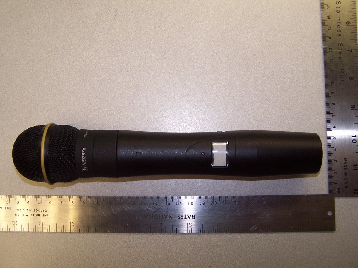
Click to zoom
Application Details
- Equipment Class
- TNF - Licensed Non-Broadcast Transmitter Held to Face
- Date of Grant
- Apr 18, 2012
- Application Purpose
- Original Equipment
- Date of Application
- Apr 18, 2012
- Equipment Note
- 50 mW Plastic Handheld Transmitter
- Frequency Range
- 512.00000000 - 536.00000000
- Company
- Bosch Security Systems, Inc.
- Country
- United States
Documents & Files
Document Text
Text extracted from the exhibit documents filed with the FCC. Open a document above to read the original.
Users Manual
Page 1 Users Manual Electro-Voice Model REV-PH Handheld Wireless Microphone Transmitter The Electro-Voice (Ev) REV-PH is a Professional Grade Wireless Handheld Transmitter operating in the UHF frequency range. The REV-PH combines frequency agility and ease of use like no other. The transmitter operates within a 24 MHz wide segment in 25 KHz steps. The high quality audio circuitry and advanced Radio Frequency (RF) signal processing offer broadcast quality signal-to-noise and audio clarity. The typical line-of- sight distances for the system may be up to 300 feet. System features include: Durable Painted Molded Handle. Permanent Flash Memory for frequency/setting storage. On-Loc prevents accidental power off (when set). LCD Display for ease of viewing. Internal Half Wave Dipole Antenna. Page 2 REV-PH Controls and Connections: 1. Main Display – LCD. 2. Red low battery LED indicator 3. Power On/Off Switch 4. SET Control Button 5. Channel / Frequency Up Switch 6. Channel / Frequency Down Switch 7. Microphone Element 8. 9V Battery Compartment 9. Battery Cover – Screw Type Page 3 Quick set-up: 1. With the Power Switch on the transmitter OFF, install fresh batteries into the transmitter. 2. To prevent feedback or unintentional noise, mute the audio mixer/amplifier or other device during set-up adjustments. Place the transmitter Power Switch to the ON position. 3. The operating screen (display) light will come on momentarily. The display will show the current frequency group and channel. Note: Anytime Power is removed and turned back on, the GP/CH screen will be displayed. The Low Battery light will flash momentarily. 4. If the Group and Channel match the desired receiver group and channel, proceed to Step 11. If not, proceed to Step 5. 5. To select a different GP/CH, press SET one time. The Group will start flashing. Use the up and down arrows to change the group number. Press the SET button to save the Group. 6. After setting the Group, The Channel number will start flashing . Use the up/down arrows to change the Channel number. Press SET and the channel is now saved. 7. There are 18 Groups and up to 16 Channels (preferred groups/channels) stored in memory. If desired, you can create new groups/ channels but you must change to a new frequency to store in that group/channel. 8. In order to select a new frequency, you must have a “users” group /channel selected. Press the SET button. The Group should be flashing. Press the Up arrow until group 19u (user programmable) is found. (group 20u can also be used) Press SET. The Channel should now be flashing. Select a channel with the up/down arrow. Press SET. 9. You are now ready to select a frequency to store in the users group above. Press and hold the set and down arrows at the same time for 3 seconds and release to go to the next screen function. Page 4 10. The next screen displays the operating frequency of the group/channel. If there is no frequency currently stored in the selected users group/channel, a dashed line will be shown. Press SET. The dashed line or frequency will start flashing. Press the up arrow one step at a time to find the desired frequency or hold down the up arrow to scroll through the frequencies quickly. The frequencies can be scrolled either way by the up/down buttons. When the desired frequency is showing, press SET. 11. Press the set and down arrows at the same time then release to go to the next screen function. 12. The next screen shows the battery level in % (percent). Press the set and down arrows at the same time then release to go to the next screen. 13. The next screen shows the audio setting. The display is shown in dB. 0 dB is (maximum volume), -27 dB is (minimum volume). Press the set and down arrows at the same time then release to go to the next screen. Setting the attenuator for the maximum Audio Meter reading on the receiver without peak distortion will produce the best signal to noise ratio. 14. The next screen shows the transmitter RF level (Lo or Hi). Press the Set button if you wish to change the RF level. Press the up button to go to Hi or the down button to go to Lo. Press Set to store. The transmitter RF is normally shipped set to “Lo” for use with multiple frequency systems and the best battery life.“Hi power can be selected for longer distances or to suppress noise or interference. The nominal power in Hi is 50 milliwatts. 15. Press the set and down arrows at the same time then release to go to the next screen function, which will return to the Gp/Ch screen. The display screen will automatically show the Gp/Ch screen when the transmitter is first turned on. 16. When power off is required, simply place the power Off-On switch in the OFF position. The display will then delay slightly to allow the receiver to shut down quietly. Page 5 REV-PH Specifications: RF Frequency range..............................512.0 to 536.0 MHz. RF Channel Step................................. 25 KHz. RF Power......................................... Norm, 5 mW, High, 50 mW (typical). Modulation........................................ FM, 40 KHz Deviation nominal. Audio Frequency Response.....................80-15000 Hz +/- 2 dB. Audio attenuator Range........................ 27 dB. Microphones ( Dynamic)....................... 150 Ohms. Antenna............................................ Internal Half Wave. Power............................................. Two AA Batteries. Battery Life (9 Volt Alkaline)..................8-10 Hours Typical. Approval Information: (English) The Electro-Voice REV-PH Transmitter is Type Accepted under United States Federal Communications Commission CFR 47, Part 74 and Certified to Industry Canada RSS- 123. The device also complies with CRF 47, Part 15 of the FCC Rules and Industry Canada ICES-003 rules. Operation is subject to the following conditions: 1. This device may not cause harmful interference. 2. This device must accept any interference received, including interference that m…
Text truncated - open the document above for the full version.
External Photos
REV-PH Front REV-PH Rear REV-PH Front with Battery Cover Off
ID Label/Location Info
Dynacord | Electro-Voice | RTS | Telex BOSCH and the symbol are registered trademarks of Robert Bosch GmbH, Germany Communications Systems REV-PH Label Artwork: Bosch Security Systems, Inc. 8601 East Cornhusker Highway Lincoln, NE 68507, USA Tel. +1 402 467 5321 x6671 Fax +1 402 467 3279 [email protected] www.boschcommunications.com FCC ID: B5DH226 Model: REV–PH IC: 1321A-REVPHB S.N.: 00XXXX
Internal Photos
REV-PH Internal Overview REV-PH Main PCB Top REV-PH Main PCB Top without Shield and LCD PCB REV-PH Main PCB Bottom REV-PH LCD PCB Top REV-PH LCD PCB Bottom
RF Exposure Info
p1180010_FCC_Part 1.1310_Rev 2.0 Page 1 of 4 Test Report Prepared for: Bosch Security Systems, Inc Model: REV-PH B4 Description: Wireless Microphone Handheld To FCC Part 1.1310 FCC ID: B5DH226 Date of Issue: November 3, 2011 On the behalf of the applicant: Bosch Security Systems, Inc 8601 E. Cornhusker Highway Lincoln, NE 68507 Attention of: Jim Andersen, Principal Electrical Engineer Ph: (402) 467-5321 Fax: (402) 467-3279 E-Mail: [email protected] Prepared by Compliance Testing, LLC 3356 N San Marcos Pl, Suite 107 Chandler, AZ 85225-7176 (866) 311-3268 phone / (480) 926-3598 fax www.compliancetesting.com Project No: p1180010 John Erhard Project Test Engineer This report may not be reproduced, except in full, without written permission from Compliance Testing All results contained herein relate only to the sample tested p1180010_FCC_Part 1.1310_Rev 2.0 Page 2 of 4 Test Report Revision History Revision Date Revised By Reason for Revision 1.0 November 3, 2011 John Erhard Original Document 2.0 January 9, 2012 Amanda Reed Revised Model/Description per Customer Request p1180010_FCC_Part 1.1310_Rev 2.0 Page 3 of 4 ILAC / A2LA Compliance Testing, LLC, has been accredited in accordance with the recognized International Standard ISO/IEC 17025:2005. This accreditation demonstrates technical competence for a defined scope and the operation of a laboratory quality management system (refer joint ISO-ILAC-IAF Communiqué dated January 2009) The tests results contained within this test report all fall within our scope of accreditation, unless noted below Please refer to http://www.compliancetesting.com/labscope.html for current scope of accreditation. Testing Certificate Number: 2152.01 FCC OATS Reg, #933597 IC Reg. #2044A-1 Non-accredited tests contained in this report: N/A p1180010_FCC_Part 1.1310_Rev 2.0 Page 4 of 4 1. Standard Applicable According to 1.1307 (b)(1), systems operating under the provisions of this section shall be operated in a manner that ensure that the public is not exposed to radio frequency energy level in excess of the Commission’s guideline. This is a portable device. 2. Measurement Results Tuned Frequency (MHz) Recorded Measurement (mW) Limit (mW) Result 512 31.7 117.2 Pass 524 31.0 114.5 Pass 536 30.0 111.9 Pass This is a portable device and the max peak output power is 31.7 mW. The peak output power is lower than the low threshold of 60/f GHz = (111.9 mW), for d<2.5 cm general population category. The SAR/MPE measurement is not necessary. END OF TEST REPORT
Test Report
p1180010_FCC_Part 74H_Rev 2.0 Page 1 of 27 Test Report Prepared for: Bosch Security Systems, Inc Model: REV-PH B4 Description: Wireless Microphone Handheld To FCC Part 74H FCC ID: B5DH226 And IC RSS-123 Issue 2 IC ID: 1321A-REVPHB Date of Issue: November 3, 2011 On the behalf of the applicant: Bosch Security Systems, Inc. 8601 E. Cornhusker Highway Lincoln, NE 68507 Attention of: Jim Andersen, Principal Electrical Engineer Ph: (402) 467-5321 Fax: (402) 467-3279 E-Mail: [email protected] Prepared by Compliance Testing, LLC 3356 N San Marcos Pl, Suite 107 Chandler, AZ 85225-7176 (866) 311-3268 phone / (480) 926-3598 fax www.compliancetesting.com Project No: p1180010 John Erhard Project Test Engineer This report may not be reproduced, except in full, without written permission from Compliance Testing All results contained herein relate only to the sample tested p1180010_FCC_Part 74H_Rev 2.0 Page 2 of 27 Test Report Revision History Revision Date Revised By Reason for Revision 1.0 November 3, 2011 John Erhard Original Document 2.0 January 9, 2012 Amanda Reed Revised Model and Description per Customer Request p1180010_FCC_Part 74H_Rev 2.0 Page 3 of 27 Table of Contents Description Page Standard Test Conditions and Engineering Practices 6 Test Result Summary 7 Carrier Output Power (Conducted) 8 Conducted Spurious Emissions 9 Field Strength of Spurious Radiation 13 Emission Masks (Occupied Bandwidth) 16 Audio Low Pass Filter (Voice Input) 20 Audio Frequency Response 21 Modulation Limiting 22 Frequency Stability (Temperature Variation) 24 Frequency Stability (Voltage Variation) 25 Necessary Bandwidth Calculations 26 Test Equipment Utilized 27 p1180010_FCC_Part 74H_Rev 2.0 Page 4 of 27 ILAC / A2LA Compliance Testing, LLC, has been accredited in accordance with the recognized International Standard ISO/IEC 17025:2005. This accreditation demonstrates technical competence for a defined scope and the operation of a laboratory quality management system (refer joint ISO-ILAC-IAF Communiqué dated January 2009) The tests results contained within this test report all fall within our scope of accreditation, unless noted below. Please refer to http://www.compliancetesting.com/labscope.html for current scope of accreditation. Testing Certificate Number: 2152.01 FCC OATS Reg, #933597 IC Reg. #2044A-1 Non-accredited tests contained in this report: N/A p1180010_FCC_Part 74H_Rev 2.0 Page 5 of 27 The Applicant has been cautioned as to the following 15.21: Information to the User The user’s manual or instruction manual for an intentional radiator shall caution the user that changes or modifications not expressly approved by the party responsible for compliance cold void the user’s authority to operate the equipment. 15.27(a): Special Accessories Equipment marketed to a consumer must be capable of complying with the necessary regulations in the configuration in which the equipment is marketed. Where special accessories, such as shielded cables and/or special connectors are required to enable an unintentional or intentional radiator to comply with the emission limits in this part, the equipment must be marketed with, i.e. shipped and sold with, those special accessories. However, in lieu of shipping or packaging the special accessories with the unintentional or intentional radiator, the responsible party may employ other methods of ensuring that the special accessories are provided to the consumer, without an additional charge. Information detailing any alternative method used to supply the special accessories for a grant of equipment authorization or retained in the verification records, as appropriate. The party responsible for the equipment, as detailed in § 2.909 of this chapter, shall ensure that these special accessories are provided with the equipment. The instruction manual for such devices shall include appropriate instructions on the first page of text concerned with the installation of the device that these special accessories must be used with the device. It is the responsibility of the user to use the needed special accessories supplied with the equipment. p1180010_FCC_Part 74H_Rev 2.0 Page 6 of 27 Standard Test Conditions and Engineering Practices Except as noted herein, the following conditions and procedures were observed during the testing. In accordance with ANSI/C63.4-2009, and unless otherwise indicated in the specific measurement results, the ambient temperature of the actual EUT was maintained within the range of 10° to 40°C (50° to 104°F) unless the particular equipment requirements specify testing over a different temperature range. Also, unless otherwise indicated, the humidity levels were in the range of 10% to 90% relative humidity. Environmental Conditions Temperature (º C) Humidity (%) Pressure (mbar) 25.40 22.00 975.70 Accessories: None Cables: None Modifications: None Sub-part 2.1033(c)(14): Test and Measurement Data All tests and measurement data shown were performed in accordance with FCC Rules and Regulations, Volume II, Part 2, Sub-part J, Sections 2.947, 2.1033(c), 2.1041, 2.1046, 2.1047, 2.1079, 2.1051, 2.1053, 2.1055, 2.1057, and the following individual Parts: 74. Measurement results, unless otherwise noted, are worst-case measurements. p1180010_FCC_Part 74H_Rev 2.0 Page 7 of 27 Test Result Summary Specification Test Name Pass, Fail, N/A Comments 2.1046(a) 74.861(e)(1)(i) RSS- 123 (4.2.1.1) Carrier Output Power (Conducted) Pass 2.1051 74.861(e)(6) RSS-123 (5.5.1) Unwanted Emissions (Transmitter Conducted) Pass 2.1053 74.861(e)(6) RSS-123 (5.5.1) Field Strength of Spurious Radiation Pass 74.861(e)(6) RSS-123 (5.5.1) Emission Masks (Occupied Bandwidth) Pass 2.1047(a) Audio Low Pass Filter (Voice Input) Pass 2.1047(a) Audio Frequency Response Pass 2.1047(b) Modulation Limiting Pass 2.1055 74.861(e)(4) RSS-123 (5.4) Frequency Stability (Temperature Variation) Pass 2.1055 RSS-123 (5.4) Frequency Stability (Voltage Variation) Pass 2.202 Necessary Bandwidth Calculation Pass RS…
Text truncated - open the document above for the full version.
Test Setup Photos
Page 1 of 2 Test Setup Photos: Bosch Security Systems, Inc. FCC ID: B5DH226 IC: 1321A-REVPHB Radiated Emissions Radiated Emissions Page 2 of 2 RF Conducted Emissions
Contact Information
Applicant
James R Andersen(Principal Electrical Engineer)
Technical Specifications
| # | Rule Parts | Frequency Range | Power Output | Emission | Tolerance |
|---|---|---|---|---|---|
| 1 | 74 | 512 MHz - 536 MHz | 32.00 mW | 53K6F3E | 0.0050000000 % |
Other Applications from Bosch Security Systems, Inc.

B5DM540
Jun 02, 2020Wireless microphone base station
Equipment Class
TLD - Licensed LPAS Device
B5DM542
Jun 01, 2020Wireless beltpack
Equipment Class
TLD - Licensed LPAS Device
B5DM541
May 27, 2020Wireless beltpack
Equipment Class
TLD - Licensed LPAS Device
B5DM536
Mar 18, 2020Single Receiver UHF Wireless Intercom Beltpack
Equipment Class
TLD - Licensed LPAS Device
B5DM539
Mar 18, 2020Dual Receiver Narrowband UHF Wireless Intercom Beltpack
Equipment Class
TLD - Licensed LPAS Device