B5DM519UHF FM TRANSCEIVER
Bosch Security Systems, Inc.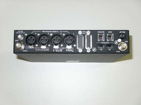
Click to zoom
Application Details
- Equipment Class
- TNB - Licensed Non-Broadcast Station Transmitter
- Date of Grant
- Jul 29, 2004
- Application Purpose
- Original Equipment
- Date of Application
- Jul 29, 2004
- Equipment Note
- UHF FM TRANSCEIVER
- Frequency Range
- 482.00000000 - 607.90000000
- Company
- Bosch Security Systems, Inc.
- Country
- United States
Documents & Files
Document Text
Text extracted from the exhibit documents filed with the FCC. Open a document above to read the original.
Users Manual
Page 1 of 3 Telex Model BTR-1 Base Station Owners / Users Manual (Preliminary Information) General Description: The Telex model BTR-1 base station transceiver is a component of the BTR-1 wireless intercom system. The BTR-1 is intended for use as a rack mountable wireless full duplex intercom radio for use in a professional installation such as television or cinema production. Each BTR-1 base station can be used with one TR-1. The BTR-1 transmits within the 482 to 607.9 MHz range (TV Channels 16-36). It receives in the 614.1 to 746 MHz range (TV Channels 38-59). The BTR-1 transmitter operates on a single frequency within an 18 MHz wide section of the transmit frequency range. The receiver also operates on a single frequency within an 18 MHz wide section of the receiver frequency range. Typical transmitter conducted output power is 50 mW. Operating frequencies can be selected from pre-set groups or the user can select special operating frequencies within the 18 MHz wide allotments. The transmit and receive antennas may be screwed onto the BTR-1 via the TNC Female connectors on the back of the unit. Always make sure the color dot on the back of the base near the antenna jack matches the color of the antenna. Page 2 of 3 1. On/Off Switch – Turns the base station on/off. 2. [MENU] and [SET] buttons – Used to select menus and set options on the LCD. 3. Backlit LCD. 4. [UP] and [DOWN] buttons - Used to select menus and set options on the LCD. 5. Peak Aux Level Light – Will flash red when the auxiliary input level into the base station is too high. 6. Peak Intercom Level Light – Will flash red when the intercom input levels into the base station are too high. 7. Talk Light – Green when the talk button is active. Will turn red when the microphone level into local headset is too high. 8. Talk Button – Press to enable the audio path from the headset. 9. Headphone Volume – Used to adjust the volume level out to a headphone. 10. Microphone Gain – Adjusts the audio gain from the local headset microphone. 11. Local Headset Jack Pin 1 = Ground Pin 2 = Microphone (Hot) Pin 3 = Audio Out + Pin 4 = Audio Out - 12. Relay Contacts – Normally Open. When activated they close. 13. Receive Antenna Connector – TNC Female connector. The color dot near the connector must match the color of the antenna. 14. Auxiliary Connector – RJ-11 connector used to connect auxiliary audio into and out of a base station. 15. CAN bus – RJ-45 connectors used to connect a base station to a CAN type of bus. 16. Matrix Connector – RJ-11 connector used to connect balance 4-W audio into and out of the base station. 17. Intercom Loop Thru – Two DB15 connectors used to loop intercom audio thru a base station. 18. Intercom Jack – XLR intercom jack to allow audio into the base via XLR connectors instead of DB15 connectors. 19. Power Connector – Input power jack which requires 12 to 15 Volts AC or DC at 1000 mA. 20. Transmit Antenna Connector – TNC Female connector. The color dot near the connector must match the color of the antenna. Controls and Connections 1 2 3 4 7 8 6 5 9 10 11 13 12 15 14 16 17 18 19 20 Page 3 of 3 Specifications: General: Input Power..............12 – 15 VDC/VAC @ 1000 mA Antennas..................1/2 wave, TNC male connectors TX / RX...................One transmitter, one receiver, Frequency agile, 25 KHz steps, within 18MHz wide allotments. Frequency Range RX................614.1 – 746 MHz TX................482 – 607.9 MHz (within 18MHz wide allotments) TX / RX Data Rate........................150 kbps Aux In......................................2 Vrms typical Aux Out....................................2 Vrms typical 4-wire In...................................2 Vrms typical 4-wire Out.................................2 Vrms typical Transmitter: RF Power Output.....................50 mW typical (terminated) Modulation type......................GMSK Audio Frequency Response.........100 Hz to 7 kHz Microphone Sensitivity ..............10 mV Receiver: Sensitivity............<0.8uV for 12 dB SINAD Typical Audio Frequency Response....100 Hz to 7 KHz Audio Output (headset).......40 mW, 600 Ohms (1% Distortion)
Cover Letter(s)
Telex Communications, Inc. 8601 E. Cornhusker Hwy Lincoln, NE 68507 402-467-5321 Date: July 27, 2004 To: Federal Communications Commission EQUIPMENT APPROVAL SERVICES P.O. Box 358315 Pittsburgh, PA 15251-5315 To: INDUSTRY CANADA Certification & Engineering Bureau 3701 Carling Avenue, Bldg. 94 P.O. Box 11490, Station “H” Ottawa, Ontario, Canada K2H 8S2 Per: 47 CFR 0.457 and 0.459 Re: FCC ID: B5DM519 Model:BTR-1 Pursuant to Sections 0.457 (d) (1) (ii) and 0.459 of the Commission’s Rules, the applicant hereby requests confidential treatment of some of the information accompanying this application as listed below, i.e. Block Diagram, Schematics, Parts Lists, List of Active Devices, Tune-up Procedures (alignment procedure), Operational Description (theory of operation). These materials contain trade secrets and proprietary information not customarily released to the public and the public disclosure of these matters might be harmful to the applicant and provide unjustified benefits to its competitors. The applicant understands that pursuant to Rule 0.457 (d) (1) (ii) disclosure of this application and all accompanying documentation will not be made before the date of the grant of this application. Sincerely, Charles E. Conner Senior Project Engineer Telex Communications, Inc.
ID Label/Location Info
APPLICATIONS CHG. NO. NEXT ASSY.USED ON LTR REVISIONS DESCRIPTIONDATE APPD ARELEASE DATE DR BY CHK BY APPD. PROD. TOLERANCES UNLESS OTHERWISE SPECIFIED FRACTION DECIMAL ANGLE This drawing, written description or specifi- cation represents a proprietary product of Telex, Lincoln, NE, and shall not be released, disclosed, used nor duplicated without the written permission of TELEX SIZE CODE IDENT DWG. NO. S TELEX TELEX COMMUNICATIONS, INC. Lincoln, Nebraska U.S.A. SCALESHEET TITLE UNLESS OTHERWISE SPECIFIED DIMENSIONS ARE IN INCHES. 57010 NONE 1of1 FCC ID: B5DM519 IC: 1321A-BTR1 S.N.:XXXX 2” 1.25” BTR-1 SERIAL NUMBER LABEL 803956 803956 70-000015 07/20/04 JRC 07/20/04 JTN NH JRC 07/20/04 BTR-1 This device complies with part 15 of the FCC Rules. Operation is subject to the conditions that this device does not cause harmful interference.
Test Report
FCC ID: B5DM519 Environmental Assessment for Mobiles/Fixed Base Station for FCC ID: B5DM519 Model:BTR-1 to Federal Communications Commission 47 CFR 1.1310 (MPE) Radiofrequency Radiation Exposure Limits Date Of Report: July 26, 2004 On the Behalf of the Applicant: Telex Communications, Inc. At the Request of: P.O. 302560 Telex Communications, Inc. 8601 E. Cornhusker Highway P.O. Box 5579 Lincoln, NE 68505-5579 Attention of: Charles E. Conner, Project Engineer (402) 467-5321; FAX: -3279 E-mail: [email protected] Jim Andersen Email: [email protected] Supervised By: David E. Lee, Lab Manager MFA p0470003, d0470054 FCC ID: B5DM519 Table of Contents Rule Description Page . Test Report 1 . Identification of the Equipment Under Test 2 . Standard Test Conditions and Engineering Practices 4 1.1310 Environmental Assessment 5 MFA p0470003, d0470054 FCC ID: B5DM519 Page Number 1 of 5. Required information per ISO/IEC Guide 25-1990, paragraph 13.2: a) Test Report (Supplemental) b) Laboratory: (FCC: 31040/SIT) (Canada: IC 2044) M. Flom Associates, Inc. 3356 N. San Marcos Place, Suite 107 Chandler, AZ 85225 c) Report Number: d0470054 d) Client: Telex Communications, Inc. 8601 E. Cornhusker Highway P.O. Box 5579 Lincoln, NE 68505-5579 e) Identification: BTR-1 FCC ID: B5DM519 Description: UHF FM Transceiver f) EUT Condition: Not required unless specified in individual tests. g) Report Date: July 26, 2004 EUT Received: h, j, k): As indicated in individual tests. i) Sampling method: No sampling procedure used. l) Uncertainty: In accordance with MFA internal quality manual. n) Results: The results presented in this report relate only to the item tested. m) Supervised by: David E. Lee, Compliance Test Manager o) Reproduction: This report must not be reproduced, except in full, without written permission from this laboratory. MFA p0470003, d0470054 FCC ID: B5DM519 Page Number 2 of 5. Identification of the Equipment Under Test (EUT) Name and Address of Applicant: Telex Communications, Inc. 8601 E. Cornhusker Highway P.O. Box 5579 Lincoln, NE 68505-5579 Manufacturer: Telex Communications, Inc. FCC ID: B5DM519 Model Number: BTR-1 Description: UHF FM Transceiver Type of Emission: 200KF1E Frequency Range, MHz: 482 to 607.9 Power Rating, Watts: 0.050 Switchable X Variable N/A Modulation: AMPS TDMA CDMA X OTHER Antenna: Helical Monopole X Whip Other Note: For RF Safety test antenna gain taken at the upper range of expected gain (i.e. 0 dBd) and RF Power set to highest nominal power across all channels. MFA p0470003, d0470054 FCC ID: B5DM519 Page Number 3 of 5. A2LA “A2LA has accredited M. Flom Associates, Inc. Chandler, AZ for technical competence in the field of Electrical Testing. The accreditation covers the specific tests and types of tests listed on the agreed scope of accreditation. This laboratory meets the requirements of ISO/IEC 17025 – 1999 ‘General Requirements for the Competence of Testing and Calibration Laboratories’ and any additional program requirements in the identified field of testing.” Certificate Number: 2152-01 NIST I am pleased to inform you that your laboratory has been validated by the Chinese Taipei Bureau of Standards, Metrology and Inspection (BSMI) under the Asia Pacific Economic Cooperation Mutual Recognition Agreement (APEC MRA). Your laboratory is now formally designated to act as a Conformity Assessment Body (CAB) under Appendix B, Phase I Procedures, of the APEC MRA between the American Institute in Taiwan (AIT) and the Taipei Economic and Cultural Representative Office (TECRO) in the United States, covering equipment subject to Electro- Magnetic Compatibility (EMC) requirements. The names of all validated and nominated laboratories will be posted on the NIST website at http://ts.nist.gov/mra under the ‘Asia’ category.” BSMI Number: SL2-IN-E-041R MFA p0470003, d0470054 FCC ID: B5DM519 Page Number 4 of 5. Standard Test Conditions and Engineering Practices Except as noted herein, the following conditions and procedures were observed during the testing: In accordance with ANSI C63.4-1992/2000, section 6.1.9, and unless otherwise indicated in the specific measurement results, the ambient temperature of the actual EUT was maintained within the range of 10° to 40°C (50° to 104 °F) unless the particular equipment requirements specify testing over a different temperature range. Also, unless otherwise indicated, the humidity levels were in the range of 10% to 90% relative humidity. Prior to testing, the EUT was tuned up in accordance with the manufacturer's alignment procedures. All external gain controls were maintained at the position of maximum and/or optimum gain throughout the testing. Measurement results, unless otherwise noted, are worst-case measurements. MFA p0470003, d0470054 FCC ID: B5DM519 Page Number 5 of 5. Name of Test: Environmental Assessment Specification: FCC: 47 CFR 1.1310 MPE Calculated Frequency, MHZ 482 Limit f/1500 = 0.321 mW/cm² Minimum Safe Distance = [0.050/(12.56 x 3.21)]1/2 = 0.0352 m = 3.52 cm Supervised By: David E. Lee, Compliance Test Manager MFA p0470003, d0470054 FCC ID: B5DM519 (The following will be placed in the Instruction Manual) Mandatory Safety Instructions to Installers & Users Use only manufacturer or dealer supplied antenna. Antenna Minimum Safe Distance: 3.56cm. Antenna Gain: zero dBd referenced to a dipole. The Federal Communications Commission has adopted a safety standard for human exposure to RF (Radio Frequency) energy which is below the OSHA (Occupational Safety and Health Act) limits. Antenna Mounting: The antenna supplied by the manufacturer or radio dealer must not be mounted at a location such that during radio transmission, any person or persons can come closer than the above indicated minimum safe distance to the antenna i.e. 3.56cm . To comply with current FCC RF Exposure limits, the antenna must be installed at or exceeding the minimum safe distance shown above, and in accordance with the requirements of the antenna manu…
Text truncated - open the document above for the full version.
Contact Information
Applicant
James R Andersen(Principal Electrical Engineer)
Test Firm
Compliance Testing, LLCMichael Schafer
Technical Specifications
| # | Rule Parts | Frequency Range | Power Output | Emission | Tolerance |
|---|---|---|---|---|---|
| 1 | 74 | 482 MHz - 607.9 MHz | 50.00 mW | 200KF1E | 50.0000000000 ppm |
Other Applications from Bosch Security Systems, Inc.

B5DM540
Jun 02, 2020Wireless microphone base station
Equipment Class
TLD - Licensed LPAS Device
B5DM542
Jun 01, 2020Wireless beltpack
Equipment Class
TLD - Licensed LPAS Device
B5DM541
May 27, 2020Wireless beltpack
Equipment Class
TLD - Licensed LPAS Device
B5DM536
Mar 18, 2020Single Receiver UHF Wireless Intercom Beltpack
Equipment Class
TLD - Licensed LPAS Device
B5DM539
Mar 18, 2020Dual Receiver Narrowband UHF Wireless Intercom Beltpack
Equipment Class
TLD - Licensed LPAS Device