B5DM520BELTPACK TRANSCEIVER
Bosch Security Systems, Inc.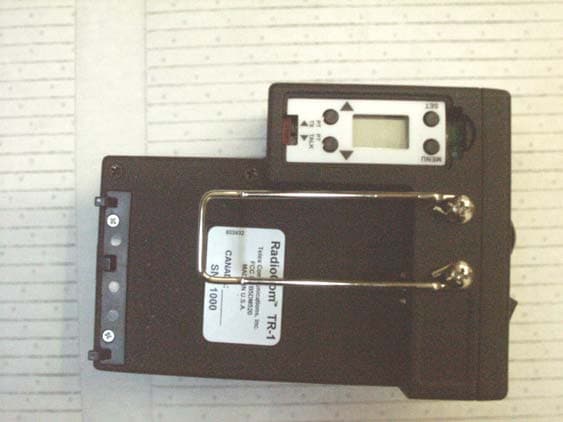
Click to zoom
Application Details
- Equipment Class
- TNT - Licensed Non-Broadcast Transmitter Worn on Body
- Date of Grant
- Jul 19, 2004
- Application Purpose
- Original Equipment
- Date of Application
- Jul 19, 2004
- Equipment Note
- BELTPACK TRANSCEIVER
- Frequency Range
- 614.00000000 - 746.00000000
- Company
- Bosch Security Systems, Inc.
- Country
- United States
Documents & Files
Document Text
Text extracted from the exhibit documents filed with the FCC. Open a document above to read the original.
Users Manual
Telex Model TR-1 Beltpack From the LCD display and buttons the following menus may be obtained: • Group and Channel • Transmit Frequency • Receive Frequency • Battery Life • Microphone Gain The on/off/volume control, talk button, talk light, low battery indicator, microphone level indicator, A/B audio rocker switch and lights, are located on the top panel. Owners / Users Manual (Preliminary Information) The C audio button is located on the front panel. General Description: Transmit and receive antennas are attached to the TR- 1. Either or both unscrew for field replacement but are not coaxial connectors. The Telex model TR-1 beltpack transceiver is a component of the BTR-1 wireless intercom system. The TR-1 is intended for use as a belt worn wireless full duplex mobile intercom radio for use in a professional installation such as television or cinema production. The TR-1 beltpack can be powered by AA Alkaline or a Nickel-Metal Hydride Battery pack. Each BTR-1 base station can be used with one TR-1. The TR-1 transmits within the 614 to 746 MHz range (TV Channels 38-59). It receives in the 482 to 608 MHz range (TV Channels 16-36). The TR-1 transmitter operates on a single frequency within an 18 MHz wide section of the transmit frequency range. The receiver also operates on a single frequency within an 18 MHz wide section of the receiver frequency range. Typical transmitter conducted output Power is 50 mW. The TR-1 transmit power can be set to automatically reduced when the unit is close-in to the base station to aid in intermodulation reduction and unnecessary transmit power. Operating frequencies can be selected from pre-set groups or the user can select special operating frequencies within the 18 MHz wide allotments. The LCD display and buttons plus the talk function switch, is located on the back panel. Page 1 of 1 Controls and Connections 1. On/Off & Volume Control – Turns the beltpack power on and controls headset volume. 11 10 9 5 6 8 7 4 5 3 2 1 15 14 13 12 9. [MENU] and [SET] buttons – Used to select menus and set options on the LCD. 2. BAT/O.M. Light – Battery - Light flashes once on power up = Battery OK 10. LCD display. Light on continuously = Battery Low Light does not flash or come on = Battery Dead 11. [UP] and [DOWN] buttons - Used to select menus and set options on the LCD. Microphone Lvl: Light flashes on loudest speech = Gain OK Light flashes on all speech = Gain too High 12. Push-to-Talk/Push-to-Transmit Switch – Light never flashes on loudest speech = Gain too Low PT TALK (Push-to-Talk) – The transmitter is always on. No audio is sent unless the talk button is active. Recommended position. 3. Talk Light – Light on if talk button active. 4. Talk Button – Press to enable the audio path from the headset. PT TX (Push-to-Transmit) – The transmitter and audio path are off except when the talk button is active. Software Selectable modes: Push-to-Talk Push-to-Latch 13. Headset Connector – XLR Plug for Telex units, XLR Receptacle for RTS units. 5. A and B Lights – “A” light is on if Selection Switch in A position. “B” light is on if Selection switch in B position. 14. Battery Latch – Press down to enable the battery pack to be released. While the latch is held down, slide the battery pack about 1/8 inch back, toward the latch, until it stops, then lift out. 6. Selection Switch – Switches between base station presets A or B. 7. “C” Pushbutton – Press to enable the base station “C” presets. Software Selectable modes: Push-to-Talk 15. Receive and Transmit Antennas – The antennas are screw type, ¼ wave, replaceable antennas. The color dot on the screw end of the antenna must match color dot on antenna receptacle. Push-to-Latch Off 8. “C” Button Light – “C” light is on if “C” pushbutton active. Page 2 of 2 Page 3 of 3 Specifications: General: Input Power..............9.0 VDC Alkaline or NiMH. Antennas.......................................Attached TX / RX....................One TX, one RX Frequency agile, 25 KHz steps, within 18MHz wide allotments. Frequency Range TX................614 – 746 MHz RX................482 – 608 MHz (within 18MHz wide allotments) TX / RX Data Rate........................150 kbps Transmitter: RF Power Output.....................50 mW typical (terminated) Modulation type......................GMSK Audio Frequency Response.........100 Hz to 7 kHz Microphone Sensitivity ..............7.75 mV Receiver: Sensitivity............<0.8uV for 12 dB SINAD Typical Audio Frequency Response....100 Hz to 7 KHz Audio Output (headset).......40 mW, 600 Ohms (1% Distortion)
Cover Letter(s)
Telex Communications, Inc. 8601 E. Cornhusker Hwy Lincoln, NE 68507 402-467-5321 Date: July 15, 2004 To: Federal Communications Commission EQUIPMENT APPROVAL SERVICES P.O. Box 358315 Pittsburgh, PA 15251-5315 To: INDUSTRY CANADA Certification & Engineering Bureau 3701 Carling Avenue, Bldg. 94 P.O. Box 11490, Station “H” Ottawa, Ontario, Canada K2H 8S2 Per: 47 CFR 0.457 and 0.459 Re: FCC ID: B5DM520 Model: TR-1 Pursuant to Sections 0.457 (d) (1) (ii) and 0.459 of the Commission’s Rules, the applicant hereby requests confidential treatment of some of the information accompanying this application as listed below, i.e. Block Diagram, Schematics, Parts Lists, List of Active Devices, Tune-up Procedures (alignment procedure), Operational Description (theory of operation). These materials contain trade secrets and proprietary information not customarily released to the public and the public disclosure of these matters might be harmful to the applicant and provide unjustified benefits to its competitors. The applicant understands that pursuant to Rule 0.457 (d) (1) (ii) disclosure of this application and all accompanying documentation will not be made before the date of the grant of this application. Sincerely, Charles E. Conner Senior Project Engineer Telex Communications, Inc.
Contact Information
Applicant
James R Andersen(Principal Electrical Engineer)
Test Firm
Compliance Testing, LLCMichael Schafer
Technical Specifications
| # | Rule Parts | Frequency Range | Power Output | Emission | Tolerance |
|---|---|---|---|---|---|
| 1 | 74 | 614 MHz - 746 MHz | 50.00 mW | 173KF1E | 50.0000000000 ppm |
Other Applications from Bosch Security Systems, Inc.

B5DM540
Jun 02, 2020Wireless microphone base station
Equipment Class
TLD - Licensed LPAS Device
B5DM542
Jun 01, 2020Wireless beltpack
Equipment Class
TLD - Licensed LPAS Device
B5DM541
May 27, 2020Wireless beltpack
Equipment Class
TLD - Licensed LPAS Device
B5DM536
Mar 18, 2020Single Receiver UHF Wireless Intercom Beltpack
Equipment Class
TLD - Licensed LPAS Device
B5DM539
Mar 18, 2020Dual Receiver Narrowband UHF Wireless Intercom Beltpack
Equipment Class
TLD - Licensed LPAS Device