B5DM521AUDITORY ASSISTANCE TRANSMITTER
Bosch Security Systems, Inc.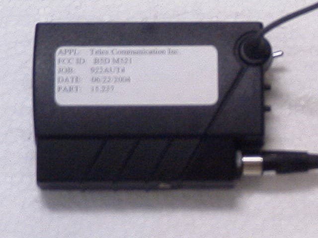
Click to zoom
Application Details
- Equipment Class
- GAT - Part 15 Auditory Assistance Device (Transmitter)
- Date of Grant
- Jul 21, 2004
- Application Purpose
- Original Equipment
- Date of Application
- Jul 21, 2004
- Equipment Note
- AUDITORY ASSISTANCE TRANSMITTER
- Frequency Range
- 72.10000000 - 75.90000000
- Company
- Bosch Security Systems, Inc.
- Country
- United States
Documents & Files
Document Text
Text extracted from the exhibit documents filed with the FCC. Open a document above to read the original.
Users Manual
Owners Manual/Operating Instructions Telex Model PST-170 Auditory Assistance Transmitter Carefully inspect your Auditory Assistance Transmitter. If there is any damage or shortages, please refer to the “Warranty Information Section”. Set-up Instructions: Power: Power is provided by 2 “AA” size batteries. Alkaline batteries provide the best battery life. Nickel Cadmium or Nickel Metal Hydride rechargeable batteries can be used also but with shorter battery life. Install batteries as shown in the illustrations but do not apply power to the transmitter at this time. CAUTION: Do not attempt to recharge Alkaline Batteries as this may result in personal injury. Charge Pins are provided on the bottom of the unit that fit TELEX drop in chargers. Frequency/Channel Considerations: As with any radio device, interference can occur at any time. The frequencies offered are shared with other legitimate users. Check the frequency/channel with the matching receiver to see if any interference is present. If interference is present, choose a different channel. The severity of interference varies with location and distance to the interfering station. If the interference is weak on all channels, this is probably acceptable since your transmitter will cover the interference and is unlikely to interfere with other users. Multiple Channel Systems require other considerations but each channel should be checked as above. Transmitter Location: Select a clear, unobstructed path between the transmitter and the receiver if possible, for best performance. The transmitter should not be used between objects such as metallic building structures and file cabinets as this can cause short distance performance and reflections that could cause fading of the signal. Place the transmitter on the users belt or pocket, preferably with the antenna facing the receiver. Do not coil the atenna and put it in a pocket. This will severely reduce the operating distance. Transmitter Operation: Now that you have checked all of the channels you intend to use, apply power to the transmitter by moving the Toggle Switch on top of the transmitter towards the Function Display. The display will light up for approximately 8-10 seconds allowing better viewing in low light situations. Pressing either of the Function Buttons will also cause the screen to light up for 8-10 seconds. Use the function push buttons to select any of the items listed in the Function Instructions below. Antenna: The transmitter uses a flexible wire “trailing” antenna that is permanently attached to comply with FCC Part 15 Rules. Do not cut or lengthen the antenna . This is a tuned antenna and modification will shorten the operating range. TELEX PST-170 Transmitter, Continued Page 2 Operating Instructions: Battery Power is applied to the transmitter with the toggle switch on the top of the transmitter. The display on the top of the transmitter will then show the Operating Channel, a small Lock icon (if Lock is ON) and E.D.R. The two pushbuttons above the display are used to “program” the remainder of the transmitter functions, as shown below. The “Set” button is on the left and the “up” button is on the right. Pressing the Set button one time will cause the item on the display to “blink” or “flash”. Pressing the Set button again will “Set” or store the item in memory. When the displayed item is flashing, pressing the Up button selects the next item. Once the desired item is selected, press Set again to store the item in memory. The Lock function must be disabled to make any changes. Operation Function/Result Press and hold the Set and Up buttons for 5-10 seconds until the Lock icon either comes on the display or goes off the display as desired. If you hold both buttons too long, the Lock will come back on or go off. Press set Channel (“blinks”) flashes. Press up Channel increments. Stop on desired channel. If the channel is missed, continue pressing the Up button until the desired channel appears again. Press set flash stops, Channel is set in memory. Press set Mic Gain setting flashes. Press up Audio Level increases at 6 dB per step. (see E.D.R. and AUX audio section) If the desired setting is missed, continue pressing up until desired level appears again. Press set flash stops, Level is set in memory. Terminates edit mode. Special Function Programming : E.D.R. : If E.D.R. does not already show on the display and Enhanced Audio Performance is desired, Switch the toggle switch off for a few seconds. Press and hold the Set button, switch the toggle switch back ON. The E.D.R. icon will be ON if E.D.R. is enabled. To disable E.D.R., Hold the Set button down when the power is applied. Low Battery: The Treble Clef icon flashes when the battery voltage goes below 2.0 Volts. TELEX PST-170 Transmitter, Continued Page 3 Audio Input: There are 2 audio input jacks on the transmitter. One is the normally used microphone input. This input is located on the transmitter top panel “step”. A microphone is supplied with the transmitter but other types can be used as well. Place the microphone element about 8 to 10 inches below the mouth of the user. Adjust the gain mentioned above to adjust the transmitted volume. Excessive input levels may sound unnatural and the Treble Clef symbol will come on, indicating “overload”. Adjust the microphone volume before using the Aux input. The second audio input, the Auxilliary input jack is located on the side of the transmitter case. The input jack is a 1/8 inch stereo/mono jack designed to allow audio devices such as teachers aids or tape recorders to be used. Typical input level is 100 mV RMS maximum for normal modulation. Input exceeding this level will cause the audio to “limit” which may also sound unnatural. Input “overload” will be indicated by the Treble Clef Symbol coming on (flashing). Reduce the input level in if this should happen, with the input device’s control . Turn the program material on (tape recorder, PA, etc. or use the microphone) Adj…
Text truncated - open the document above for the full version.
Block Diagram
3V REG UP STEP 3.3V 5V 3.3V LCD 32.768kHz OSCILLATOR PRE- EMPHASIS MODULATION LIMITER COMPRESSOR AMP MIC IN PST-170 BLOCK DIAGRAM MICROPROCESSOR PLL OSCAMP AMPAMP 72.1 TO 75.9 MHZ 10MHz
Cover Letter(s)
Rev. 1/1/03 Telex Communications Inc. 8601 E. Cornhusker Highway Lincoln, NE 68507-9702 To: Federal Communications Commission Authorization and Evaluation Division Confidentiality Request regarding application for certification of FCC ID: B5DM521 Pursuant to Sections 0.457 and 0.459 of the Commission’s Rules, we hereby request confidential treatment of information accompanying this application as outlined below: Schematics Block diagram Operational description Parts List Tune-up procedure. The above materials contain trade secrets and proprietary information not customarily released to the public. The public disclosure of these materials may be harmful to the applicant and provide unjustified benefits to its competitors. The applicant understands that pursuant to Section 0.457 of the Rules, disclosure of this application and all accompanying documentation will not be made before the date of the Grant for this application. Sincerely, Charles E. Conner Project Engineer Telex Communications Inc.
ID Label/Location Info
FCC LABEL LOCATION
ID Label/Location Info
APPLICATIONS CHG.NO. NEXTASSY.USEDON LTR REVISIONS DESCRIPTION DATE APPD ARelease SPEC.CONTROLDWG. DATE DRBY CHKBY APPD. PROD. TOLERANCES UNLESSOTHERWISE SPECIFIED FRACTION DECIMAL ANGLE Thisdrawing,writtendescriptionorspecifi- cationrepresentsaproprietaryproductof Telex,Lincoln,NE,andshallnotbe released,disclosed,usednorduplicated withoutthewrittenpermissionofTELEX SIZECODEIDENT DWG.NO. S TELEX TELEXCOMMUNICATIONS,INC. Lincoln,NebraskaU.S.A. SCALESHEET TITLE UNLESSOTHERWISE SPECIFIEDDIMENSIONS AREININCHES. 57010 570413000 PST-170 S.N./FCCLABEL NONE 04-29-04 7.LABELSTOBEKISS-CUTONSTRIPSORROLLS. 6.S/NTOBESCREENEDINBYSUPPLIER.NUMERALSTOSTARTAT1,000. ANDWILLBEINSEQUENCEASPERTELEXSUPPLIEDINFORMATION. NUMERALSTOBE1/16”TALL. 5.COLOR:WHITEBACKGROUNDWITHBLACKLETTERING. 4.ARTWORKISREV.A 3.TELEXLINCOLNTOSUPPLYARTWORK. 2.ADHESIVE:PRESSURESENSITIVEPERMANENTWITHPAPERRELEASELINER. 1.MATERIAL:.004WHITEVINYLW/.001CLEARPOLYESTERLAMINATION NOTES: JTN 04-29-04JRC NH 21/4”/23/4” MadeinU.S.A. .82 1.95 .03R PST-170 Thisdevicecomplieswithpart15oftheFCCrules.Operationis TELEXCOMM.INC.PST-170 S.N.:XXXXXX 1/4”-1/2” subjecttothefollowingconditions:(1)Thisdevicemaynotcause harmfulinterference,and(2)thisdevicemustacceptanyinterference receivedincludinginterferencethatmaycauseundesiredoperation. FCCID:B5DM521 INCREASING SERIAL Nos. 5-000007 JRC04-29-04 MadeinU.S.A. Thisdevicecomplieswithpart15oftheFCCrules.Operationis TELEXCOMM.INC.PST-170 S.N.:XXXXXX subjecttothefollowingconditions:(1)Thisdevicemaynotcause harmfulinterference,and(2)thisdevicemustacceptanyinterference receivedincludinginterferencethatmaycauseundesiredoperation. FCCID:B5DM521 MadeinU.S.A. Thisdevicecomplieswithpart15oftheFCCrules.Operationis TELEXCOMM.INC.PST-170 S.N.:XXXXXX subjecttothefollowingconditions:(1)Thisdevicemaynotcause harmfulinterference,and(2)thisdevicemustacceptanyinterference receivedincludinginterferencethatmaycauseundesiredoperation. FCCID:B5DM521 Thisdevicecomplieswithpart15oftheFCCrules.Operationis TELEXCOMM.INC.PST-170
Operational Description
PST-170 THEORY OF OPERATION 1. Audio section. Audio from J1 is fed directly to U1. Audio from J2 is attenuated 22dB and fed to U1. U2 allows the gain of U1 to be software controlled. This is user adjusted from 0dB to 42dB in 6dB steps. C6, R9 and R10 provide pre-emphasis. U3C is a compressor that can be switched on or off via U4. When on it has a 2:1 compression ratio and when off it is 1:1. U3A, U3B, Q2 and associated components form a modulation limiter. This limiter will function regardless of what state the compressor is in. U3D is a low pass filter. 2. PLL and Transmit Stages. Q3 and associated components form a voltage controlled oscillator operating between 72.1MHz and 75.9MHz. The output of the oscillator is buffered by Q4 and fed to PLL U5. U103 provides the serial data to U5 to program the desired frequency of operation. The 10MHz reference is generated by Q102. Varactor D2 is driven by the phase detector output and closes the loop. Audio is fed to a separate varactor, D1. The deviation is set by VR1. Q6 is an amplifier stage and Q8 is the power output stage. Q5 and Q7 are used to switch off Q6 until lock is achieved.
Schematics
770907rev2.sch-1 - Thu Jun 03 12:07:46 2004 600766_4.sch-1 - Fri May 21 10:14:08 2004
Test Report
TIMCO ENGINEERING INC. 849 NW State Road 45 Newberry, Florida 32669 http://www.timcoengr.com 888.472.2424 F 352.472.2030 email: [email protected] APPLICANT: TELEX COMMUNICATIONS INC. FCC ID: B5DM521 REPORT #: T\TELEX\922AUT4\922AUT4TestReport.doc COVER SHEET Test Report Product Name: AUDITORY ASSISTANCE TRANSMITTER FCC ID: B5DM521 Applicant: TELEX COMMUNICATION INC. 8601 E. CORNHUSKER HIGHWAY PO BOX 5579 LINCOLN, NEBRASKA 68505-5579 Date Receipt: JUNE 21, 2004 Date Tested: JUNE 30, 2004 TIMCO ENGINEERING INC. 849 NW State Road 45 Newberry, Florida 32669 http://www.timcoengr.com 888.472.2424 F 352.472.2030 email: [email protected] APPLICANT: TELEX COMMUNICATIONS INC. FCC ID: B5DM521 REPORT #: T\TELEX\922AUT4\922AUT4TestReport.doc TABLE OF CONTENTS APPLICANT: TELEX COMMUNICATIONS INC. FCC ID: B5DM521 TABLE OF CONTENTS TEST REPORT CONTAINING: PAGE 1.............TEST EQUIPMENT LIST PAGE 2.............TEST PROCEDURE PAGE 3-5...........RADIATION INTERFERENCE TEST DATA PAGE 6.............OCCUPIED BANDWIDTH PAGE 7.............OCCUPIED BANDWIDTH PLOT EXHIBITS CONTAINING: REQUEST FOR CONFIDENTIALITY LETTER BLOCK DIAGRAM SCHEMATIC USERS MANUAL LABEL SAMPLE LABEL LOCATION EXTERNAL PHOTOGRAPHS INTERNAL PHOTOGRAPHS OPERATIONAL DESCRIPTION TEST SET UP PHOTOGRAPHS TIMCO ENGINEERING INC. 849 NW State Road 45 Newberry, Florida 32669 http://www.timcoengr.com 888.472.2424 F 352.472.2030 email: [email protected] APPLICANT: TELEX COMMUNICATIONS INC. FCC ID: B5DM521 REPORT #: T\TELEX\922AUT4\922AUT4TestReport.doc Page 1 of 7 EMC Equipment List Device Manufacturer Model Serial Number Cal/Char Date Due Date 3/10-Meter OATS TEI N/A N/A Listed 3/27/04 3/26/07 3-Meter OATS TEI N/A N/A Listed 1/13/03 1/12/06 Biconnical Antenna Eaton 94455-1 1057 CAL 3/18/03 3/18/05 Biconnical Antenna Eaton 94455-1 1096 CAL 10/1/01 10/1/03 Biconnical Antenna Electro- Metrics BIA-25 1171 CAL 4/26/01 4/26/03 Blue Tower Quasi-Peak Adapter HP 85650A 2811A01279 CAL 4/15/03 4/15/05 Blue Tower RF Preselector HP 85685A 2620A00294 CAL 4/27/04 4/27/06 Blue Tower Spectrum Analyzer HP 8568B 2928A04729 2848A18049 CAL 4/15/03 4/15/05 LISN Electro- Metrics ANS-25/2 2604 CAL 10/9/01 10/9/03 LISN Electro- Metrics EM-7820 2682 CAL 3/12/03 3/12/05 Log- Periodic Antenna Eaton 96005 1243 CAL 5/8/03 5/8/05 TIMCO ENGINEERING INC. 849 NW State Road 45 Newberry, Florida 32669 http://www.timcoengr.com 888.472.2424 F 352.472.2030 email: [email protected] APPLICANT: TELEX COMMUNICATIONS INC. FCC ID: B5DM521 REPORT #: T\TELEX\922AUT4\922AUT4TestReport.doc Page 2 of 7 TEST PROCEDURES GENERAL: This report shall NOT be reproduced except in full without the written approval of TIMCO ENGINEERING, INC. RADIATION INTERFERENCE: The test procedure used was ANSI STANDARD C63.4-1992 using a HEWLETT PACKARD spectrum analyzer with a pre-selector. In the frequency range 10 kHz to 30 MHz the RBW was 10 kHz and from 30-1000 MHz the RBW of the spectrum analyzer was 100 kHz with an appropriate sweep speed. The analyzer was calibrated in dB above a microvolt at the output of the antenna. The resolution bandwidth was 100 kHz and the video bandwidth was 300 kHz. The ambient temperature of the UUT was &tempr& with a humidity of &humr&. FORMULA OF CONVERSION FACTORS: The Field Strength at 3m was established by adding the meter reading of the spectrum analyzer (which is set to read in units of dBuV) to the antenna correction factor supplied by the antenna manufacturer. The antenna correction factors are stated in terms of dB. The gain of the Preselector was accounted for in the Spectrum Analyzer Meter Reading. Example: Freq (MHz) METER READING + ACF = FS 33 20 dBuV + 10.36 dB = 30.36 dBuV/m @ 3m ANSI C63.4-1992 Section 8.2.1 MEASUREMENT PROCEDURES: The EUT was placed on a non-conducting table 80 cm above the ground plane with the EUT located in the center of the table. With the antenna vertical a preliminary scan was done at 1 meters distance, the EUT was moved to a 3.0-meter distance and the antenna height varied and also placed in a horizontal position. The frequency was scanned from 9.0 kHz to 1.0 GHz. When an emission was found, the table was rotated to produce the maximum signal strength. The EUT was measured in three (3) orthogonal planes. The unit was measured at TIMCO ENGINEERING, INC. located at 849 N.W. State Road 45 Newberry, Florida 32669. TIMCO ENGINEERING INC. 849 NW State Road 45 Newberry, Florida 32669 http://www.timcoengr.com 888.472.2424 F 352.472.2030 email: [email protected] APPLICANT: TELEX COMMUNICATIONS INC. FCC ID: B5DM521 REPORT #: T\TELEX\922AUT4\922AUT4TestReport.doc Page 3 of 7 APPLICANT: TELEX COMMUNICATIONS INC. FCC ID: B5DM522 NAME OF TEST: RADIATION INTERFERENCE RULES PART NO. 15.237 REQUIREMENTS: CARRIER FREQUENCY WILL NOT EXCEEDS 98.0 dBuV/m AT 3M. OUT-OF-BAND EMISSIONS, OTHER THAN EMISSIONS IN THE RESTRICTED BAND SHALL NOT EXCEED 63.5 dBuV/m AT 3M. TEST DATA: Emission Frequency MHz Meter Reading dBuV Ant. Polarity Coax Loss dB Correction Factor dB Field Strength dBuV/m Margin dB 72.30 53.5 V 0.80 5.89 60.19 37.81 72.30 62.9 H 0.80 6.30 70.00 28.00 144.60 9.5 H 1.71 15.94 27.15 36.35 144.60 13.4 V 1.71 16.64 31.75 31.75 216.90 11.5 V 2.22 11.36 25.08 38.42 216.90 17.9 H 2.22 12.12 32.24 31.26 289.20 10.4 V 2.72 13.78 26.90 36.60 289.20 14.9 H 2.72 14.49 32.11 31.39 361.50 9.7 V 2.91 15.03 27.64 35.86 361.50 11.6 H 2.91 15.49 30.00 33.50 433.80 13.3 H 3.27 16.99 33.56 29.94 433.80 17.6 V 3.27 16.41 37.28 26.22 506.10 10.5 V 3.52 18.39 32.41 31.09 506.10 14.2 H 3.52 18.58 36.30 27.20 578.40 7.4 V 3.74 19.14 30.28 33.22 578.40 9.7 H 3.74 19.50 32.94 30.56 650.70 8.3 H 3.95 21.09 33.34 30.16 723.00 6.6 H 4.49 21.90 32.99 30.51 723.00 8.7 V 4.49 21.20 34.39 29.11 The spectrum was scanned from 10 kHz to 1000 MHz. TIMCO ENGINEERING INC. 849 NW State Road 45 Newberry, Florida 32669 http://www.timcoengr.com 888.472.2424 F 352.472.2030 email: [email protected] APPLICANT: TELEX COMMUNICATIONS INC. FCC ID: B5DM521 REPORT #: T\TELEX\922AUT4\922AUT4TestReport.doc Pa…
Text truncated - open the document above for the full version.
Contact Information
Applicant
James R Andersen(Principal Electrical Engineer)
Test Firm
Timco Engineering, Inc.S Sanders
Technical Specifications
| # | Rule Parts | Frequency Range | Power Output |
|---|---|---|---|
| 1 | 15.237 | 72.1 MHz - 75.9 MHz | - |
Other Applications from Bosch Security Systems, Inc.

B5DM540
Jun 02, 2020Wireless microphone base station
Equipment Class
TLD - Licensed LPAS Device
B5DM542
Jun 01, 2020Wireless beltpack
Equipment Class
TLD - Licensed LPAS Device
B5DM541
May 27, 2020Wireless beltpack
Equipment Class
TLD - Licensed LPAS Device
B5DM536
Mar 18, 2020Single Receiver UHF Wireless Intercom Beltpack
Equipment Class
TLD - Licensed LPAS Device
B5DM539
Mar 18, 2020Dual Receiver Narrowband UHF Wireless Intercom Beltpack
Equipment Class
TLD - Licensed LPAS Device