B5DM524Wireless Microphone
Bosch Security Systems, Inc.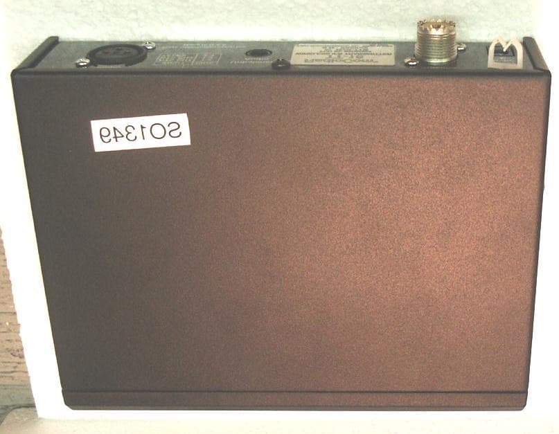
Click to zoom
Application Details
- Equipment Class
- TNB - Licensed Non-Broadcast Station Transmitter
- Date of Grant
- Aug 29, 2005
- Application Purpose
- Original Equipment
- Date of Application
- Aug 29, 2005
- Equipment Note
- Wireless Microphone
- Frequency Range
- 64.00000000 - 68.00000000
- Company
- Bosch Security Systems, Inc.
- Country
- United States
Documents & Files
Document Text
Text extracted from the exhibit documents filed with the FCC. Open a document above to read the original.
Users Manual
Preliminary Operating Instructions Telex Model TT-16 Transmitter Carefully unpack your IFB Transmitter. If there is any damage or shortages, please refer to the “Warranty Service Information”. Set-up Instructions: Power: Power will be received from the supplied “wall cube”. Before applying power, it is suggested that all input cords be plugged in and the antenna be screwed onto the transmitter. Insert the cord plug into the transmitter before plugging in the wall cube. The wall cube normally supplied is for 120 V AC, 60 Hz use only. Transmitter Location: Select a suitable location for the transmitter. Try to keep a clear, unobstructed path between the transmitter and the receiver. The transmitter should not be located near metallic objects such as building structures and file cabinets. Locating the transmitter on top of a file cabinet is OK. Avoid high heat sources such as radiators . Antenna : The antenna supplied should be the only antenna used with the TT-16. The antenna is designed to operate in the vertical position. Audio Input : One or both of the audio input connections can be used at the same time. A single modulation limiter serves both inputs. If either input is not used, that input should be “turned off”. Unbalanced only audio sources devices should be plugged into the ¼ in. (quarter inch) Unbalanced Audio input jack located on the rear panel. Tip is “hot” and the barrel is ground. Balanced or unbalance devices should be plugged into the “XLR” jack located on the rear panel. Pin 1 is Common (or ground), Pin 2 and Pin 3 are audio inputs that depend on the type of intercom selected (RTS 1, RTS 2 or Telex). E.D.R. audio : The Telex TT-16 Transmitter is equipped with E.D.R., Enhanced Dynamic Range (companded) audio. This mode greatly improves the Audio Signal to Noise Ratio when the TT-16 is used with the Telex Model TR-16 receiver. The E.D.R. mode must be selected on the transmitter and receiver to be effective. Also, The E.D.R. Mode must be de-selected if the TT-16 is used with older equipment such as the TR- 34 receiver. Telex TT-16 Transmitter Page 2 Frequency/Channel Considerations: As with any radio device, interference can occur at any time. The frequencies offered are shared with other legitimate users. Check the frequency/channel with the matching receiver to see if any interference is present. If interference is present, choose a different channel. The severity of interference varies with location and distance to the interfering station. If the interference is weak on all channels, this is probably acceptable since your transmitter will cover the interference and is unlikely to interfere with other users. Multiple Channel Systems require other considerations but each channel should be checked as above. For best results, locate each transmitter in the area it is to service, and as far apart as possible. Transmitter Operation: Turn the Monitor control down (counter-clockwise). Now that you have checked all of the channels you intend to use, apply power to the transmitter by pressing the Power Button located on the front panel. The Display Screen should now be on. Select the RF Channel on the transmitter to match the receiver channel. Turn the program material on (balance and/or unbalance audio input). Adjust the appropriate Audio Input Level control until loud program material causes the audio level meter to hit 0 dB. This allows sufficient “headroom” to prevent peak distortion on loud inputs. Set the High/Low power button to High position initially. Audio Monitor: After the audio input levels have been adjusted in the above procedure, stereo headphones with a ¼ in. plug can be plugged into the Monitor jack. If you wish to monitor the audio program material, turn up the monitor (volume) control to the desired level. The monitor control does not affect the transmitted audio level. System Walk Through: Now that the transmitter is set up, you should be able to hear the program material on the appropriate receiver. Walk the receiver through the area that it is intended to be used in. Check for any noise or interference that would cause undesired operation. Some of the causes of poor performance are listed below. Poor transmitter location. Poor receiver location. Interference. Local AC Line noise. RF “Trouble Spots.” Operating distance beyond system capability. Telex TT-16 Transmitter Page 3 Operating Instructions: When the Power button is pressed, the Channel, Frequency, TX power level, existing audio level settings and intercom type are displayed. After this point, switch functions as follows: Operation Function/Result Press set Channel (“blinks”) flashes. Press up (arrow) Channel increments. Press down (arrow) Channel decrements. Press set Flash stops, Channel is set in memory. Press set RF Power High flashes Press up High power Press down Low power Press set Flash stops, Level is set in memory. High = displayed, Low = Not displayed Press set Unbalanced Audio Level flashes. Press up Audio Level increases at 6 dB per step. Press down Audio Level decreases at 6 dB per step. Press set flash stops, Level is set in memory. Press set Input audio type, RTS 1, RTS 2 or Telx will flash, depending on which source was last selected. Press set again if the flashing source item is the desired item or Press up/down button to select new source. Press set last to save flashing item. Press set Balanced Audio Level flashes. Press up Audio Level increases at 6 dB per step. Press down Audio Level decreases at 6 dB per step. Press set flash stops, Level is set in memory. Press set Input audio type, RTS 1, RTS 2 or Telx will flash, depending on which source was last selected. Press set again if the flashing source item is the desired item or Press up/down button to select new source. Press set last to save flashing item. Special Function Programming : E.D.R. : If E.D.R. does not already show on the display and Enhanced Audio Performance is desired, program as follows: Press the power switch for …
Text truncated - open the document above for the full version.
Cover Letter(s)
Telex Communications, Inc. 8601 E. Cornhusker Hwy Lincoln, NE 68507 402-467-5321 Date: September 26, 2002 To: Federal Communications Commission EQUIPMENT APPROVAL SERVICES P.O. Box 358315 Pittsburgh, PA 15251-5315 To: INDUSTRY CANADA Certification & Engineering Bureau 3701 Carling Avenue, Bldg. 94 P.O. Box 11490, Station “H” Ottawa, Ontario, Canada K2H 8S2 Per: 47 CFR 0.457 and 0.459 Pursuant to Sections 0.457 (d) (1) (ii) and 0.459 of the Commission’s Rules, the applicant hereby requests confidential treatment of some of the information accompanying this application as listed below, i.e. Block Diagram, Schematics, Parts Lists, List of Active Devices, Tune-up Procedures (alignment procedure), Operational Description (theory of operation). These materials contain trade secrets and proprietary information not customarily released to the public and the public disclosure of these matters might be harmful to the applicant and provide unjustified benefits to its competitors. The applicant understands that pursuant to Rule 0.457 (d) (1) (ii) disclosure of this application and all accompanying documentation will not be made before the date of the grant of this application. Sincerely, Charles E. Conner Senior Project Engineer Telex Communications, Inc.
RF Exposure Info
M. Flom Associates, Inc. 3356 N. San Marcos Place, Suite 107 Chandler, Arizona 85225-7176 FCC ID: B5DM524 (480) 926-3100 phone, fax (480) 926-3598 MFA p0580002, d0580033 Date: August 19, 2005 Federal Communications Commission Via: Electronic Filing Attention: Authorization & Evaluation Division Applicant: Telex Communications, Inc. Equipment: TT-16 FCC ID: B5DM524 FCC Rules: Radiofrequency Radiation Exposure Limits 47 CFR 1.1310 MPE - Mobiles X Fixed Based Station Gentlemen: On behalf of the Applicant, enclosed please find the Supplemental Test Data Report, the whole for Environmental Assessment (MPE) of the referenced equipment as shown. We trust the same is in order. Should you need any further information, kindly contact the writer who is authorized to act as agent. Sincerely yours, David E. Lee, Quality Assurance Manager enclosure(s) cc: Applicant DEL/del M. Flom Associates, Inc. 3356 N. San Marcos Place, Suite 107 Chandler, Arizona 85225-7176 FCC ID: B5DM524 (480) 926-3100 phone, fax (480) 926-3598 MFA p0580002, d0580033 Environmental Assessment for Mobiles/Fixed Base Station for FCC ID: FCC ID: B5DM524 Model:TT-16 to Federal Communications Commission 47 CFR 1.1310 (MPE) Radiofrequency Radiation Exposure Limits Date Of Report: August 19, 2005 On the Behalf of the Applicant: Telex Communications, Inc. At the Request of: P.O. 282205 Telex Communications, Inc. 8601 E. Cornhusker Highway P.O. Box 5579 Lincoln, NE 68505-5579 Attention of: Charles E. Conner, Project Engineer (402) 467-5321; FAX: -3279 E-mail: [email protected] Jim Andersen Email: [email protected] Supervised By: David E. Lee, Quality Assurance Manager M. Flom Associates, Inc. 3356 N. San Marcos Place, Suite 107 Chandler, Arizona 85225-7176 FCC ID: B5DM524 (480) 926-3100 phone, fax (480) 926-3598 MFA p0580002, d0580033 Table of Contents Rule Description Page . Test Report 1 . Identification of the Equipment Under Test 2 . Standard Test Conditions and Engineering Practices 4 1.1310 Environmental Assessment 5 M. Flom Associates, Inc. 3356 N. San Marcos Place, Suite 107 Page 1 of 5 Chandler, Arizona 85225-7176 FCC ID: B5DM524 (480) 926-3100 phone, fax (480) 926-3598 MFA p0580002, d0580033 Required information per ISO/IEC Guide 25-1990, paragraph 13.2: a) Test Report (Supplemental) b) Laboratory: (FCC: 31040/SIT) (Canada: IC 2044) M. Flom Associates, Inc. 3356 N. San Marcos Place, Suite 107 Chandler, AZ 85225 c) Report Number: d0580033 d) Client: Telex Communications, Inc. 8601 E. Cornhusker Highway P.O. Box 5579 Lincoln, NE 68505-5579 e) Identification: TT-16 FCC ID: B5DM524 Description: Wireless Mic f) EUT Condition: Not required unless specified in individual tests. g) Report Date: August 19, 2005 EUT Received: August 1, 2005 h, j, k): As indicated in individual tests. i) Sampling method: No sampling procedure used. l) Uncertainty: In accordance with MFA internal quality manual. m) Supervised by: David E. Lee, Quality Assurance Manager n) Results: The results presented in this report relate only to the item tested. o) Reproduction: This report must not be reproduced, except in full, without written permission from this laboratory. M. Flom Associates, Inc. 3356 N. San Marcos Place, Suite 107 Page 2 of 5 Chandler, Arizona 85225-7176 FCC ID: B5DM524 (480) 926-3100 phone, fax (480) 926-3598 MFA p0580002, d0580033 Identification of the Equipment Under Test (EUT) Name and Address of Applicant: Telex Communications, Inc. 8601 E. Cornhusker Highway P.O. Box 5579 Lincoln, NE 68505-5579 Manufacturer: Applicant FCC ID: B5DM524 Model Number: TT-16 Description: Wireless Mic Type of Emission: 60K0F3E Frequency Range, MHz: 64 to 68 Power Rating, Watts: 0.05 Switchable x Variable N/A Modulation: AMPS TDMA CDMA X OTHER Antenna: Helical Monopole X Whip Other Note: For RF Safety test antenna gain taken at the upper range of expected gain (i.e. 0 dBi) and RF Power set to highest nominal power across all channels. M. Flom Associates, Inc. 3356 N. San Marcos Place, Suite 107 Page 3 of 5 Chandler, Arizona 85225-7176 FCC ID: B5DM524 (480) 926-3100 phone, fax (480) 926-3598 MFA p0580002, d0580033 A2LA “A2LA has accredited M. Flom Associates, Inc. Chandler, AZ for technical competence in the field of Electrical Testing. The accreditation covers the specific tests and types of tests listed on the agreed scope of accreditation. This laboratory meets the requirements of ISO/IEC 17025 – 1999 ‘General Requirements for the Competence of Testing and Calibration Laboratories’ and any additional program requirements in the identified field of testing.” Certificate Number: 2152-01 NIST I am pleased to inform you that your laboratory has been validated by the Chinese Taipei Bureau of Standards, Metrology and Inspection (BSMI) under the Asia Pacific Economic Cooperation Mutual Recognition Agreement (APEC MRA). Your laboratory is now formally designated to act as a Conformity Assessment Body (CAB) under Appendix B, Phase I Procedures, of the APEC MRA between the American Institute in Taiwan (AIT) and the Taipei Economic and Cultural Representative Office (TECRO) in the United States, covering equipment subject to Electro-Magnetic Compatibility (EMC) requirements. The names of all validated and nominated laboratories will be posted on the NIST website at http://ts.nist.gov/mra under the ‘Asia’ category.” BSMI Number: SL2-IN-E-041R M. Flom Associates, Inc. 3356 N. San Marcos Place, Suite 107 Page 4 of 5 Chandler, Arizona 85225-7176 FCC ID: B5DM524 (480) 926-3100 phone, fax (480) 926-3598 MFA p0580002, d0580033 Standard Test Conditions and Engineering Practices Except as noted herein, the following conditions and procedures were observed during the testing: In accordance with ANSI C63.4-1992/2000, section 6.1.9, and unless otherwise indicated in the specific measurement results, the ambient temperature of the actual EUT was maintained within the range of 10° to 40°C (50° to 104 °F) unless the particular equipment requirements specify testing over a diff…
Text truncated - open the document above for the full version.
Test Report
M. Flom Associates, Inc. 3356 N. San Marcos Place, Suite 107 Chandler, Arizona 85225-7176 FCC ID: B5DM524 (480) 926-3100 phone, fax (480) 926-3598 MFA p0580002, d0580055 Date: August 2, 2005 Federal Communications Commission Via: Electronic Filing Attention: Authorization & Evaluation Division Applicant: Telex Communications, Inc. Equipment: TT-16 FCC ID: B5DM524 FCC Rules: 74H Gentlemen: On behalf of the Applicant, enclosed please find Application Form 731, Engineering Test Report and all pertinent documentation, the whole for approval of the referenced equipment as shown. Filing fees are attached. We trust the same is in order. Should you need any further information, kindly contact the writer who is authorized to act as agent. Sincerely yours, David E. Lee, Quality Assurance Manager enclosure(s) cc: Applicant DEL/del M. Flom Associates, Inc. 3356 N. San Marcos Place, Suite 107 Chandler, Arizona 85225-7176 FCC ID: B5DM524 (480) 926-3100 phone, fax (480) 926-3598 MFA p0580002, d0580055 Transmitter Certification of FCC ID: B5DM524 Model: TT-16 to Federal Communications Commission Rule Part(s) 74H Date of report: August 11, 2005 On the Behalf of the Applicant: Telex Communications, Inc. At the Request of: P.O. 282205 Telex Communications, Inc. 8601 E. Cornhusker Highway P.O. Box 5579 Lincoln, NE 68505-5579 Attention of: Charles E. Conner, Project Engineer (402) 467-5321; FAX: -3279 E-mail: [email protected] Jim Andersen Email: [email protected] Supervised by: David E. Lee, Quality Assurance Manager M. Flom Associates, Inc. 3356 N. San Marcos Place, Suite 107 Chandler, Arizona 85225-7176 FCC ID: B5DM524 (480) 926-3100 phone, fax (480) 926-3598 MFA p0580002, d0580055 List of Exhibits (FCC Certification (Transmitters) - Revised 9/28/98) Applicant: Telex Communications, Inc. FCC ID: B5DM524 By Applicant: 1. Letter of Authorization 2. Confidentiality Request: 0.457 And 0.459 3. Identification Drawings, 2.1033(c)(11) Label Location of Label Compliance Statement Location of Compliance Statement 4. Photographs, 2.1033(c)(12) 5. Documentation: 2.1033(c) (3) User Manual (9) Tune Up Info (10) Schematic Diagram (10) Circuit Description Block Diagram Parts List Active Devices 6. MPE Report By M.F.A. Inc.: A. Testimonial & Statement of Certification M. Flom Associates, Inc. 3356 N. San Marcos Place, Suite 107 Chandler, Arizona 85225-7176 FCC ID: B5DM524 (480) 926-3100 phone, fax (480) 926-3598 MFA p0580002, d0580055 The Applicant has been cautioned as to the following: 15.21 Information to the User. The users manual or instruction manual for an intentional radiator shall caution the user that changes or modifications not expressly approved by the party responsible for compliance could void the user's authority to operate the equipment. 15.27(a) Special Accessories. Equipment marketed to a consumer must be capable of complying with the necessary regulations in the configuration in which the equipment is marketed. Where special accessories, such as shielded cables and/or special connectors are required to enable an unintentional or intentional radiator to comply with the emission limits in this part, the equipment must be marketed with, i.e. shipped and sold with, those special accessories. However, in lieu of shipping or packaging the special accessories with the unintentional or intentional radiator, the responsible party may employ other methods of ensuring that the special accessories are provided to the consumer, without additional charge. Information detailing any alternative method used to supply the special accessories for a grant of equipment authorization or retained in the verification records, as appropriate. The party responsible for the equipment, as detailed in § 2.909 of this chapter, shall ensure that these special accessories are provided with the equipment. The instruction manual for such devices shall include appropriate instructions on the first page of text concerned with the installation of the device that these special accessories must be used with the device. It is the responsibility of the user to use the needed special accessories supplied with the equipment. M. Flom Associates, Inc. 3356 N. San Marcos Place, Suite 107 Chandler, Arizona 85225-7176 FCC ID: B5DM524 (480) 926-3100 phone, fax (480) 926-3598 MFA p0580002, d0580055 Table of Contents Rule Description Page 2.1033(c)(14) Rule Summary 2 . Standard Test Conditions and Engineering Practices 3 2.1033(c) General Information Required 5 2.1046(a) Carrier Output Power (Conducted) 7 2.1046(a) RF Power Output (Radiated) 9 2.1053(a) Field Strength of Spurious Radiation 10 2.1049(c)(1) Emission Masks (Occupied Bandwidth) 14 2.1055(a)(1) Frequency Stability (Temperature Variation) 16 2.1055(b)(1) Frequency Stability (Voltage Variation) 18 2.202(g) Necessary Bandwidth and Emission Bandwidth 20 M. Flom Associates, Inc. 3356 North San Marcos Place, Suite 107 Page 1 of 20 Chandler, Arizona 85225-7176 FCC ID: B5DM524 (480) 926-3100 phone, (480) 926-3598 fax MFA p0580002, d0580055 Required information per ISO/IEC Guide 25-1990, paragraph 13.2: a) Test Report b) Laboratory: (FCC: 31040/SIT) (Canada: IC 2044) M. Flom Associates, Inc. 3356 N. San Marcos Place, Suite 107 Chandler, AZ 85225 c) Report Number: d0580055 d) Client: Telex Communications, Inc. 8601 E. Cornhusker Highway P.O. Box 5579 Lincoln, NE 68505-5579 e) Identification: TT-16 FCC ID: B5DM524 EUT Description: Wireless Mic f) EUT Condition: Not required unless specified in individual tests. g) Report Date: August 11, 2005 EUT Received: July 29, 2005 h, j, k): As indicated in individual tests. i) Sampling method: No sampling procedure used. l) Uncertainty: In accordance with MFA internal quality manual. m) Supervised by: David E. Lee, Quality Assurance Manager n) Results: The results presented in this report relate only to the item tested. o) Reproduction: This report must not be reproduced, except in full, without written permission from this laboratory. M. Flom Assoc…
Text truncated - open the document above for the full version.
Contact Information
Applicant
James R Andersen(Principal Electrical Engineer)
Technical Contact
M. Flom Associates, Inc.David Lee
[email protected]480-926-3100
3356 N. San Marcos Place, Suite 107 · Chandler, Arizona · United States
Test Firm
M. Flom Associates, Inc.Morton Flom
Technical Specifications
| # | Rule Parts | Frequency Range | Power Output | Emission | Tolerance |
|---|---|---|---|---|---|
| 1 | 74 | 64 MHz - 68 MHz | 50.00 mW | 60K0F3E | 50.0000000000 ppm |
Other Applications from Bosch Security Systems, Inc.

B5DM540
Jun 02, 2020Wireless microphone base station
Equipment Class
TLD - Licensed LPAS Device
B5DM542
Jun 01, 2020Wireless beltpack
Equipment Class
TLD - Licensed LPAS Device
B5DM541
May 27, 2020Wireless beltpack
Equipment Class
TLD - Licensed LPAS Device
B5DM536
Mar 18, 2020Single Receiver UHF Wireless Intercom Beltpack
Equipment Class
TLD - Licensed LPAS Device
B5DM539
Mar 18, 2020Dual Receiver Narrowband UHF Wireless Intercom Beltpack
Equipment Class
TLD - Licensed LPAS Device