B5DM5252.4GHz ACCESS POINT
Bosch Security Systems, Inc.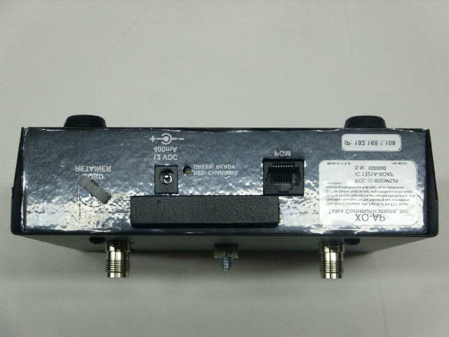
Click to zoom
Application Details
- Equipment Class
- DSS - Part 15 Spread Spectrum Transmitter
- Date of Grant
- Feb 14, 2006
- Application Purpose
- Original Equipment
- Date of Application
- Feb 14, 2006
- Equipment Note
- 2.4GHz ACCESS POINT
- Frequency Range
- 2412.00000000 - 2462.00000000
- Company
- Bosch Security Systems, Inc.
- Country
- United States
Documents & Files
Document Text
Text extracted from the exhibit documents filed with the FCC. Open a document above to read the original.
Users Manual
Page 1 of 3 Telex Model XO-AP Access Point General Description: The Telex model XO-AP transceiver is intended for use as an access point between multiple XO-1 beltpacks clients. This enables the beltpacks to communicate with each other over-the-air. The XO-AP uses 802.11 technology to receive / transmit within one channel of the 1 – 11 (2.412 to 2.462 GHz) channels of the 2.4 GHz ISM band. Its operation is license free. The transmit and receive antennas are connected via reverse TNC connectors on the top of the unit. The XO-AP is powered via an internal Li- Ion battery that will provide up to 14 hours of run time at room temperature. It may also be run off the AC charger unit supplied with the system. The front panel provides an on/off switch, a power light, an AP active light, an RF channel display and a pushbutton for changing RF channels. 1. On/Off Switch– Turns the power on/off to the AP. 2. Battery Light – a. GREEN - Battery OK b. RED - Battery Low (needs charged) 3. Receive Antenna Jack (Not Pictured) – This reverse TNC jack is where the receive antenna coaxial cable should be connected. 4. AP Active Light – This light flashing indicates that the AP has successfully booted. 5. RF Channel Display – The display indicates the 802.11 channel for which the unit is set. 6. Transmit Antenna Jack (Not Pictured) – This reverse TNC jack is where the transmit antenna coaxial cable should be connected. 7. RF Channel Button – a. Channel – Hit the button to select the desired RF channel for the AP. b. ClearScan – Press and hold the button until the decimal point starts to flash (about 4 seconds) then release. The unit will examine the eleven RF channels and then pick the one with the least activity and set the AP on that channel. c. Lock – Press and hold the button until the decimal point is on solid (about 10 seconds) then release. The AP will be lock on the channel displayed. To unlock, press and hold the button again until the decimal point is off. Lock only makes the currently displayed channel hard for a user to accidentally change the RF channel. 1 2 3 4 5 Front Panel 67 Page 2 of 3 8. Charge Jack – Used to charge the internal battery or power the unit directly off a wall outlet. Accepts a 5.5mm x 2.5mm plug with the center positive. Must be supplied with a 12VDC regulated power supply with at least a 400mA current capacity. 9. Charge Light . a. RED =Beltpack battery is charging. b. GREEN = Beltpack battery is charged. 10. Programming Jack – This RJ-45 jack is used to update programming in the unit if ever needed. Operation When the XO-AP is turned on the power light will turn green immediately indicating power. After 20 seconds, the unit will do a ClearScan of the 802.11 RF channels. It will then select the clearest channel. After this is done, the AP active light will start flashing. The AP is now ready to act as an access point for XO-1 beltpacks. 8 9 10 Page 3 of 3 Specifications Technology............................................. 2.4 GHz, IEEE 802.11b Power.................................................... Internal Li-Ion 7.2V, 4000mAhr, Battery. Typical battery life of 14 hours. Current Draw........................................... 285mA typical with radio card active RF Frequency Range.................................. 802.11 Channels 1 – 11 (2.412 to 2.462GHz) Modulation Technology.............................. DBPSK, DQPSK, CCK Antenna Connectors................................... Reverse TNC Jacks RF Output Power (Terminated)..................... 200mW (Maximum) Data rates............................................... 2 and 5.5 Mbps Sensitivity (Worst case).............................. 5.5Mbps, <-91dBm Access Point Size..................................... 6.00L x 6.40W x 2.00H inches Access Point Weight.................................. 1 lb 2oz FCC License............................................ No License Required Regulatory Information This device complies with Part 15 of FCC rules and Canada RSS-210. Operation is subject to the following conditions: 1. This device may not cause harmful interference. 2. This device must accept any interference received, including interference that may cause undesired operation. 3. Use only the manufacturer or dealer supplied antenna. 4. This equipment complies with FCC radiation exposure limits set forth for an uncontrolled environment. The antennas used with this equipment should be installed and operated with a minimum distance of 20cm between the antenna and your body. 5. This device must not be co-located or operated in conjunction with any other antenna or transmitter. To assure continued compliance with FCC regulations, any changes or modification not expressly approved by the party responsible for compliance could void the user’s authority to operate this equipment.
Cover Letter(s)
Telex Communications, Inc. 8601 E. Cornhusker Hwy Lincoln, NE 68507 402-467-5321 Date: February 9, 2006 To: Federal Communications Commission EQUIPMENT APPROVAL SERVICES P.O. Box 358315 Pittsburgh, PA 15251-5315 To: INDUSTRY CANADA Certification & Engineering Bureau 3701 Carling Avenue, Bldg. 94 P.O. Box 11490, Station “H” Ottawa, Ontario, Canada K2H 8S2 Per: 47 CFR 0.457 and 0.459 Pursuant to Sections 0.457 (d) (1) (ii) and 0.459 of the Commission’s Rules, the applicant hereby requests confidential treatment of some of the information accompanying this application as listed below, i.e. Block Diagram, Schematics, Parts Lists, List of Active Devices, Operational Description These materials contain trade secrets and proprietary information not customarily released to the public and the public disclosure of these matters might be harmful to the applicant and provide unjustified benefits to its competitors. The applicant understands that pursuant to Rule 0.457 (d) (1) (ii) disclosure of this application and all accompanying documentation will not be made before the date of the grant of this application. Sincerely, Charles E. Conner Senior Project Engineer Telex Communications, Inc.
Test Report
Flom Test Labs 3356 N. San Marcos Place, Suite 107 Chandler, Arizona 85225-7176 FCC ID: B5DM525 (866) 311-3268 phone, (480) 926-3598 fax MFA p0610001, d0610021 Date of Report: Date of Submission: January 17, 2006 February 9, 2006 Federal Communications Commission Via: Electronic Filing Attention: Authorization & Evaluation Division Applicant: Telex Communications, Inc. Equipment: X0-AP FCC ID: B5DM525 FCC Rules: 15.247 Gentlemen: On behalf of the Applicant, enclosed please find Application Form 731, Engineering Test Report and all pertinent documentation, the whole for approval of the referenced equipment as shown. Filing fees are attached. We trust the same is in order. Should you need any further information, kindly contact the writer who is authorized to act as agent. Sincerely yours, David E. Lee, FCC Compliance Manager enclosure(s) cc: Applicant DEL/del Flom Test Labs 3356 N. San Marcos Place, Suite 107 Chandler, Arizona 85225-7176 FCC ID: B5DM525 (866) 311-3268 phone, (480) 926-3598 fax MFA p0610001, d0610021 Transmitter Certification of FCC ID: B5DM525 Model: X0-AP to Federal Communications Commission Rule Part(s) 15.247 Date Of Report: January 17, 2006 On the Behalf of the Applicant: Telex Communications, Inc. At the Request of: P.O. 336057 Telex Communications, Inc. 8601 E. Cornhusker Highway P.O. Box 5579 Lincoln, NE 68505-5579 Attention of: Charles E. Conner, Project Engineer (402) 467-5321; FAX: -3279 E-mail: [email protected] Jim Andersen Email: [email protected] Supervised By: David E. Lee, FCC Compliance Manager M. Flom Associates, Inc. 3356 N. San Marcos Place, Suite 107 Chandler, Arizona 85225-7176 FCC ID: B5DM525 (480) 926-3100 phone, fax (480) 926-3598 MFA p0610001, d0610021 List Of Exhibits (FCC Certification (Transmitters) - Revised 9/28/98) Applicant: Telex Communications, Inc. FCC ID: B5DM525 By Applicant: 1. Letter Of Authorization 2. Identification Drawings Id Label Location Info Attestation Statement Location of Compliance Statement 3. Documentation: 2.1033(B) (3) User Manual (4) Operational Description (5) Block Diagram (5) Schematic Diagram (7) External Photographs Internal Photographs Parts List Active Devices By M.F.A. Inc. A. Testimonial & Statement of Certification M. Flom Associates, Inc. 3356 N. San Marcos Place, Suite 107 Chandler, Arizona 85225-7176 FCC ID: B5DM525 (480) 926-3100 phone, fax (480) 926-3598 MFA p0610001, d0610021 The applicant has been cautioned as to the following: 15.21 Information to User. The users manual or instruction manual for an intentional radiator shall caution the user that changes or modifications not expressly approved by the party responsible for compliance could void the user's authority to operate the equipment. 15.27(a) Special Accessories. Equipment marketed to a consumer must be capable of complying with the necessary regulations in the configuration in which the equipment is marketed. Where special accessories, such as shielded cables and/or special connectors are required to enable an unintentional or intentional radiator to comply with the emission limits in this part, the equipment must be marketed with, i.e. shipped and sold with, those special accessories. However, in lieu of shipping or packaging the special accessories with the unintentional or intentional radiator, the responsible party may employ other methods of ensuring that the special accessories are provided to the consumer, without additional charge. Information detailing any alternative method used to supply the special accessories for a grant of equipment authorization or retained in the verification records, as appropriate. The party responsible for the equipment, as detailed in § 2.909 of this chapter, shall ensure that these special accessories are provided with the equipment. The instruction manual for such devices shall include appropriate instructions on the first page of text concerned with the installation of the device that these special accessories must be used with the device. It is the responsibility of the user to use the needed special accessories supplied with the equipment. M. Flom Associates, Inc. 3356 N. San Marcos Place, Suite 107 Chandler, Arizona 85225-7176 FCC ID: B5DM525 (480) 926-3100 phone, fax (480) 926-3598 MFA p0610001, d0610021 Table Of Contents Rule Description Page . Test Report 2 2.1033(c) General Information Required 3 . Standard Test Conditions and Engineering Practices 6 2.1046(a) Carrier Output Power (Conducted) 7 ANSI C63.4/2003 Carrier Power (Radiated) 9 2.1053(a) Field Strength of Spurious Radiation 12 2.1049(c)(1) Emission Masks (Occupied Bandwidth) 16 15.207 A/C Powerline Conducted Emissions 26 2.202(g) Necessary Bandwidth and Emission Bandwidth 30 1.1310. Radio Frequency Radiation Exposure Evaluation 31 M. Flom Associates, Inc. 3356 N. San Marcos Place, Suite 107 Page 2 of 31 Chandler, Arizona 85225-7176 FCC ID: B5DM525 (480) 926-3100 phone, fax (480) 926-3598 MFA p0610001, d0610021 Required information per ISO/IEC Guide 25-1990, paragraph 13.2: a) Test Report b) Laboratory: (FCC: 31040/SIT) (Canada: IC 2044) M. Flom Associates, Inc. 3356 N. San Marcos Place, Suite 107 Chandler, AZ 85225 c) Report Number: d0610021 d) Client: Telex Communications, Inc. 8601 E. Cornhusker Highway P.O. Box 5579 Lincoln, NE 68505-5579 e) Identification: X0-AP FCC ID: B5DM525 Description: 2.4MHz Access Point f) EUT Condition: Not required unless specified in individual tests. g) Report Date: January 17, 2006 EUT Received: January 10, 2006 h, j, k): As indicated in individual tests. i) Sampling method: No sampling procedure used. l) Uncertainty: In accordance with MFA internal quality manual. m) Supervised by: David E. Lee, FCC Compliance Manager n) Results: The results presented in this report relate only to the item tested. o) Reproduction: This report must not be reproduced, except in full, without written permission from this laboratory. M. Flom Associates, Inc. 3356 N. San Marcos Place, Suite 107 Page 3 of 31…
Text truncated - open the document above for the full version.
Test Setup Photos
M. Flom Associates, Inc. 3356 N. San Marcos Place, Suite 107 Page 11 of 31 Chandler, Arizona 85225-7176 FCC ID: B5DM525 (480) 926-3100 phone, fax (480) 926-3598 MFA p0610001, d0610021 Name of Test: Spurious Radiation M. Flom Associates, Inc. 3356 N. San Marcos Place, Suite 107 Page 27 of 31 Chandler, Arizona 85225-7176 FCC ID: B5DM525 (480) 926-3100 phone, fax (480) 926-3598 MFA p0610001, d0610021 Name of Test: A/C Powerline Conducted Emissions
Contact Information
Applicant
James R Andersen(Principal Electrical Engineer)
Test Firm
M. Flom Associates, Inc.Morton Flom
Technical Specifications
| # | Rule Parts | Frequency Range | Power Output |
|---|---|---|---|
| 1 | 15C | 2.41 GHz - 2.46 GHz | 200.00 mW |
Other Applications from Bosch Security Systems, Inc.

B5DM540
Jun 02, 2020Wireless microphone base station
Equipment Class
TLD - Licensed LPAS Device
B5DM542
Jun 01, 2020Wireless beltpack
Equipment Class
TLD - Licensed LPAS Device
B5DM541
May 27, 2020Wireless beltpack
Equipment Class
TLD - Licensed LPAS Device
B5DM536
Mar 18, 2020Single Receiver UHF Wireless Intercom Beltpack
Equipment Class
TLD - Licensed LPAS Device
B5DM539
Mar 18, 2020Dual Receiver Narrowband UHF Wireless Intercom Beltpack
Equipment Class
TLD - Licensed LPAS Device