B5DM533Wireless 2.4 GHz Beltpack
Bosch Security Systems, Inc.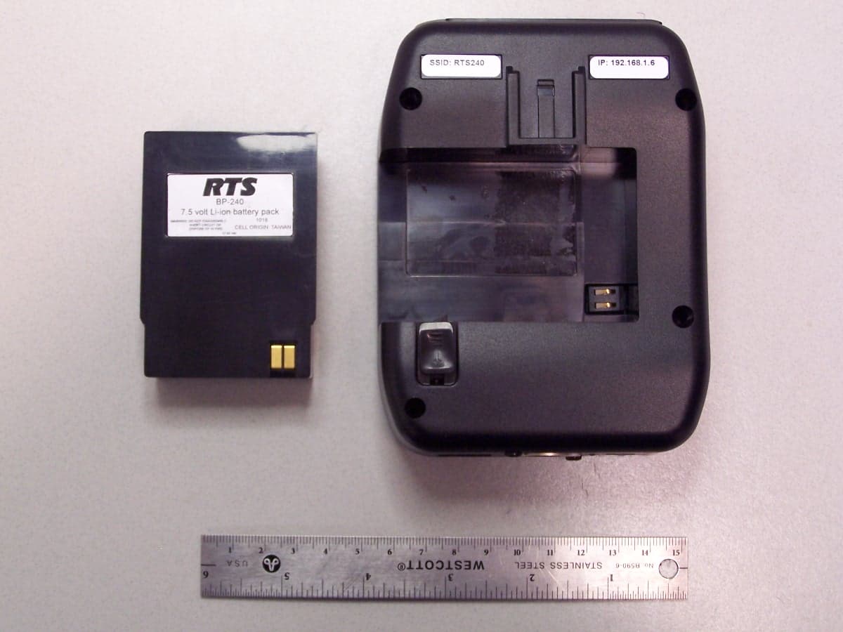
Click to zoom
Application Details
- Equipment Class
- DTS - Digital Transmission System
- Date of Grant
- Apr 06, 2011
- Application Purpose
- Original Equipment
- Date of Application
- Apr 06, 2011
- Equipment Note
- Wireless 2.4 GHz Beltpack
- Frequency Range
- 2412.00000000 - 2462.00000000
- Company
- Bosch Security Systems, Inc.
- Country
- United States
Documents & Files
Document Text
Text extracted from the exhibit documents filed with the FCC. Open a document above to read the original.
Users Manual
TR-240 Users Manual - Preliminary Page 1 of 7 Rev D – 3 / 09 / 2011 RTS Model TR-240 Beltpack Owners / Users Manual (Preliminary Information) General Description The RTS model TR-240 beltpack transceiver is intended for use as a wireless full-duplex intercom radio to be worn on a belt. Multiple TR-240 beltpacks can be used with a BTR-240 base station transceiver or a BTR-24 access point to communicate with each other over-the-air. The TR-240 uses the IEEE 802.11b technology to transmit / receive within one channel of the 1 – 11 (2.412 to 2.462 GHz) allowable channels of the 2.4 GHz ISM band. Its operation is license free. The typical line-of-sight distances for the system may be 300 feet. The transmit and receive antennas are internal to the beltpack so the unit has a smaller profile. The outer case also provides extra protection against possible damage to the antennas. The TR-240 is powered via an internal Li- Ion battery that will provide up to 8 hours of run time at room temperature. The top panel provides on/off/volume control, channel select buttons and lights, talk button and battery status light. TR-240 Users Manual - Preliminary Page 2 of 7 Rev D – 3 / 09 / 2011 Controls and Connections 1. On/Off & Volume Control – Turns the beltpack power on/off and controls headset volume. 2. Battery Light – a. GREEN = Battery OK b. YELLOW = Battery Low (approx. 15 mins of use left) c. RED = Battery Low (needs charged) 3. Channel 1 “Green” Button and Light – Selects the “Channel 1” intercom. The green light next to the button will illuminate upon selection. 4. Talk Button – When pressed the microphone path is enabled. a. Momentary – Pressed and hold for over ½ second. b. Latch on/off – Tap button and the microphone path is enabled. Tap again to turn off. The active intercom channel light will remain illuminated when the microphone path is enabled. The active intercom channel light will blink when the microphone path is disabled. 5. Channel 2 “Blue” Button and Light – Selects the “Channel 2” intercom. The green light next to the button will illuminate upon selection. 6. Charge Jack – Used to charge the Li-Ion battery. Accepts a 5.5mm x 2.5mm plug with the center positive. Must be supplied with a 12VDC regulated power supply with at least a 400mA current capacity. 7. Charge Light . a. RED = Beltpack battery is charging. b. GREEN = Beltpack battery is charged. 8. Headset Connector – Standard 4-pin XLR connector. a. Pin 1 = Microphone GND b. Pin 2 = Microphone HOT c. Pin 3 = Headphone + d. Pin 4 = Headphone – 9. Programming Jack – This RJ-45 jack is used for wired Ethernet connections, configuration, and to update programming in the unit if ever needed. 1 3 4 5 2 6 8 97 Top View Bottom View TR-240 Users Manual - Preliminary Page 3 of 7 Rev D – 3 / 09 / 2011 Operation Once a BTR-240 or BTR-24 is running, the TR- 240 may be switched on at anytime. The TR- 240 has key features that can be set during boot and after the unit has booted. These settings include the following: • Mode of Operation • Local Headset Configuration 1 Setting the Beltpack Mode The TR-240 has three different and selectable modes of operation: “wireless” mode, “wired” mode, and “master wireless” mode. The normal mode is “wireless”. A TR-240 beltpack is configured to boot in one of these modes by holding a specific button sequence while the unit is booting. NOTE: Once the TR-240 mode is set, it will continue to boot in that mode until different mode is selected on startup. 1.1 “Wireless” (Normal) Mode In this configuration, a base station or access point provides wireless coverage over the area in which the beltpacks will be used. 1. Ensure that a BTR-240 base station or BTR-24 access point is configured and running the in the desired coverage area of use. 2. Turn on the TR-240. The battery light will turn green immediately indicating power. 3. To place the TR-240 in “wireless” mode, if not already set, press and hold the <Talk> button as the beltpack boots. 4. After 20 seconds boot time, a voice prompt “wireless” will be heard in the headphone and the “Channel 1” button light will activate indicating the unit is running. 5. Release the <Talk> button if it is being pressed. 6. Use as normal. NOTE: In “wireless” mode, the wired Ethernet port is disabled. 1.2 “Wired” Mode Beltpacks are directly connected to each other via an Ethernet cable or through a building’s Ethernet infrastructure. In “wired” mode, the wireless transmitter is disabled. 1. Connect the TR-240 to an existing wired network or computer using a standard Ethernet cable. 2. Turn on the beltpack. The battery light will turn green immediately indicating power. 3. To place the TR-240 in “wired” mode, if not already set, press and hold the <2> (blue) button as the beltpack boots. 4. After 20 seconds boot time, a voice prompt “wired” will be heard in the headphone, followed by the current software version. 5. Release the <2> button if it is being pressed. 6. Use as normal. NOTE: In “wired” mode, the wireless transmitter is disabled. 1.3 “Master Wireless” Mode A beltpack can be configured to act as a base station and eliminate the need to have an actual BTR-240 base station or BTR-24 access point. This “master” beltpack may still be used for audio just as a normal beltpack. In “master wireless” mode, the wired Ethernet port is disabled. TR-240 Users Manual - Preliminary Page 4 of 7 Rev D – 3 / 09 / 2011 1. Turn on the TR-240. The battery light will turn green immediately indicating power. 2. To place the TR-240 in “master wireless” mode, if not already set, press and hold the <1> (green) button as the beltpack boots. 3. After 20 seconds boot time, a voice prompt “master wireless” will be heard in the headphone, followed by the current RF channel (“channel xx”) of operation. 4. Release the <1> button after the voice prompt indicates the RF channel. 5. Use as normal. NOTE: In “master wireless” mode, the wired Ethernet port is disabled. 1.3.1 Setting the RF Channel For a beltpac…
Text truncated - open the document above for the full version.
External Photos
Top View Front View Rear View Rear View with Battery Removed Bottom View
ID Label/Location Info
Dynacord | Electro-Voice | RTS | Telex BOSCH and the symbol are registered trademarks of Robert Bosch GmbH, Germany Bosch Security Systems, Inc. 8601 East Cornhusker Highway Lincoln, NE 68507, USA Tel. +1 402 467 5321 x6671 Fax +1 402 467 3279 [email protected] www.boschcommunications.com Communications Systems TR-240 Label Location
Internal Photos
Main Overview Main Overview with Top Switch PCB Top Switch PCB - Top View Top Switch PCB - Bottom View Main PCB - Top View Main PCB with RF Card - Bottom View Main PCB without RF Card - Bottom View
Internal Photos
RF Card - Top View RF Card - Bottom View RF Card with Internal Shield - Top View RF Card without Internal Shield - Top View RF Card - Bottom View
Operational Description
t 2.4 GHz 2 dBi Internal Antenna MODEL: X0-1 ANT PART No: 880162 General Description This is a 2.4 GHz, 2 dBi gain, omni-directional pattern antenna used internally to the TR-240, TR-24 and XO-1 beltpacks. Specifications Electrical Frequency 2.4 GHz – 2.5 GHz Antenna Gain 2 dBi Horizontal Pattern Omni-directional Vertical Pattern 70° (-3 dB bandwidth) VSWR < 2:1 Polarization Vertical, Linear Impedance 50 Ohm Mechanical Connector MMCX Right Angle Plug Pigtail Length 7.65” (194.3 mm) Length (Antenna) 2.00” (51 mm) Diameter (Antenna) 0.2” (5.1 mm) RoHS Compliant Operating Temperature -40° C to 85° C (-40° F to 185° F) Bosch Security Systems reserves the right to make specification changes without notice. Bosch Security Systems, Inc. 8601 East Cornhusker Highway Lincoln, NE 68507 Printed in U.S.A. Rev C 2011
RF Exposure Info
Compliance Testing 3356 N. San Marcos Place, Suite 107 Chandler, Arizona 85225-7176 (866) 311-3268 phone, (480) 926-3598 fax p10b0010, d1110034 Rev 2.0 Date: January 28, 2011 Applicant: Bosch Security Systems, Inc 8601 E. Cornhusker Highway Lincoln, NE 68507 Attention of: James Andersen, Principal Electrical Engineer Ph: (402) 467-5321 Fax: (402) 467-3279 Email: [email protected] Equipment: TR-240 FCC ID: B5DM533 FCC Rules: Radio Frequency Radiation Exposure Limits 47 CFR 1.1307 RF Exposure Statement 1. Standard Applicable According to 1.1307 (b)(1), systems operating under the provisions of this section shall be operated in a manner that ensure that the public is not exposed to radio frequency energy level in excess of the Commission’s guideline. This is a portable device. 2. Description The Telex model TR-240 beltpack transceiver is intended for use as a wireless full-duplex intercom radio to be worn on a belt. The beltpack contains a 2.4 GHz DTS wireless transmitter. 3. Measurement Result Tuned Frequency Conducted Peak Output power MPE Power Limit 2412 MHz 19.77 mW 24.875 mW 2437 MHz 18.28 mW 24.620 mW 2462 MHz 16.87 mW 24.370 mW This is a portable device and the max peak output power is 12.96 dBm (.01977 W). The peak output power is lower than the low threshold of 60/f GHz = (24.875 mW), for d<2.5 cm general population category. 4. The SAR/MPE measurement is not necessary.
Test Report
p10b0010, d1110005 Rev 2.0 Date: January 6, 2011 Applicant: Bosch Security Systems, Inc 8601 E. Cornhusker Highway Lincoln, NE 68507 Attention of: James Andersen, Principal Electrical Engineer Ph: (402) 467-5321 Fax: (402) 467-3279 Email: [email protected] Equipment: TR-240 FCC ID: B5DM533 FCC Rules: 15.247 Enclosed please find your copy of the Engineering Test Report for which you are subject to the restrictions as listed on the attached summary. This report may not be reproduced, except in full, without written permission from Compliance Testing, LLC. Please retain a copy of this report for your archival purposes. Once a Telecommunication Certification Body (TCB) issues a Grant the Federal Communication Commission (FCC) has 30 days to review the application and request added information. It is your decision whether or not to market the equipment subject to a possible recall before the end of the 30 days. If your equipment is still retained by us, it will be returned to you 30 days after approval is achieved. Our invoice for services has been directed to your Accounts Payable Department. For any additional information please contact us. Sincerely, Compliance Testing p10b0010, d1110005 Rev 2.0 Test Report for FCC ID: B5DM533 Model: TR-240 to Federal Communications Commission Rule Part(s) 15.247 Date of Report: January 6, 2011 On the Behalf of the Applicant: Bosch Security Systems, Inc 8601 E. Cornhusker Highway Lincoln, NE 68507 Attention of: James Andersen, Principal Electrical Engineer Ph: (402) 467-5321 Fax: (402) 467-3279 Email: [email protected] By Compliance Testing, LLC 3356 N. San Marcos Place, Suite 107 Chandler, Arizona 85225-7176 (866) 311-3268 phone, (480) 926-3598 fax p10b0010, d1110005 Rev 2.0 Test Report Revision History Revision Date Revised By Reason for revision 1.0 January 27, 2011 Greg Corbin Original Document 2.0 March 8, 2011 Greg Corbin Corrected test set-up information for peak output power p10b0010, d1110005 Rev 2.0 The applicant has been cautioned as to the following: 15.21 Information to User The user’s manual or instruction manual for an intentional radiator shall caution the user that changes or modifications not expressly approved by the party responsible for compliance could void the user's authority to operate the equipment. 15.27(a) Special Accessories Equipment marketed to a consumer must be capable of complying with the necessary regulations in the configuration in which the equipment is marketed. Where special accessories, such as shielded cables and/or special connectors are required to enable an unintentional or intentional radiator to comply with the emission limits in this part, the equipment must be marketed with, i.e. shipped and sold with, those special accessories. However, in lieu of shipping or packaging the special accessories with the unintentional or intentional radiator, the responsible party may employ other methods of ensuring that the special accessories are provided to the consumer, without additional charge. Information detailing any alternative method used to supply the special accessories for a grant of equipment authorization or retained in the verification records, as appropriate. The party responsible for the equipment, as detailed in § 2.909 of this chapter, shall ensure that these special accessories are provided with the equipment. The instruction manual for such devices shall include appropriate instructions on the first page of text concerned with the installation of the device that these special accessories must be used with the device. It is the responsibility of the user to use the needed special accessories supplied with the equipment. p10b0010, d1110005 Rev 2.0 Testimonial and Statement of Certification This is to certify that: 1. That the application was prepared either by, or under the direct supervision of, the undersigned. 2. That the technical data supplied with the application was taken under my direction and supervision. 3. That the data was obtained on representative units, randomly selected. 4. That, to the best of my knowledge and belief, the facts set forth in the application and accompanying technical data is true and correct. Certifying Engineer: Greg Corbin p10b0010, d1110005 Rev 2.0 Table of Contents Rule Description Page 2.1033(b) General Information Required 2 . Standard Test Conditions and Engineering Practices 3 Test Results Summary 5 15.247(b). Peak Output Power 6 15.247(d) Conducted Spurious Emissions 7 15.247(d), Radiated Spurious Emissions 11 15.247(d), . Emissions At Band Edges 22 15.247(a)(2). Occupied Bandwidth 26 15.247(e). Transmitter Power Spectral Density (PSD) 29 15.207. A/C Powerline Conducted Emissions 31 RSS-GEN 6(b). Receiver Spurious Emissions 34 . Test Equipment Utilized 36 p10b0010, d1110005 Rev 2.0 Page 2 of 36 List of General Information Required For Certification In Accordance with FCC Rules and Regulations, Volume II, Part 2 and to 15.247 Operation within bands 902-928, 2400-2483.5, 5725-5850 MHz Sub-Part 2.1033 (b)(1): Name and Address of Applicant: Bosch Security Systems, Inc. 8601 E. Cornhusker Highway Lincoln, NE 68507 (b)(2): FCC ID: B5DM533 Model Number: TR-240 (b)(3): Instruction Manual(s): Please See Exhibits (b)(4): Theory of Operation: Please See Exhibits (b)(5): Block Diagram: Please See Exhibits (b)(6): Test Report: Contained Herein (b)(7): Test Setup Photos: Please See Exhibits 15.203: Antenna Requirement: X The antenna is permanently attached to the EUT The antenna uses a unique coupling The EUT must be professionally installed The antenna requirement does not apply p10b0010, d1110005 Rev 2.0 Page 3 of 36 Standard Test Conditions and Engineering Practices Except as noted herein, the following conditions and procedures were observed during the testing: In accordance with ANSI C63.10-2009 and unless otherwise indicated in the specific measurement results, the ambient temperature of the actual EUT was maintained within the range of 10 to 40C (50 to…
Text truncated - open the document above for the full version.
Test Setup Photos
Page 1 of 5 Test Setup Photos: Bosch FCC ID: B5DM533 IC: 1321A-TR240 Conducted Emissions #1 Conducted Emissions #2 Page 2 of 5 Conducted Measurements Radiated Emissions #1 Page 3 of 5 Radiated Emissions #2 Radiated Spurious #1 Page 4 of 5 Radiated Spurious #2 Radiated Spurious #3 Page 5 of 5
Contact Information
Applicant
James R Andersen(Principal Electrical Engineer)
Test Firm
Compliance Testing, LLCMichael Schafer
Technical Specifications
| # | Rule Parts | Frequency Range | Power Output | Emission |
|---|---|---|---|---|
| 1 | 15C | 2.41 GHz - 2.46 GHz | 19.77 mW | 12M3G1D |
Other Applications from Bosch Security Systems, Inc.

B5DM540
Jun 02, 2020Wireless microphone base station
Equipment Class
TLD - Licensed LPAS Device
B5DM542
Jun 01, 2020Wireless beltpack
Equipment Class
TLD - Licensed LPAS Device
B5DM541
May 27, 2020Wireless beltpack
Equipment Class
TLD - Licensed LPAS Device
B5DM536
Mar 18, 2020Single Receiver UHF Wireless Intercom Beltpack
Equipment Class
TLD - Licensed LPAS Device
B5DM539
Mar 18, 2020Dual Receiver Narrowband UHF Wireless Intercom Beltpack
Equipment Class
TLD - Licensed LPAS Device