B5KCKRC1311005-1Broadband GSM Basestation transceiver
Ericsson Radio Systems AB
Click to zoom
Application Details
- Equipment Class
- TNB - Licensed Non-Broadcast Station Transmitter
- Date of Grant
- Sep 30, 2004
- Application Purpose
- Original Equipment
- Date of Application
- Sep 30, 2004
- Equipment Note
- Broadband GSM Basestation transceiver
- Frequency Range
- 869.20000000 - 893.80000000
- Company
- Ericsson Radio Systems AB
- Country
- Sweden
Documents & Files
Document Text
Text extracted from the exhibit documents filed with the FCC. Open a document above to read the original.
Users Manual
P009152C Ericsson GSM System RBS 2106, RBS 2206, RBS 2207 EN/LZT 720 0024 R7A Hardware Reference Manual Doc nr: 3/001 59-EN/LZT 720 0024 Uen Rev G Ericsson GSM System EN/LZT 720 0024 R7A RBS 2106, RBS 2206, RBS 2207 Hardware Reference Manual BINDER LABEL 1 (1) Uppgjord (även faktaansvarig om annan) - Prepared (also subject responsible if other) Nr - No. KI/EAB/RWB/Z Marie Lundberg 2/001 59-EN/LZT 720 0024 Uen Dokansv/Godkänd - Doc respons/Approved Kontr - Checked Datum - Date Rev File KI/EAB/RWB/Z Ulf Beijner 2004-08-20G H:\HW Ref manual\ryggetikett_ståendeMM.doc 98 65 Fontsize 10 Fontsize 10 HEADING XXX LZN xxx xxx R-state 28 38 47 54 RBS 2106, RBS 2206, RBS 2207 Hardware Reference Manual Ericsson GSM System EN/LZT 720 0024 R 7A Fontsize 12 Cutting mark Fontsize 14 CAPTION LIST Document No. 001 59-EN/LZT 720 0024 RBS 2106, RBS 2206, RBS 2207 Hardware Reference Manual Date 2004-02-13 Rev D Introduction 1 Product Safety Requirements RBS 2000 2 Environmental Capabilities 3 EMC Capabilities 4 Product and Configuration Descriptions 5 Glossary 6 7 8 9 10 Hardware Reference Manual RBS 2106, RBS 2206, RBS 2207 E Copyright © Ericsson 2004 — All Rights Reserved Disclaimer No part of this document may be reproduced in any form withoutthe written permission of the copyright owner. The contents of this document are subject to revision without notice due to continued progress in methodology, design and manufacturing. Ericsson shall have no liability for any error or damage of any kind resulting from the use of this document. Trademark List EN_LZT_720_0024 Uen R7A 2004-08-19 Hardware Reference Manual RBS 2106, RBS 2206, RBS 2207 Contents 1Introduction1 1.1Objectives1 1.2Target Groups3 1.3RBS 2000 Library Overview3 1.4Release History3 2Product Safety Requirements RBS 20009 2.1References9 2.2Product Safety9 3Environmental Capabilities11 3.1Scope11 3.2Terminology11 3.3References12 3.4Transport -40 C – +70C12 3.5Storage -25C – +55C14 3.6Handling -40 C – +70C16 3.7Operation Indoor +5C – +40C17 3.8Operation Outdoor -33C – +40C19 3.9Operation Outdoor -33 C – +45C19 3.10Operation Outdoor -33C – +55C22 3.11Operation Mast-Mounted Equipment -33C – +45C22 3.12Operation Mast-Mounted Equipment -40 C – +55C25 4EMC Capabilities27 4.1References27 EN_LZT_720_0024 Uen R7A 2004-08-19 Hardware Reference Manual RBS 2106, RBS 2206, RBS 2207 EN_LZT_720_0024 Uen R7A 2004-08-19 Hardware Reference Manual RBS 2106, RBS 2206, RBS 2207 1Introduction This Hardware Reference Manual is valid for the Ericsson GSMsystem. 1.1Objectives This manual describes the hardware for RBS 2106, RBS 2206 andRBS 2207, the Ericsson RBS 2000 Macro system based on 6 TRX and 12 TRX cabinets for GSM 800, E-GSM, P-GSM, GSM 1800 and GSM 1900. The manual is comprised of two parts; general chapters (which apply to all RBS 2000 cabinets) and product documents (which deal with specific RBS cabinets and replaceable units). General Chapters The general chapters, which apply to all RBS 2000 cabinets, are: •Introduction •RBS 2000 Product Safety Requirements •Environmental Capabilities •EMC Capabilities •Glossary Product Documents The product documents are designed to be modular; that is, each is an independent CPI product. Updated versions of each product document can be downloaded from CPI Store and used to update the manual. The titles and product numbers are given in the table below. Table 1Product Documents TitleProduct Number RBS 2106 Product DescriptionEN/LZT 720 0222 RBS 2206 Product DescriptionEN/LZT 720 0225 RBS 2207 Product DescriptionEN/LZT 720 0134 Radio Configurations, RBS 2106 and RBS 2206EN/LZT 720 0318 Radio Configurations, RBS 2207EN/LZT 720 0135 RBS 2106 Antenna ConfigurationsEN/LZT 720 0319 1EN_LZT_720_0024 Uen R7A 2004-08-19 Hardware Reference Manual RBS 2106, RBS 2206, RBS 2207 Table 1Product Documents TitleProduct Number RBS 2206 Antenna ConfigurationsEN/LZT 720 0320 RBS 2207 Antenna ConfigurationsEN/LZT 720 0136 ACCU-01, DescriptionEN/LZT 720 0229 ACCU-02, DescriptionEN/LZT 720 0230 ACCU-03, DescriptionEN/LZT 720 0484 ADM-01, DescriptionEN/LZT 720 0300 ASU, DescriptionEN/LZT 720 0232 BFU-21, DescriptionEN/LZT 720 0234 BFU-22, DescriptionEN/LZT 720 0276 CDU-F, DescriptionEN/LZT 720 0237 CDU-G, DescriptionEN/LZT 720 0236 CDU-J, DescriptionEN/LZT 720 0469 Combined Climate Unit, DescriptionEN/LZT 720 0239 CXU-10, DescriptionEN/LZT 720 0240 DCCU, DescriptionEN/LZT 720 0224 DCCU-02, DescriptionEN/LZT 720 0485 DC/DC Converter, DescriptionEN/LZT 720 0301 DC Filter for RBS 2106, DescriptionEN/LZT 720 0302 DC Filter-01 for RBS 2206, DescriptionEN/LZT 720 0241 DC Filter-04 for RBS 2207, DescriptionEN/LZT 720 0488 dTRU, DescriptionEN/LZT 720 0242 DXU-21, DescriptionEN/LZT 720 0244 FCU-01, DescriptionEN/LZT 720 0246 Heat Exchanger Climate Unit, DescriptionEN/LZT 720 0311 HCU, DescriptionEN/LZT 720 0449 IDM, DescriptionEN/LZT 720 0247 IDM-02, DescriptionEN/LZT 720 0380 PSU AC, DescriptionEN/LZT 720 0249 PSU DC, DescriptionEN/LZT 720 0248 TMA-CM, DescriptionEN/LZT 720 0250 2E N_LZT_720_0024 Uen R7A 2004-08-19 Hardware Reference Manual RBS 2106, RBS 2206, RBS 2207 1.2Target Groups Customers and Ericsson personnel involved in RBS activities. 1.3RBS 2000 Library Overview The Customer Product Information (CPI) for dTRU based RBS 2000 Macro comprises installation, test and maintenance, and reference manuals as well as spare parts catalogues. For further information, see: Library OverviewLZN 302 73 1.4Release History Except editorial changes such as correction of spelling, grammar and layout, this manual has been revised as follows: 1.4.1R6A to R7A Chapters (documents) which have been added or updated for this release are listed in the table below. Table 2Revised or Updated Chapters (documents) TitleNew Revision No. Reason for Revision Environmental Capabilities BAdded information about requirements. EMC CapabilitiesBAdded new references and removed old. Removed chapter 1.2 and 1.3. RBS 2106 Product Description R6AInformation about environment and TM added. RBS …
Text truncated - open the document above for the full version.
Users Manual
EN/LZT 720 0134 Uen R3A RBS 2207 Radio Base Station Product Description The RBS 2207, a member of the RBS 2000 family, is a 6–TRX radio base station for indoor applications. This cabinet covers the same floor area as the RBS 2202 and RBS 2206, but the cabinet height is lower. P010987A E 1 (24) RBS 2207 Contents 1Product Overview3 1.1Main Features3 1.2Variants3 1.3Optional Equipment4 2Dimensions4 3Space Requirements4 4Environment7 4.1Operating Environment7 4.2Environmental Impact8 4.3Compliance Distances for Electromagnetic Exposure8 4.4Materials11 5Hardware Units11 5.1Standard Hardware Units12 5.2Optional Hardware Units14 6Interfaces15 6.1External Connections16 6.2Test Interface17 6.3Operator Interface17 7Power System18 7.1AC mains supply voltage18 7.2+24 V DC Supply Voltage19 7.3-48 to -60 V DC Supply Voltage20 7.4Battery Back-up20 7.5Power Consumption21 8Transmission21 9Alarms22 10Standards, Regulations and Dependability22 10.1Safety Standards22 10.2Other Standards and Regulations22 2 (24) EN /LZT 720 0134 Uen R3A RBS 2207 1Product Overview The RBS 2207 is a medium capacity indoor base station. It is used for indoor applications, with up to three double Transceiver Units (dTRU). The RBS 2207 is designed to be transported as a fully-assembled cabinet to the site. All interior units are easily accessible from the front of the cabinet, which means that the cabinets can be mounted side by side with their backsagainst a wall. 1.1Main Features The RBS 2207 can support the following features: • 1, 2 or 3 sectors in one cabinet using CDU-G and/or CDU-J • Discontinuous transmission/reception • Duplex filters • Dynamic power regulation • Encryption/ciphering • EDGE • Expansion by tranceiver group (TG) synchronization • External alarms • Frequency hopping • Global positioning system (GPS) synchronization • Radio configurations supported on 800, 900, 1800 and 1900 MHz • Receiver diversity • Transmission Interface: The following transport networkinterface alternatives exist: - T1 1.5 Mbit/s, 100 , with internal synchronization - E1 2 Mbit/s, 75 , with PCM synchronization - E1 2 Mbit/s, 120 , with PCM synchronization • Wide range power input 120 - 250 V AC • Wide range power input -48 to -60V DC 1.2Variants There are three RBS 2207 cabinet versions: 3 (24) EN/LZT 720 0134 Uen R3A RBS 2207 • -48 to -60 V DC • 120 - 250 V AC, 50 to 60 Hz, +24 V DC, with optional battery back-up • +24 V DC (without PSUs) 1.3Optional Equipment The equipment listed below is available, but is not necessary for basic functionality. • Battery back-up (in a separate cabinet) • Bias injectors • dual duplex Tower Mounted Amplifier (ddTMA) • External synchronization bus (ESB) • Distribution Frame (DF) with OVP • TMA-CM • Transmission Adapter (TA) • GPS receiver 2Dimensions The following section describes the measurements of the RBS2207. Table 1 Weight UnitWeight RBS cabinet (fully equipped including base frame) 180 kg (397 lbs.) Base frame8 kg (18 lbs.) Table 2 Color ColorReference No. GreyNCS 1002-R 3Space Requirements The following sections indicate the required space and recommended floor layout. 4 (24) E N/LZT 720 0134 Uen R3A RBS 2207 Free Space above the RBS Cabinet P010922A 1300 Min. 1600 Min.250 400 600 Min. 300 1350 Figure 1 RBS 2207, free space above the cabinet The recommended distance between the cabinet and cable ladder is 250 mm. A shorter distance makes it difficult to exchange fans and may restrict the air flow. A space of 300 mm is recommended above the cable ladder,in order to simplify the cable installation work. The door projects 70 mm in front of the cabinet. 5 (24) EN/LZT 720 0134 Uen R3A RBS 2207 Layout for RBS Cabinets P007781A 1000 1000 Unit of measurement: mm RBS RBS RBS BBS a=130 o Figure 2 Floor layout and space requirements The RBS cabinets and battery back-up system (BBS) racks are mounted on the floor, and may be positioned against a wall, back to back,or free standing without contact with other cabinets. Additional cabinets and racks can be positioned to the left or right of the first installed cabinet. However, expansion to the right is recommended in order to follow the same global standard. A distance of 1000 mm in front of the cabinets and racks for maintenance work is recommended. Note:Space for future expansion must be considered as indicated in the dotted line in the figure above. Earthquake Requirements If the RBS cabinet is to fulfill the requirements for earthquake protection, the space between wall and cabinet is to be at least 100 mm and between cabinets at least 150 mm. 6 (24) E N/LZT 720 0134 Uen R3A RBS 2207 Footprint Unit of measurement: mm P010951A (RBS 2202) FRONT 99 400 598 220 45 320 400 o 20x75 RBS 2206 / RBS 2207 Figure 3 Hole pattern overview The RBS 2207 has the same footprint as the RBS 2202 and 2206 cabinets. The base frame can be used as a template to mark new holes. If anRBS 2202 or an RBS 2206 is being replaced by an RBS 2207, the holes for the old cabinet can be used for the new cabinet. 4Environment The RBS 2207 is designed to operate within limits stated for climatic requirements, and also to have a limited effect on the environment. 4.1Operating Environment The climatic requirements the RBS 2207 has on the site are shown in the table below. 7 (24) EN/LZT 720 0134 Uen R3A RBS 2207 Table 3 Environmental specifications Environmental Parameters Normal Operation (1) Safe Function Non- destructive Conditions (2) Temperature +5 to +40 C0 to +45 C-10 to +55 C Relative Humidity5 - 85%5 - 90%5 - 90% (1) Normal operation describes the environmental conditions where all units function as specified. (2) Non-destructive conditions describe environmental stress above the limits for normal conditions with no function guaranteed and unspecified degradation. When the environmental stress has dropped to normal conditions, restoring full RBSperformance requires no manual intervention on site. Non-destructive conditions refer toa maximum period of 96 consecutive hours, and a maximum t…
Text truncated - open the document above for the full version.
Users Manual
EN/LZT 720 0135 Uen R3A RBS 2207 Radio Configurations Description This document describes the radio configurations for RBS 2207. TX1 dTRU TX1 CDU-J CDU-J RX2 RX1 TX2 P012209A TX2 RX3 RX4 RX2 RX1 TX/ RXA DPXLNA DPX TMA (optional) X X 1 2 TX/ RXA DPXLNA DPX TMA (optional) XX 1 2 RXB RXB DPX DPX CELL 1 CELL 2 CELL 1 CELL 2 LNA LNA TX1 RX2 RX1 TX2 DPXLNA DPX TMA (optional) X X 1 2 DPXLNA DPX TMA (optional) X X 1 2 DPX DPX LNA LNA 1 = Antenna Reference Point without TMA 2 = Antenna Reference Point with TMA E 1 (14) RBS 2207Radio Configurations Contents 1Introduction3 1.1Mobile Telephone System3 1.2Radio Base Station4 2References4 3Definitions4 3.1Cabinet Types6 4Frequency Bands6 5Basic Configurations6 5.1dTRU Topology7 5.2CDU-J Configurations9 6Site Cell Configurations (SCC)12 6.1Single Band Configurations12 6.2Dual Band Configuration13 6.3Mixing CDU-G and CDU-J14 6.4RX Cables14 6.5SW Power Boost Configurations with CDU-J14 2 (14) EN /LZT 720 0135 Uen R3A RBS 2207Radio Configurations 1Introduction The radio configurations described are valid for RBS 2207, equipped with a maximum of three dTRUs/six TRXs per cabinet. The descriptions include basic configurations and site cell configurations. 1.1Mobile Telephone System P007534B PSTN SS OSS BSS BSC BTS RBS 2000 SS Switching System OSS Operation Support System BSS Base Station System BSC Base Station Controller RBS Radio Base Station BTSBase Transceiver Station PSTN Public Switched Telephone Network Figure 1 RBS 2000 in the Ericsson GSM system The Base Station System (BSS) contains two functional entities; the Base Station Controller (BSC) and the Base Transceiver Station (BTS). The BSC handles radio-related functions such as handover, management of the radio network resources, and cell configuration data. It also controls radio frequency power levels in RBSs and MSs. The BTS is a network component which serves one cell, and is controlled by the BSC. The BTS consists of the radio transceivers and all the digital signal processing equipment. RBS 2000 contains equipment for one to three BTSs. 3 (14) EN/LZT 720 0135 Uen R3A RBS 2207Radio Configurations Figure 2 An example of an RBS 2000 servicing a three-cell site 1.2Radio Base Station The Radio Base Station 2000 (RBS 2000) is Ericsson’s second generation of RBSs, developed to meet the GSM specifications for BTSs. 2References 3GPP TS 45:005 Digital cellular telecommunications system (Phase 2+); Radio transmission and reception (3GPP TS 45:005 Release 4). 3GPP TS 45:008 Digital cellular telecommunications system (Phase 2+); Radio subsystem link control (3GPP TS 45:008 Release 4). 3Definitions Tower Mounted Amplifier (TMA) The TMA compensates for signal loss in the receiver antenna cables, reduces system noise and improves uplink sensitivity. The TMA can consist of a duplex filter. Duplex is the function that allows communication intwo directions (sending and receiving) on one channel. The TMAs used are Dual Duplex TMA (ddTMA). 4 (14) E N/LZT 720 0135 Uen R3A RBS 2207Radio Configurations Antenna Reference Point The antenna reference point is the point where the radio signal crosses the RBS border, that is the connector for the antenna feeder. Seethe figure below. Note:The TMA is inside the RBS border. X P007531A RBS TRX Combining system + filtering TRX TRX X = Antenna reference point Antenna . . . Figure 3 Antenna reference point Antenna System The antenna system comprises all RF transmission and reception antennas, directed to cover the same area or multi-casting configurations. Base Transceiver Station (BTS) A BTS is a unit operating on a set of frequencies in one cell. Basic Configuration A basic configuration is a specified set of transceivers, CDUs and (in some cases) TMAs, connected to one antenna system. A basic configuration can be multiplied or used in combination with other basic configurations, in order to build the necessary site equipment. Radio Base Station (RBS) An RBS constitutes all the equipment in an Ericsson base station, and may comprise several BTSs. Each RBS has one DXU, which consists of a maximum of six TRXs. 5 (14) EN/LZT 720 0135 Uen R3A RBS 2207Radio Configurations Site Cell Configuration (SCC) The SCC is a geographical concept describing how an area around one RBS site is divided into radio traffic areas. The following types of site are defined: Omni-site Radio coverage in one 360 degree sector, that is in one area, using one BTS. 2-sector siteRadio coverage in two sectors, that is two distinct areas, using two BTSs. 3-sector siteRadio coverage in three sectors, that is three distinct areas, using three BTSs. 3.1Cabinet Types RBS 2207 Indoor cabinet with a maximum of three dTRUs/six TRXs per cabinet 4Frequency Bands GSM 800Uplink:824 – 849 MHz Downlink: 869 – 894 MHz P-GSM 900Uplink:890 – 915 MHz Downlink: 935 – 960 MHz E-GSM 900Uplink:880 – 915 MHz Downlink: 925 – 960 MHz GSM 1800Uplink:1710 – 1785 MHz Downlink: 1805 – 1880 MHz GSM 1900Uplink:1850 – 1910 MHz Downlink: 1930 – 1990 MHz These frequency bands are supported by the configurations described in this document. 5Basic Configurations The GSM 800, P-GSM 900, E-GSM 900, GSM 1800 and GSM 1900 configurations meet the GSM requirements, except where otherwise stated. 6 (14) E N/LZT 720 0135 Uen R3A RBS 2207Radio Configurations The radio performance of a configuration is defined at the TXand RX antenna reference points at the RBS border. There is an X close to every reference point in the following figures. The RBS border is not included in the figures. The equivalent output power with SW power boost (TX diversity) configured is the original output power specified for the basic configuration, increased by typically 3 dB (if separate TX antennas are used). The configurations that support SW power boost are listed inSection 6.5 on page 14. Functional views of radio signal paths for various configurations are shown in Figure 4 on page 8up to and includingFigure 7 on page 10.Only components necessary to illustrate the configura…
Text truncated - open the document above for the full version.
Users Manual
EN/LZT 720 0320 Uen R3A RBS 2206 Antenna Configurations Description This document describes the alternative antenna configurations for the RBS 2206. DX1 TMA Cell A DX1 Cell B TMATMA RXBRXB TMA P008257C OptionalOptionalOptionalOptional E 1 (24) RBS 2206Antenna Configurations Contents 1Introduction3 2Antenna Connection Field3 3CDU-F Antenna Connections5 4CDU-F Configurations6 4.13x4 CDU-F Configuration6 4.21x8 CDU-F Configuration7 4.31x12 CDU-F Configuration8 4.42x6 CDU-F Configuration9 4.51x4 + 1x8 CDU-F Configuration10 4.61x8 + 1x4 CDU-F Configuration11 4.73x8 CDU-F Configuration12 5CDU-G Antenna Connections13 6CDU-G Configurations14 6.13x2 CDU-G and 3x4 CDU-G Configuration14 6.22x1 CDU-G Configuration15 6.32x3 CDU-G Configuration16 6.41x4 CDU-G without HCU and 1x8 CDU-G with HCU Configuration17 6.51x6 CDU-G without HCU and 1x12 CDU-G with HCU Configuration18 6.61x8 CDU-G with HCU Configuration19 6.71x12 CDU-G with HCU Configuration20 6.82x6 CDU-G Configuration21 6.93x8 CDU-G with HCU Configuration22 2 (24) EN /LZT 720 0320 Uen R3A RBS 2206Antenna Configurations 1Introduction The various configurations available for the RBS 2206 are described according to the following example: P008245B 3 x 2 CDU-F Number of cells Number of TRX/cell Type of CDU Figure 1 CDU Configuration Key In the example above, the cabinet is configured for three cells, each using two Transceivers (TRX). The total number of TRXs is thus six in this case. The Combining and Distribution Unit (CDU) is of the type CDU-F. Note:If a Tower Mounted Amplifier (TMA) is used, then the bias injectors must be installed. 2Antenna Connection Field This section describes the antenna connection fields in theRBS 2206. Antenna jumpers are connected at the connection field shownin the figure below. The example shown, in this case, is for CDU-G. P011001A CDU-GCDU-GCDU-G Figure 2 Antenna Connection Field (CDU-G) 3 (24) EN/LZT 720 0320 Uen R3A RBS 2206Antenna Configurations The RF cables between each CDU and its associated TRansceiver Units (TRU) are standardised and do not normally change. Certain configurations require the use of an Antenna Sharing Unit (ASU). In these cases, the signal is shared between RBSs through the antenna sharing connection fields The figure below provides an overview of the antenna sharingconnectors and the cabling from the ASU. P008471B 1 2 3 4 5 6 ASU Ant. S1Ant. S3Ant. S5Ant. S6 Ant. S2Ant. S4 Figure 3 Cabling between ASU and Antenna Sharing Connectors 4 (24) E N/LZT 720 0320 Uen R3A RBS 2206Antenna Configurations 3CDU-F Antenna Connections The antenna connectors are located on the top of the CDU,see the figures below. P007450E Antenna connectors CDU-F Figure 4 CDU-F Layout Figure 5 CDU-F Antenna Feeder Connectors 5 (24) EN/LZT 720 0320 Uen R3A RBS 2206Antenna Configurations 4CDU-F Configurations Note:In the figures and tables that follow, only cabinets that arefully-equipped are shown. Configurations consisting of part of the fully-equipped cabinet can also be extracted from the following figures andtables. See Figure 3 on page 4andFigure 5 on page 5for an illustration of each of the column headers in the tables below. 4.13x4 CDU-F Configuration The figure below shows the 3x4 CDU-F configuration. Figure 6 3x4 CDU-F Configuration Table 1 3x4 CDU-F Configuration CDU Cell CDU No. Feeder Label CDU Connector Signal ASU Connector CellA: D X1 TX/RXTX/RX A1A1 CellA: RXBRXRX B2 CellB: DX1TX/RXTX/RX A3B2 CellB: RXBRXRX B4 CellC: DX1TX/RXTX/RX A5C3 CellC: RXBRXRX B6 6 (24) E N/LZT 720 0320 Uen R3A RBS 2206Antenna Configurations 4.21x8 CDU-F Configuration The figure below shows the 1x8 CDU-F configuration. P008255D DX1DX2 TMA TMA Cell A OptionalOptional Figure 7 1x8 CDU-F Configuration Table 2 1x8 CDU-F Co nfiguration CDU Cell CDU No. Feeder Label CDU Connector Signal ASU Connector 1CellA: DX1TX/RXTX/RX A1A 2CellA: DX2TX/RXTX/RX B3 7 (24) EN/LZT 720 0320 Uen R3A RBS 2206Antenna Configurations 4.31x12 CDU-F Configuration The figure below shows the 1x12 CDU-F configuration. P008256C DX1DX2 TMA TMA Cell A OptionalOptional Figure 8 1x12 CDU-F Configuration Table 3 1x12 CDU-F Configuration CDU Cell CDU No. Feeder Label CDU Connector Signal ASU Connector 1CellA: DX1TX/RXTX/RX A1A 3CellA: DX2TX/RXTX/RX B5 8 (24) E N/LZT 720 0320 Uen R3A RBS 2206Antenna Configurations 4.42x6 CDU-F Configuration The figure below shows the 2x6 CDU-F configuration. DX1 TMA Cell A DX1 Cell B TMATMA RXBRXB TMA P008257C OptionalOptionalOptionalOptional Figure 9 2x6 CDU-F C onfiguration Table 4 2x6 CDU-F Configuration CDU Cell CDU No. Feeder Label CDU Connector Signal ASU Connector CellA: DX1TX/RXTX/RX A1A1 CellA: RXBRXRX B2 CellB: DX1TX/RXTX/RX A5B3 CellB: RXBRXRX B6 9 (24) EN/LZT 720 0320 Uen R3A RBS 2206Antenna Configurations 4.51x4 + 1x8 CDU-F Configuration The figure below shows the 1x4 + 1x8 CDU-F configuration. P008259D Cell A Cell B TMATMA DX2 TMA RXBDX1 TMA OptionalOptionalOptionalOptional DX1 Figure 10 1x4 + 1x8 CDU-F Configuration Table 5 1x4+1x8 CDU-F Configuration CDU Cell CDU No. Feeder Label CDU Connector Signal ASU Connector CellA: DX1TX/RXTX/RX A1A1 CellA: RXBRXRX B2 2CellB: DX1TX/RXTX/RX B3B 3CellB: DX2TX/RXTX/RX B5 10 (24) E N/LZT 720 0320 Uen R3A RBS 2206Antenna Configurations 4.61x8 + 1x4 CDU-F Configuration The figure below shows the 1x8 + 1x4 CDU-F configuration. P008258D DX1 TMA Cell A Cell B TMATMA RXB TMA DX2DX1 OptionalOptional OptionalOptional Figure 11 1x8 + 1x4 Configuration Table 6 1x8 + 1x4 CDU -F Configuration CDU Cell CDU No. Feeder Label CDU Connector Signal ASU Connector 1CellA: DX1TX/RXTX/RX A1A 2CellA: DX2TX/RXTX/RX B3 CellB: DX1TX/RXTX/RX A5B3 CellB: RXBRXRX B6 11 (24) EN/LZT 720 0320 Uen R3A RBS 2206Antenna Configurations 4.73x8 CDU-F Configuration The figure below shows the 3x8 CDU-F configuration. CDU-F CDU-F P012483A DX1DX2 TMA TMA Cell B Cell A OptionalOptional DX1DX2 Cell C DX1DX2 RXB RXA S5 S1 Figure 12 3x8 CDU-F Configuration Table 7 3x8 CDU-F Configuration, Mid-sector CDU Connector Cell CDU No. Feeder Label…
Text truncated - open the document above for the full version.
Users Manual
EN/LZT 720 0229 Uen R2A ACCU-01 AC Connection Unit Unit Description The AC Connection Unit (ACCU) distributes primary power to the Power Supply Units (PSU). P006805A ACCU E 1 (6) ACCU-01 Contents 1Product Overview3 1.1Main Functions3 2Dimensions3 3Function Description3 4Interfaces3 4.1Signal and Power Interfaces4 4.2Operator Interface5 2 (6) EN /LZT 720 0229 Uen R2A ACCU-01 1Product Overview The ACCU distributes primary power to the PSUs. There is onlyone ACCU in the cabinet, depending on the type of incoming power. 1.1Main Functions The ACCU has the following functions: • Terminates incoming AC mains cables • Disconnects incoming AC mains power • Filters ElectroMagnetic Compatibility (EMC) 2Dimensions The physical characteristics of the ACCU are shown in the table below. Table 1 ACCU Size and Weight HeightWidthDepthWeight 293.5 mm141 mm60 mm5 kg 3Function Description The ACCU consists of a unit containing: • A terminal block for incoming AC cables • An eight-pole mains switch (disconnecting device) • A EMC filter • Four connection points for cables to the PSUs 4Interfaces The ACCU interfaces are shown in the figure below. 3 (6) EN/LZT 720 0229 Uen R2A ACCU-01 P006805A ACCU Figure 1 ACCU Interfaces The ACCU has the following external interfaces: • Terminal block for incoming AC mains cables • Four connection points for outgoing cables to the PSUs 4.1Signal and Power Interfaces Input Data The input data is shown in the table below. Table 2 Input Data Frequency50 – 60 Hz Voltage120 – 250 AC nominal External Fuses4 pcs, max. 16 A Cable Diameter 8.5 – 12.5 mm Conductor Area 1.5 – 2.5 mm 2 Number of Conductors 4 x (L, N, PE), four cables 4 (6) E N/LZT 720 0229 Uen R2A ACCU-01 Output Data Four cables with connectors (according to IEC 320) and for connection to the PSU AC inlet. 4.2Operator Interface The operator interface is the mains switch on the ACCU. It hastwo states: • On (position 1) • Off (position 0) 5 (6) EN/LZT 720 0229 Uen R2A ACCU-01 Ericsson AB SE-164 80 Stockholm Sweden [email protected] No part of this document may be reproduced in any form without the written permission of the copyright owner. The contentsof this document are subject to revision without notice due to continued progress in methodology, design and manufacturing. Ericsson shall have no liability for any error or damage of any kind resulting from the use of this document. © Ericsson AB 2004 — All Rights Reserved 6 ( 6) EN/LZT 720 0229 Uen R2A EN/LZT 720 0230 Uen R2A ACCU-02 AC Connection Unit Unit Description The AC Connection Unit (ACCU-02) distributes and supervises the incoming AC mains power to the units in the RBS cabinet. P009059A Distribution unit Connection unit Climate PSU 1 PSU 2 PSU 3 PSU 4 Climate 25 A PSU 1 16 A PSU 2 16 A PSU 3 16 A PSU 4 16 A Earth outlet 16 A Earth fault breaker 30mA for service outlet DC out auxiliary +24 VDC 0,7 A DC out internal lighting +24 VDC 0,7 A DC in +2 VDC or -24 VDC EPC bus RD EPC bus TD Service outlet Operational Control board fault EPC bus fault Varistor fault 0 OFF ON E 1 (8) ACCU-02 Contents 1Product Overview3 1.1Main Functions3 2Dimensions3 3Function Description4 3.1Connection Unit4 3.2Distribution Unit5 4Interfaces5 4.1Signal and Power Interfaces5 4.2Operator Interface7 2 (8) EN /LZT 720 0230 Uen R2A ACCU-02 1Product Overview The ACCU-02 distributes and supervises the incoming AC mains power to the units in the RBS. The ACCU-02 consists of two units, that is a Connection Unit and a Distribution Unit. The units are connected together by a power cable and a signal cable. 1.1Main Functions The ACCU-02 has the following main functions: • Distributes AC power to the Power Supply Units (PSU) and enables the PSUs to connect and disconnect through the Environmental and Power Control (EPC) bus • Distributes AC power to the Climate Unit • Provides ElectroMagnetic Compatibility (EMC) filtering, and Surge Protection Devices (SPD), against power line disturbanceson the incoming AC power • Acts as a disconnecting device (Mains Switch) • Supervises the mains supply and triggers an alarm when undervoltage and fuse fault occur • Provides +24 V DC outputs to lighting in the cabinet and to auxiliary equipment • Provides a service outlet for instruments and tools 2Dimensions The physical characteristics of the ACCU-02 are shown in thetable below. Table 1 ACCU-02 Size and Weight HeightWidthDepth Connection Unit 93 mm205 mm301 mm Distribution Unit 149 mm435 mm (1) 250 mm (1) Excluding mounting bracket. 3 (8) EN/LZT 720 0230 Uen R2A ACCU-02 3Function Description The ACCU-02 consists of two units, a Connection Unit and a Distribution Unit. Service outletClimate UnitPSU 1PSU 2PSU 3PSU 4EPC BUS Distribution Unit +24V DC AUX +24V DC Internal light EMC filter Mains Switch Connection Unit Control Board AC Mains +24V DC P008483B == = SPD Figure 1 ACCU-02 Block Diagram 3.1Connection Unit The Connection Unit consists of: • Mains Switch • SPD • EMC filter 4 (8) E N/LZT 720 0230 Uen R2A ACCU-02 3.2Distribution Unit The Distribution Unit consists of: • Four outlets for the PSUs, protected by 16 A circuit breakers • One outlet for the Climate Unit, protected by a 25 A circuit breaker • One service outlet, protected by a 10 A circuit breaker withearthed fault breaker • Two DC outputs for cabinet lighting and auxiliary equipment, protected by 1 A circuit breakers • A rectifier for the supply of the Control Unit • Relays that enable output from the PSUs to turned on and off • A Control Unit 4Interfaces 4.1Signal and Power Interfaces Input Data The input terminals accept supply cables with a conductor area of 2.5 – 16 mm 2 . The maximum fuse rating allowed is 63 A per phase. Table 2 AC Supply 50 Hz Single-phase, Three-wire, Earthed Neutral 200 – 250 V AC 346/200 – 433/250 V ACThree-phase star, Four-wire, Earthed Neutral (1) 208/120 – 220/127 V AC (1) The ACCU can be supplied with a three-phase, five-wire system (separate neutral and earth conductors). Table 3 AC Supply 60 Hz Single-phase, Three-wire, E…
Text truncated - open the document above for the full version.
Contact Information
Applicant
Bo Bergstrom(Manager)
+468 757 0401Fax: +468 751 4687
Technical Contact
Ericsson ABPer Helmersson
[email protected]+46 8 764 16 52
Torshamnsgatan 21-23 · SE-164 80 Stockholm · Sweden
Test Firm
SP Technical Research Institute of SwedenMagnus Winehem
Technical Specifications
| # | Rule Parts | Frequency Range | Power Output | Emission | Tolerance |
|---|---|---|---|---|---|
| 2 | 22H | 869.2 MHz - 893.8 MHz | 100 W | 250KGXW | 0.05 ppm |
Other Applications from Ericsson Radio Systems AB
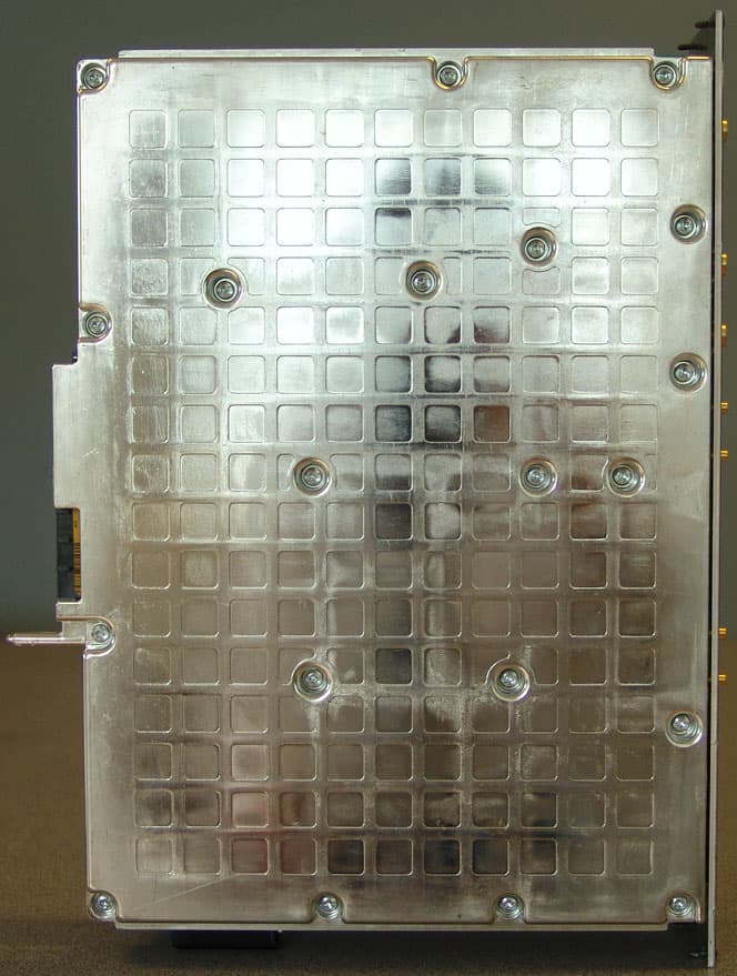
B5KEKRC1311004-2
Jun 13, 2007PCS Broadband GSM Base station transceiver
Equipment Class
PCB - PCS Licensed Transmitter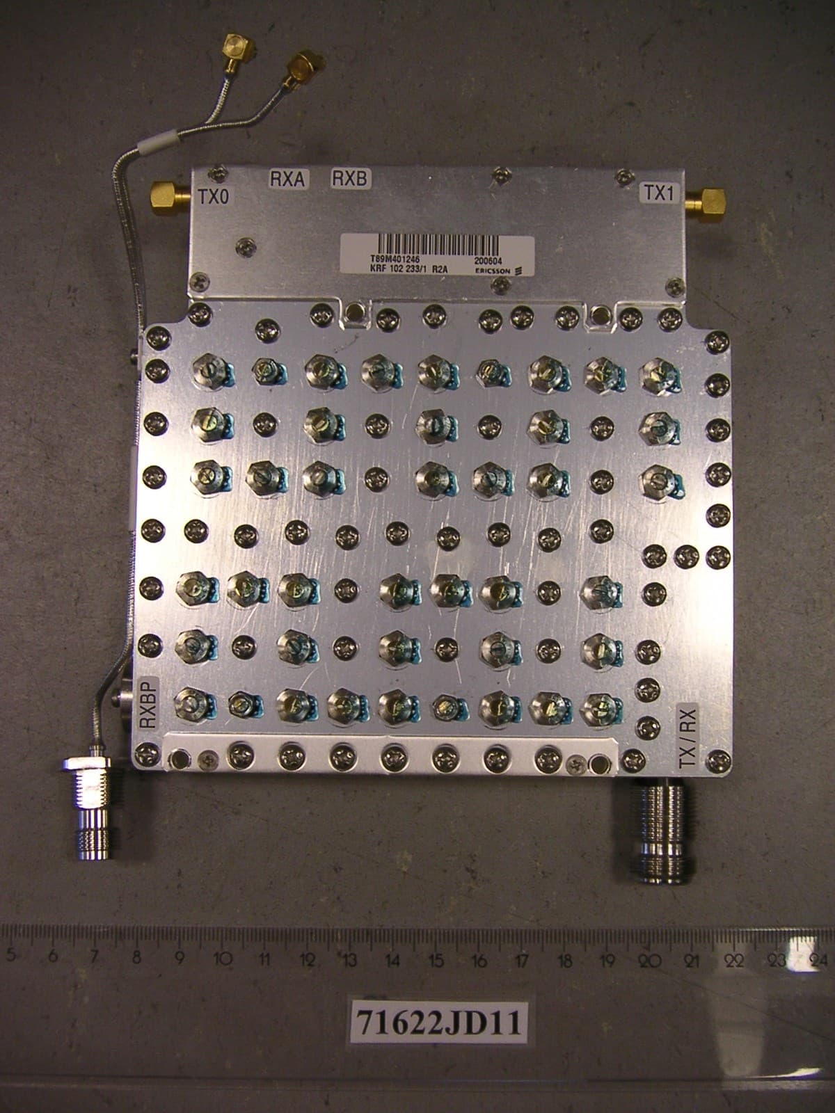
B5KCKRC16184-3
Sep 26, 2006PCS Broadband GSM Base station
Equipment Class
PCB - PCS Licensed Transmitter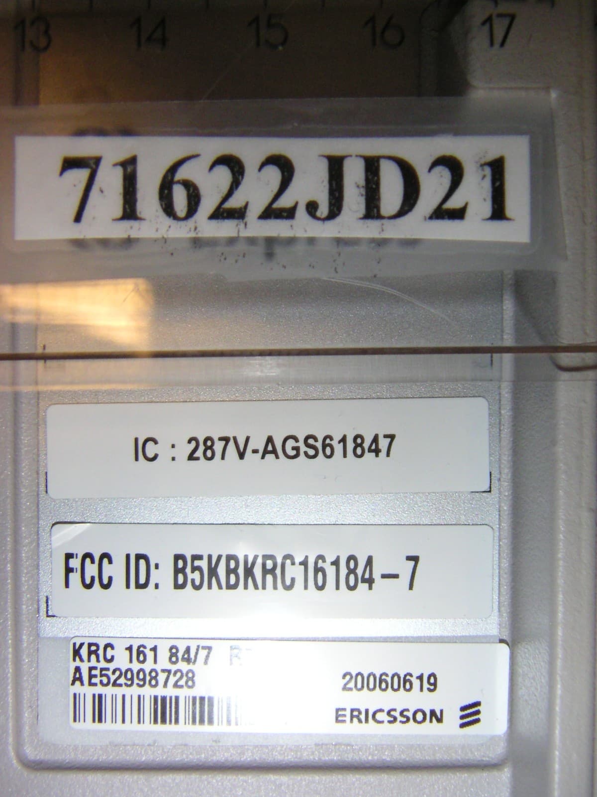
B5KCKRC16184-7
Sep 26, 2006PCS Broadband GSM Base station
Equipment Class
TNB - Licensed Non-Broadcast Station Transmitter
B5KDKRC1311005-2
Sep 06, 2006Broadband GSM Base station transceiver
Equipment Class
TNB - Licensed Non-Broadcast Station Transmitter
B5KAKRC1311013-2
Apr 04, 2005Broadband GSM Base station transceiver
Equipment Class
PCB - PCS Licensed Transmitter