B5KEKRC1311004-2PCS Broadband GSM Base station transceiver
Ericsson Radio Systems AB
Click to zoom
Application Details
- Equipment Class
- PCB - PCS Licensed Transmitter
- Date of Grant
- Jun 13, 2007
- Application Purpose
- Original Equipment
- Date of Application
- Jun 13, 2007
- Equipment Note
- PCS Broadband GSM Base station transceiver
- Frequency Range
- 1930.20000000 - 1989.80000000
- Company
- Ericsson Radio Systems AB
- Country
- Sweden
Documents & Files
Document Text
Text extracted from the exhibit documents filed with the FCC. Open a document above to read the original.
Cover Letter(s)
Open EXHIBIT 13 1 (2) Prepared (also subject responsible if other) No. EAB/FJG/VR Per Helmersson B5KEKRC1311004-2 Uen Approved Checked Date Rev Reference KI/EAB/FJG/VR (P Helmersson) 2007-06-08 A Federal Communications Commission Authorization & Evaluation Division 7435 Oakland Mills Road Columbia, Maryland 21046 Attention: Equipment Authorization Branch SP Sveriges Provnings- och ForskningsInstitut Brinellgatan 4 Box 857 S-501 15 Borås Sweden June 8, 2007 Subject: Certification for FCC ID: B5KEKRC1311004-2 Gentlemen; Ericsson AB requests a Grant of Certification (Type Acceptance) for the mentioned FCC Identifier above. This base station transceiver is designed for use in the GSM 1900 MHz cellular telephone system. The transmitter will operate from 1930.2 to 1989.8 MHz. The receiver circuit supports 1850.2 to 1809.8 MHz. The base station operates in the 1900 MHz broadband PCS services as per 47 CFR Part 24 subpart E. It meets the requirements of GSM1900 11.10-1 version 4.19.1 specification for operation in GSM cellular systems. The transceiver can be used in the base station models RBS 2106, RBS 2106V3 RBS 2107, RBS 2206, RBS 2206V2 and RBS 2207. These base stations will in normal mode operate at a nominal power out of 45 dBm for GMSK and 41 dBm for 8- PSK at the antenna connector when using combiner unit CDU-G, CDU-J or CDU-K and 41 dBm for GMSK and 38 dBm for 8-PSK when using CDU-F. In TCC mode with two transmitters combined on the same frequency the nominal output power is 46 dBm for GMSK and 44 dBm for 8-PSK. TCC can only be used together with CDU-G, CDU-J and CDU-K. The power output is reducible to ~0.3 watts . Due to the too wide frequency spectrum at the band edges the output power has to be reduced. With CDU-G, CDU-F, CDU-J and CDU-K in both GMSK and 8-PSK mode the output power in channel 512 – 1930.2 MHz and channel 810 – 1989.8 MHz has to be reduced to a maximum of 37 dBm. The power reduction is done by database settings in the switch software and is a part of the cell planning by the operator. Ericsson AB requests confidentiality under CFR 0.459. Confidentiality for the following exhibits is requested: Exhibit 4 Block diagram Exhibit 5 Part 1 Schematics Exhibit 5 Part 2 Schematics Exhibit 8 Internal manuals Exhibit 9 Internal photos Exhibit 12 Circuit description The Radio Base Station (RBS) is always installed and placed in an area with access only to authorize personal. Sensitive information, such as internal photos and manuals is not available for general public in any form. Only customer with a Non-Disclosure Agreement (NDA) in place will get access to sensitive information. So the only way a competitor could get technical information on the RBS is from FCC records. Justification of this request is in order to protect the large investment in developing this technology and to facilitate the circuit miniaturization utilized in this design and protect the innovative design as well as proprietary techniques which are implemented. In order to protect Ericsson’s competitive advantage on these proprietary techniques, we request the above listed exhibits be held as confidential and withheld from the Public Information File. We further certify that the applicant nor any party to the application is subject to a denial of Federal benefits, that includes FCC benefits, pursuant to section 5301 of the Anti-Drug abuse Act of 1988, 21 U.S.C. Section 862. Open EXHIBIT 13 2 (2) Prepared (also subject responsible if other) No. EAB/FJG/VR Per Helmersson B5KEKRC1311004-2 Uen Approved Checked Date Rev Reference KI/EAB/FJG/VR (P Helmersson) 2007-06-08 A Ericsson AB accept by this request the agreement set out in the document "Bilaga SPCR 125 -Avtal om marknadskontroll för radioutrustning certifierad för USA-marknaden" If additional information is needed, please contact me on the below listed number. Sincerely, Per Helmersson Staff Engineer, Regulatory Programs Ericsson AB Torshamnsgatan 21-23 (Färögatan 6) Kista, SE-164 80 Stockholm Sweden Telephone No.: +46 8 764 16 52 Fax No.: +46 8 404 41 90 e-mail [email protected]
External Photos
Date Page KRC 131 1004/2 R4A 2007-05-28 1(3) External photos Front side Rear side Date Page KRC 131 1004/2 R4A 2007-05-28 2(3) External photos Left side Date Page KRC 131 1004/2 R4A 2007-05-28 3(3) External photos Right side
ID Label/Location Info
Date Page KRC 131 1004/2 R4A 2007-05-28 1(1) FCC ID FCC ID label and placement
Test Report
Date Reference Page REPORT 2007-05-23 F703077-F24 2 (2) Table of contents Description of the test object Appendix 1 Operation mode during measurements Appendix 1 Purpose of test Appendix 1 Test setups Appendix 1 RF power output Appendix 2 Occupied bandwidth Appendix 3 Band edge Appendix 4 Spurious emission at antenna terminals Appendix 5 Field strength of spurious radiation Appendix 6 Frequency stability Appendix 7 Hardware list and software Appendix 8 Photos Appendix 9 Date Reference Page REPORT FCC ID: B5KEKRC1311004-2 2007-05-23 F703077-F24 1 (3) Appendix 1 Description - Equipment Under Test (EUT) Equipment: GSM Base station transceiver 1900 MHz Tx Frequency range: 1930.2-1989.8 MHz Modulations: GMSK and 8-PSK Nominal power voltage: 24 V DC Tested Channels Radiated measurements: CDU-F All six dTRUs were activated at maximum output power with the following settings: dTRU TRX Modulation ARFCN RF config. 1 0 GMSK 512 Uncombined 1 8-PSK 542 Uncombined 2 2 GMSK 572 Uncombined 3 8-PSK 602 Uncombined 3 4 GMSK 631 Uncombined 5 8-PSK 661 Uncombined 4 6 GMSK 685 Uncombined 7 8-PSK 710 Uncombined 5 8 GMSK 735 Uncombined 9 8-PSK 760 Uncombined 6 10 GMSK 785 Uncombined 11 8-PSK 810 Uncombined CDU-K Five dTRUs were activated at maximum output power with the following settings: dTRU TRX Modulation ARFCN RF config 1 0 GMSK 512 Combined 1 8-PSK 537 Combined 2 2 GMSK (TCC) 710 Combined TCC 3 - - - 3 4 8-PSK 652 Combined 5 GMSK 587 Combined 4 6 8-PSK (TCC) 661 Combined TCC 7 - - - 5 8 GMSK 785 Uncombined 9 8-PSK 810 Uncombined The radiated spurious emission measurements were done with the three RF configurations listed above at the same time as worst case configuration. The radiated measurements were performed with the EUT installed in a RBS 2206V2 which was used as a worst case configuration. Date Reference Page REPORT FCC ID: B5KEKRC1311004-2 2007-05-23 F703077-F24 2 (3) Appendix 1 Conducted measurements: ARFCN Frequency 512 1930.2 513 1930.4 537 1935.2 562 1940.2 661 1960.0 760 1979.8 785 1984.8 809 1989.6 810 1989.8 All RF conducted measurements were performed with the EUT installed in a RBS 2206V2 powered with DC power (the list of the RBS hardware is shown in appendix 8). The measurements were done at the output connector of CDU-K (BFL 119 447/1 rev. R1A) with serial number TR45478203. The dTRU with serial number AE54185936 was used for the measurements. The CDU-F (BFL 119 156/1 rev. R2B) with serial number A400206745 were used for the measurements with CDU-F. The dTRUs with serial number AE54185951, AE54185952, and AE54185938 were used for the measurements with CDU-F. The measurements were performed with configurations that represents worst case scenario. Manufacturer’s representative Per Helmersson, Ericsson AB Purpose of test The purpose of the tests is to verify compliance to the performance characteristics specified in FCC CFR47. References Measurements were done according to relevant parts of the following standards: ANSI/TIA/EIA-603-C-2004 J-STD007A Vol 1 ANSI/TIA/EIA 136-280-D-2002 Reservation The test results in this report apply only to the particular Equipment Under Test (EUT) as declared in the report. Delivery of test object The test object was delivered: 2007-04-27 Test engineers Jörgen Wassholm, Stefan Larsson, Fredrik G Isaksson and Jonas Bremholt Test witnesses Lars Hagbjörk, Annika Szalkai, and Mikael Ohlsson, Ericsson AB Date Reference Page REPORT FCC ID: B5KEKRC1311004-2 2007-05-23 F703077-F24 3 (3) Appendix 1 Test set-up 1. Computer, with software RBSMMI ver. R10A07 2. Ericsson RBS Master 2 LPY 107 1007/1 R1F/A 3. 6 Dummy loads (50 ohm) Interfaces: Type of port: Power: 120 VAC, 60 Hz AC mains Power: 24 VDC DC power Antenna: Coaxial cable 50 ohm Antenna G703: T1, shielded multi-wire with 15-pin D-sub connector Telecom TG-sync: Shielded multi-wire, unterminted Signal Alarm: Unshielded multi-wire, terminated in distribution frame Signal GPS: Shielded multi-wire, 9-pin DSUB, unterminated Signal EPC: Shielded multi-wire Signal Date Reference Page REPORT FCC ID: B5KEKRC1311004-2 2007-05-23 F703077-F24 1 (4) Appendix 2 RF Power output measurements according to CFR 47 2.1046 Date 2007-05-02 2007-05-04 Temperature 23 °C ± 3 °C 22 °C ± 3 °C Humidity 22 % ± 5 % 35 % ± 5 % Test set-up and procedure Measurements were made at CDU-K and CDU-F output connectors. The output was connected to a Peak power analyser via a 50 ohm attenuator. The transmitter was modulated with pseudorandom data and with maximum power in all the time slots during the measurements. Measurement equipment Calibration Due SP number Boonton RF Peak power meter/analyzer 2007-08 503 144 Boonton Power sensor 56518-S/4 2008-02 503 145 Multimeter Fluke 87 2007-11 502 190 Testo 610, Temperature and humidity meter 2008-04 502 658 Measurement uncertainty: 0.5 dB Results Modulation: GMSK dTRU, output 1+2, with internal combiner plus TCC. Maximum rated output power level after CDU-K: 46 dBm Test conditions Transmitter power (dBm) Peak/ RMS Channel 512 Channel 661 Channel 810 T nom 22 °C V nom 24 V DC 47.0/ 46.1 47.4/ 46.4 47.0/ 46.1 dTRU, output 1, without internal combiner: Maximum rated output power level after CDU-K: 45 dBm Test conditions Transmitter power (dBm) Peak/ RMS Channel 512 Channel 661 Channel 810 T nom 22 °C V nom 24 V DC 44.6/ 43.8 45.1/ 44.2 44.6/ 43.8 dTRU, output 2, without internal combiner: Maximum rated output power level after CDU-K: 45 dBm Test conditions Transmitter power (dBm) Peak/ RMS Channel 512 Channel 661 Channel 810 T nom 22 °C V nom 24 V DC 44.8/ 43.9 45.2/ 44.3 44.8/ 43.9 Date Reference Page REPORT FCC ID: B5KEKRC1311004-2 2007-05-23 F703077-F24 2 (4) Appendix 2 dTRU, output 1, with internal combiner: Maximum rated output power level after CDU-K: 40 dBm Test conditions Transmitter power (dBm) Peak/ RMS Channel 512 Channel 661 Channel 810 T nom 22 °C V nom 24 V DC 40.9/ 40.1 41.2/ 40.5 40.9/ 40.2 dTRU, output 2, with internal combiner: Maximum rated output power level after CDU-K: 40 dBm Test condit…
Text truncated - open the document above for the full version.
Contact Information
Applicant
Bo Bergstrom(Manager)
+468 757 0401Fax: +468 751 4687
Technical Contact
Test Firm
SP Technical Research Institute of SwedenMagnus Winehem
Technical Specifications
| # | Rule Parts | Frequency Range | Power Output | Emission | Tolerance |
|---|---|---|---|---|---|
| 4 | 24E | 1.93 GHz - 1.99 GHz | 25 W | 240KG7W | 0.05 ppm |
Other Applications from Ericsson Radio Systems AB
B5KCKRC16184-3
Sep 26, 2006PCS Broadband GSM Base station
Equipment Class
PCB - PCS Licensed Transmitter
B5KCKRC16184-7
Sep 26, 2006PCS Broadband GSM Base station
Equipment Class
TNB - Licensed Non-Broadcast Station Transmitter
B5KDKRC1311005-2
Sep 06, 2006Broadband GSM Base station transceiver
Equipment Class
TNB - Licensed Non-Broadcast Station Transmitter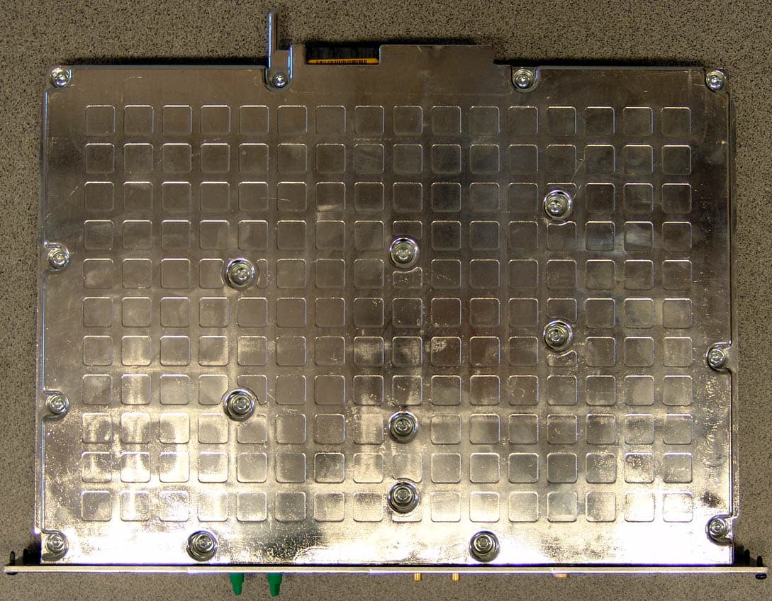
B5KAKRC1311013-2
Apr 04, 2005Broadband GSM Base station transceiver
Equipment Class
PCB - PCS Licensed Transmitter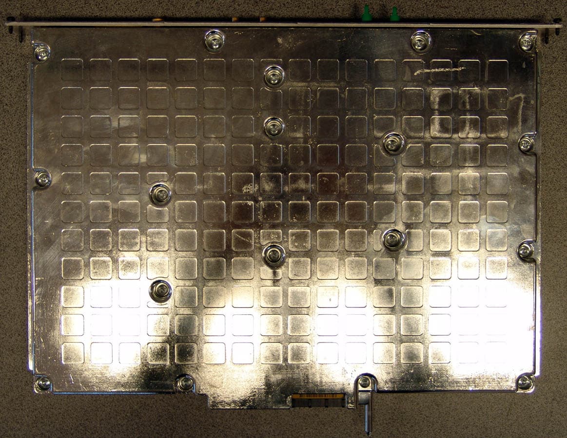
B5KAKRC1311010-2
Apr 04, 2005Broadband GSM Base station transceiver
Equipment Class
TNB - Licensed Non-Broadcast Station Transmitter