B5KKRC12110-21Cellular AMPS/DAMPS Base Station
Ericsson Radio Systems AB
Click to zoom
Application Details
- Equipment Class
- TNB - Licensed Non-Broadcast Station Transmitter
- Date of Grant
- Jan 17, 2000
- Application Purpose
- Original Equipment
- Date of Application
- Oct 25, 1999
- Equipment Note
- Cellular AMPS/DAMPS Base Station
- Frequency Range
- 869.00000000 - 894.00000000
- Company
- Ericsson Radio Systems AB
- Country
- Sweden
Documents & Files
Document Text
Text extracted from the exhibit documents filed with the FCC. Open a document above to read the original.
Users Manual
EXHIBIT 8 Page 1 APPLICANT: Ericsson Radio System AB FCC ID NO. B5KKRC12110-21 EXHIBIT 8 - COVER SHEET Table of Contents RBS884 Base Station Hardware Technical Description 36 pages Description RBS 884 27 pages Line Interface Board Description 24 pages Description1 (36) ERA/AR/SL GFO1996-08-02C8/1551-ANT 244 01 Uen ERA/AR/SL (S Hellmark)CMS88 Uppgjord —PreparedDatum —DateRevDokumentnr —Document no Godkänd —ApprovedKontr —CheckedTillhör/referens —File/reference E DQI status: EXITED - Estimated remaining major error/page: 6.5 RBS884 Base Station Hardware Technical Description Abstract This document describes the macro base station for the 800 MHz band pro- vided by the RBS884 platform. It describes the hardware structure with focus on system level to give an overview of the fundamental parts and structures. More details can be found in supplementary documents. The document shall be used as a supplement to the description of the MBS subsystem for under- standing of the RBS884 base station concept. The acronym RBS884 alone is the generic name of the macro base station for 800 MHz. Application Introduction of customers and Ericsson personnel to RBS884 HW. Supplementary documents [1] Description of MBS, 1551-ANT 244 01 [2] 1551-COA 109 294, Control Part [3] 1551-COA 109 295, Modem Par [4] 1551-COA 109 296, Antenna Near Part [5] 1551-COA 109 298, Support Part [6] LZB 119 722, Equipment Practice ContentsPage 1Revision Information3 2Introduction4 3Features5 4Limitations5 5Base station structure6 6Functional submodules and units7 7EMC and grounding principles8 8Environmental and safety10 9Basic fault handling and indications10 Description2 (36) 1996-08-02C8/1551-ANT 244 01 Uen Datum —DateRevDokumentnr —Document no E 10Base station interfaces13 11The control structure16 12The RF structure17 13Synchronization18 14Power supply and power distribution20 15Redundancy structure21 16CO-siting25 17Capacity26 18HW support for Traffic functions30 19HW support for Standard O&M functions31 20HW support for Optional O&M functions32 21References33 22Vocabulary34 Description3 (36) 1996-08-02C8/1551-ANT 244 01 Uen Datum —DateRevDokumentnr —Document no E 1Revision Information PB2-3Second non-reviewed version based on Rev A and following the guidelines outlined in AR/BU-94137 rev A. PB3->BUpdated in accordance with 63/1776-5/FCP&rbl103&rbl553 B->PC150W added PCx->CUpdated and approved in accordance with AR/S-96:061 Description4 (36) 1996-08-02C8/1551-ANT 244 01 Uen Datum —DateRevDokumentnr —Document no E 2Introduction The RBS884 base station is divided into well defined functional parts named COP, MOP, ANP and SUP. The intention is to make it possible to reuse parts of the system for developments concerning other systems and to perform independent improvements of the defined areas. COPMOPANP MSC rbs884macro SUP Transmission Network NINI Rx Rx Tx BS ETC STCRP GS RP CP #9/16 TRA RP NI T1 or E1 connection Figure 1RBS884 HW block diagram The RBS884 supports transcoder location in MSC only, which improves the transmission capacity by a factor three. The RBS884 is a fully multimode i.e. has all channel functions: - Digital Traffic Channel, DTC - Digital VERification, DVER - Control Channel, CC - Analog Voice Channel, AVC - Signal strength Receiver, SR - Digital Control CHannel, DCCH All carriers on a site are prepared to be TDMA frame and slot synchronized. The RBS884 platform utilizes equipment practice BYB 401 001. Description5 (36) 1996-08-02C8/1551-ANT 244 01 Uen Datum —DateRevDokumentnr —Document no E 3Features The RBS884 is designed for medium to high output power per carrier. 10 W transceivers or 30 W transceivers or 50 W transceivers can be selected. The RBS884 can be configured as an omni site, a two sector site or a three sector site. The RBS884 supports various cell patterns 7/21 and 4/12. The RBS884 highly scalable and its physical size depends on the maximum output power per carrier, the numbers of sectors and the number of carriers per sector. As an option the RBS884 can be equipped with a Tower Mounted Amplifier to balance the uplink RF-path and the downlink RF-path to increase coverage. 4Limitations The following functions and features are prepared in hardware, but will not have system support software-wise: - Analog verification (= AVC) in dual-mode verification - Control outputs - SW and HW information - Fault signal filtering - Pin pointing of faulty unit / Error log - RSSI calibration - RF test loop - Statistical supervision of DTC - APT-alarm for faulty RFTL - APT-alarm for faulty ALM (non-existant in this package) - Setting of MCU attenuation value per RCG (not needed on CMS88-markets) The RBS884 is not prepared for: - ADPCM/PCM transcoding in analog mode - BS power regulation dynamically (e.g. per time slot) The RBS884 also have the following limitations: - Cannot be used as a HUB to connect subordinated BSs to the MSC - Cannot be cascaded - Has no integrated power rectifiers - Has no unit generating the Air Frame Sync (AFS) Description6 (36) 1996-08-02C8/1551-ANT 244 01 Uen Datum —DateRevDokumentnr —Document no E 5Base station structure The base station consists of the following major functional parts: MSC rbs884macro1 ETB STR #9/16 EMRP TRX Rx Rx Tx PS MC COMB T S W COPMOPANP AC/DCBAT SUP DC distribution AC Mains Control paths Radio Frequency paths Voice & Data paths Figure 2The RBS884 structure COP - Control part Handles the communication with MSC and hosts the hardware for radio traffic control, statistics and control of MOP and ANP The COP is the SW-loadable part of the base station. For more information refer to Supplementary Documents [2]. MOP - Modem part Serves as the converter from speech and digital information into radio waves and vice versa. Hosts channel codec function and performs measurements on radio transmission quality. MOP consists of non-loadable HW. However, the TRX program memory can be changed from MSC by command, for correction purpose. The transcoder, TRA, is logically part …
Text truncated - open the document above for the full version.
Attestation Statements
EXHIBIT 2 APPLICANT: Ericsson Radio System ABFCC ID NO. B5KKRC12110-21 COMPLIANCE STATEMENT / CERTIFICATION OF DATA 2.911(d)The FCC ID: B5KKRC12110-21 transceiver with 11 W RF Module complies with the requirements specified in Office of Engineering and Technology Bulletin 53 2.911(d)The technical data contained in this application has been taken personally or under my supervision and is certified true and correct. My qualifica- tions are: Teletechnical Engineer ÅSÖ Gymnasium, Stockholm, Swede, 1975. Two years military experience with radar, communications and misssile equipment. Nine years experience in Electrical safety certifica- tions and five years in Electromagnetical Inter- ference certifications at SEMKO AB, the Swedish laboratory corresponding to Underwriters Labora- tories. Nine year experience with Cellular and Personal Communications System Base Stations at Ericsson Radio Systems AB, Stockholm, Sweden. NAME:______________________________ _Larry Lindström______________ POSITION:Engineer Regulatory Services__ Radio and EMC_________________ DATE:_14-10-1999___________________
Attestation Statements
EXHIBIT11 APPLICANT: Ericsson Radio System ABFCC ID NO. B5KKRC12110-21 RF EXPOSURE STATEMENT OF COMPLIANCE I hereby certify that the Ericsson Radio System AB manufactured KRC 121 10/2 with FCC ID: B5KKRC12110-21 was tested in accordance with ANSI/IEEE C95.1-1992 and was found to be compliant to the FCC ́srequirements for Maximum Personal Exposure (MPE). NAME:______________________________ _Larry Lindström______________ POSITION:Engineer Regulatory Services__ Radio and EMC_________________ DATE:_14-10-1999___________________
Block Diagram
EXHIBIT 4 APPLICANT: Ericsson Radio System AB FCC ID NO. B5KKRC12110-21 EXHIBIT 4 - COVER SHEET Table of Contents Block Diagram 1911-ROA 117 2046/14 Ux 1 page Block Diagram 1911-ROZ 104 03 Ux 1 page
Cover Letter(s)
Ericssonl October 26,1999 Federal Communications Commission Authorization & Evaluation Division 7435 Oakland Mills Road Columbia, Maryland 21046 Attention: Equipment Authorization Branch Subject: Certification for FCC ID: B5KKRC12110-21 Gentlemen, Ericsson Radio Systems AB.requests a grant of Certification (Type Acceptance) for the above mentioned FCC Identifier. This dual mode cellular base station is for use in the 800 MHz Domestic Public Cellular Radiotelephone Communications Services, Subpart H of Part 22, and was tested using TIA/IS-136/IS-138 for operation in Cellular Systems. This base station will operate in either the analogue or digital mode at a maximum power out of 11 watts at the antenna connector of the TRX unit. The statement concerning MPE compliance for this base station is contained in exhibit 11. Ericsson Radio Systems AB requests confidentiality under CFR 0.459. Confidentiality for the following exhibit is requested Exhibit 5........Circuit Diagrams Justification of this request is in order to protect the large investment in developing this technology and to facilitate the circuit miniaturization utilized in this design and protect the innovative design as well as proprietary techniques which are implemented. In order to protect Ericsson’s competitive advantage on these proprietary techniques, we request the above listed exhibits be held as confidential and withheld from the Public Information File. If additional information is needed, please contact me on the below listed number. Sincerely, Larry L. Roberts Staff Engineer, Regulatory Programs Telephone No.: (804) 592-7732 Fax No.: (804) 592-6510 e-mail No. [email protected]
External Photos
EXHIBIT 3 Page 3.1 APPLICANT: Ericsson Radio System AB FCC ID NO. B5KKRC12110-21 EXTERNAL PHOTOGRAPHS 2.1033 (c)(12) Front of RBS884 Macro with doors of. EXHIBIT 3 Page 3.2 APPLICANT: Ericsson Radio System AB FCC ID NO. B5KKRC12110-21 EXTERNAL PHOTOGRAPHS 2.1033 (c)(12) Front of RBS884 Macro with doors on. EXHIBIT3 Page3.3 APPLICANT: Ericsson Radio System ABFCC ID NO. B5KKRC12110-21 EXTERNAL PHOTOGRAPHS 2.1033(c)(12)Front CASSETTE for RBS882 EXHIBIT3 Page3.4 APPLICANT: Ericsson Radio System ABFCC ID NO. B5KKRC12110-21 EXTERNAL PHOTOGRAPHS 2.1033(c)(12)Front of MINIMDBS with AC Supply
ID Label/Location Info
EXHIBIT1 Page 1.1 APPLICANT: Ericsson Radio System ABFCC ID NO. B5KKRC12110-21 IDENTIFICATION PLATE 2.1033(c)(11)ID Label EXHIBIT1 Page1.2 APPLICANT: Ericsson Radio System ABFCC ID NO. B5KKRC12110-21 IDENTIFICATION PLATE 2.1033(c)(11)ID Label Location
Internal Photos
EXHIBIT9 Page9.1 APPLICANT: Ericsson Radio System ABFCC ID NO. B5KKRC12110-21 INTERNAL PHOTOGRAPHS 2.1033(c)(12)Lid Outside plus Front EXHIBIT9 Page9.2 APPLICANT: Ericsson Radio System ABFCC ID NO. B5KKRC12110-21 INTERNAL PHOTOGRAPHS 2.1033(c)(12)Component Side of Board under Lid EXHIBIT9 Page9.3 APPLICANT: Ericsson Radio System ABFCC ID NO. B5KKRC12110-21 INTERNAL PHOTOGRAPHS 2.1033(c)(12)Reverse side of Board EXHIBIT9 Page9.4 APPLICANT: Ericsson Radio System ABFCC ID NO. B5KKRC12110-21 INTERNAL PHOTOGRAPHS 2.1033(c)(12)Bottom Outside - Cooler
Operational Description
EXHIBIT12 Page12.0 APPLICANT: Ericsson Radio System ABFCC ID NO. B5KKRC12110-21 EXHIBIT 12 - COVER SHEET Table of Contents General Information12.1 Frequency Stabilizing Circuit 12.2 Spurious and harmonic suppression12.3 Limiting Power12.4 Digital and Analog Modulation12.5 EXHIBIT12 Page12.1 APPLICANT: Ericsson Radio System ABFCC ID NO. B5KKRC12110-21 DESCRIPTION 2.1033(c)(2)FCC Identifier:B5KKRC12110-21 This transmitter is only for use in the Domestic Cellular Radio Telephone Communica- tions Service, Subpart H of Part 22. The frequencies are generated using a phase- locked synthesizer. The synthesizer is locked to the in-coming sync signal from the PCM- link used for the system. (4)Type of Emission:40KOF1D 40KOF8W 30K0DXW 20KOFXW (5)Frequency range:869 to 894 MHz (6) Range of Operating Power: This transmitter is designated to supply 11 Watts of power at the antenna connector of the radio channel unit (TRX). 100 power levels are provided in 0.2 dB steps down to 110 milliwatts. (7)Maximum Power Rating: The maximum power rating under environmental supply voltage variations is equal to 11 watts plus the power level tolerance of + 1 dB. Therefore the maximum output power is 13.8 watts. (8)Final Amplifier Voltage and Current in normal operation (Rated power is for 1 device in the output stage). 0.11 Watts 11 Watts 24.5 V DC24.5 V DC 0.45 A DC2.4 A DC EXHIBIT12 Page12.2 APPLICANT: Ericsson Radio System ABFCC ID NO. B5KKRC12110-21 DESCRIPTION 2.1033(c)(10)Frequency Stabilizing Circuit Description The transmitter uses a phase-locked UHF VCO Operating between 761.07 MHz to 788.04 MHz. This signal is phase-locked to an internal 3.24 MHz reference oscillator frequency (RAREF) which in turn is divided down 6 times from the 19.44 MHz VCO in the digital block. The VCO is phase-locked to the incoming T- Link sync frequency of 2.048 MHz. RBS884 Macro and RBS882 Cassette The T-link is converted from a C-link in the DCON-board in the TCB-cabinet or in the cas- sette where the TRX:s are mounted. The C-link is phase-locked to the local PCM-link sync frequency of 1.544 MHz (or 2.048 MHz for non- US markets) in the CRI in the RBS884 Macro base station or the CRI in the RBS882 base station for cassettes. MINIMDBS The T-link is converted from a C-link in the MDCON-board in the MINIMDBS. The C-link is divided down 8 times from the local owen oscillator of 16.384 MHz in the PDB-board in the MINIMDBS. EXHIBIT12 Page12.3 APPLICANT: Ericsson Radio System ABFCC ID NO. B5KKRC12110-21 DESCRIPTION 2.1033(c)(10)Spurious and Harmonic Suppression Spurious and harmonic suppression is achieved by using a bandpass filter (N403 LX-stage) in the exciter amplifier and a passive bandpass filter connected to the TRX output. The output from the bandpass filter is connected to the applicable combiner system in the base station. The combiner system will connect all the TRX units in the RBS884 base station family to the same antenna output. The combiner system will connect all the cas- settes with TRX units, all existing TRM and DTRM units in the RBS882 base station family to the same antenna output. EXHIBIT12 Page12.4 APPLICANT: Ericsson Radio System ABFCC ID NO. B5KKRC12110-21 DESCRIPTION 2.1033(c)(10)Limiting Power The EMRPS function allows the RF power output to be set from 0 dB to – 20 dB attenuation in 0.2 dB steps from the MSC (Mobile Switching Center). The power levels can be in the range from a minimum of 110 milliwatts to a maximum Of 11 watts at the output of the TRX. The EMRPS supervises the feedback loop (RFF) from the Coupler stage to Linearization by checking the baseband signals. If the power output changes, the EMRPS will adjust the gain in the exciter amplifier. If some fault happens in the output power circuits, the EMRPS will compare the fault with prestored values and report the fault to the Switch via alarm codes in different levels. The highest alarm level is a serious fault and this alarm will get the EMRPS to shut down the output power stages without confirmation from the Switch. The EMRPS function will also control the RF power output according to the environment temperature. The power amplifier will not be able to get the supply current it need above 50 degrees C and below –5 degrees C. Then will the EMPRS shut down the power output since the unit is not able give a power out- put above –3 dB below set power level. EXHIBIT12 Page12.5 APPLICANT: Ericsson Radio System ABFCC ID NO. B5KKRC12110-21 DESCRIPTION 2.1033(c)(10)Digital Modulation The TRX is used both as voice channel and control channel in the RBS884 System. The modulation can be digital or analog. It can also be used as a data channel for Digital Packet Data. The DIGITAL modulation is limited in the waveform generator. The burst data from each time slot is formatted with syncwords and coded with a digital verification color code and user channel data. The formatted burst data are then converted to digital I and Q signals. These digital I and Q signals are then filtered in a square root raised cosine filter to form the correct modulation. The filtered signals are ten times oversampled and converted to analogue signals in a D/A- Converter. The modulation form is π/4-DQPSK for control and voice channel and GMSK for the CDPD channel. (10)Analog Modulation The TRX is used both as voice channel and control channel in the RBS884 System. The modulation can be digital or analog. It can also be used as a data channel for Digital Packet Data. The ANALOG modulation is limited in the wave- form generator. The speech or control data from the PCM-line is formatted as per IS-136 with syncwords and SAT. The formatted data are then converted to ”digital I and Q sig- nals” too form the correct frequency modula- tion. The signals are then ten times oversam- pled and converted to analogue signals in a D/A-Converter. The signals are converted in such a way that the output signal will format a Frequency Modulated signal.
Parts List/Tune Up Info
EXHIBIT10 Page10 APPLICANT: Ericsson Radio System ABFCC ID NO. B5KKRC12110-21 EXHIBIT 10 - COVER SHEET Table of Contents Function Block10.1 Function Block Cont.10.2 Function Block Cont.10.3 Function Block Cont.10.4 Tune-Up Procedure10.5 Power Tune-Up – Power Limiting10.6 EXHIBIT10 Page10.1 APPLICANT: Ericsson Radio System ABFCC ID NO. B5KKRC12110-21 FUNCTION OF ACTIVE CIRCUIT DEVICES 2.1033(c)(10)Function of Active Circuit Devices Function Block Digital Control (1911-ROZ 104 03) D18XLINEDRIVER TS D2PLD D4ASIC TRISTAN, CONTROL Radio & Synthesizer D6DSP, PLL- & PCM-link Control D8SRAM 64k16 D9FLASHROM 256k16 D100DSP, Receiver D101SRAM 64k16 D102ASIC ISOLET, RSSI Receiver, IfA- & IfB- Receiver D104DSP, Receiver D201FlipFlop P-edge Trigger D202Inverter D203D-type FlipFlop D204Inverter D206Inverter D300D-type FlipFlop N1Reset Circuit N100VCO 27.300 MHz N200ASIC ADDA, A/D-converter, D/A-converter N203Voltage Reference N204VCO 19.44 MHz N300Switch Regulator N301Switch Regulator V3Driver FlashROM VPP V4Driver FlashROM VPP V6LED Driver V8LED Driver V200Voltage Regulator V201Voltage Regulator V202Voltage Regulator V203Voltage Regulator V204Voltage Regulator V205Voltage Regulator EXHIBIT10 Page10.2 APPLICANT: Ericsson Radio System ABFCC ID NO. B5KKRC12110-21 FUNCTION OF ACTIVE CIRCUIT DEVICES 2.1033(c)(10)Function of Active Circuit Devices Function Block RXRF (1911-ROZ 104 04) N602ASIC ODEN, Downconverter T601Balun T621Balun T622Balun V650Voltage Regulator V651Voltage Regulator Function Block RXIF (1911-ROZ 104 05) N801ASIC FREJA, If Circuit N810BandPassFilter 62.94 MHz N820BandPassFilter 62.94 MHz N811BandPassFilter 455 kHz N821BandPassFilter 455 kHz T800Transformer V800Voltage Regulator V801Voltage Regulator Function Block IFLO (1911-ROZ 104 06 N700Voltage Regulator N701PLL Synthesizer N702PLL Synthesizer N750Voltage Regulator V703Amplifier V707Amplifier V710Voltage Regulator V711Voltage Regulator V712Voltage Regulator V753Amplifier V757Amplifier V760Voltage Regulator V761Voltage Regulator V762Voltage Regulator EXHIBIT10 Page10.3 APPLICANT: Ericsson Radio System ABFCC ID NO. B5KKRC12110-21 FUNCTION OF ACTIVE CIRCUIT DEVICES 2.1033(c)(10)Function of Active Circuit Devices Function Block FG (1911-ROZ 104 07) N903PLL Synthesizer N905Amplifier N907Oscillator 761 – 786 MHz V923Voltage Regulator V924Voltage Regulator V925Voltage Regulator Function Block LX (1911-ROZ 104 08) D401Inverter N401Differential Amplifier 4pcs N402ASIC GLEIPNER, Linearization N403Band Pass Filter N404Amplifier N407Voltage Regulator N408Voltage Regulator N409Voltage Reference N411ASIC RIO, Serial/Parallel Interface N415Amplifier N416Voltage Regulator T401Transformer T402Transformer T403Transformer T404Transformer V411VSWR Alarm Driver V412Voltage Regulator V413Voltage Regulator V420Power Setting Driver V421Power Setting Driver V422Power Setting Driver EXHIBIT10 Page10.4 APPLICANT: Ericsson Radio System ABFCC ID NO. B5KKRC12110-21 FUNCTION OF ACTIVE CIRCUIT DEVICES 2.1033(c)(10)Function of Active Circuit Devices Function Block TXPA (1911-ROZ 104 09) N503Direction Coupler N504Controllable Voltage Regulator N511Temperature Sensor V5011 st Amplifier V5022 nd Amplifier V511Bias V501 V512Bias V502 V514VSWR Alarm V515Driver Controllable Voltage Regulator EXHIBIT10 Page10.5 APPLICANT: Ericsson Radio System ABFCC ID NO. B5KKRC12110-21 TUNE-UP PROCEDURE 2.1033(c)(9)Tune-Up Procedure All the necessary adjustments will be set in the factory, and should need no adjustments out in the field (pre-tuned coils are used, etc.). If the TRX is not able to maintain the requirements for power output, frequency sta- bility, etc., the Switch will give an indi- cation that the TRX needs service. If it is a great failure, the EMRPS will shut down the TRX without confirmation from the Switch. EXHIBIT10 Page10.6 APPLICANT: Ericsson Radio System ABFCC ID NO. B5KKRC12110-21 CIRCUIT AND DEVICE DESCRIPTIONS 2.1033(c)(9,10)Power Tune-Up – Power Limiting The EMRPS function allows the RF power output to be set from 0 dB to – 20 dB attenuation in 0.2 dB steps from the MSC (Mobile Switching Center). The power levels can be in the range from a minimum of 110 milliwatts to a maximum of 11 watts at the output of the TRX. The EMRPS supervises the feedback loop (RFF) From the Coupler stage to Linearization by checking the baseband signals. If the power output changes, the EMRPS will adjust the gain in the exciter amplifier. If some fault happens in the output power circuits, the EMRPS will compare the fault with prestored values and report the fault to the Switch via alarm codes in different levels. The highest alarm level is a serious fault and this alarm will get the EMRPS to shut down the output power stages without confirmation from the Switch.
Test Report
EXHIBIT6 Page6.01 APPLICANT: Ericsson Radio System ABFCC ID NO. B5KKRC12110-21 EXHIBIT 6 – COVER SHEET Table of Contents EXHIBIT 6 – COVER SHEET6.01 EXHIBIT 6 – COVER SHEET CONTINUED6.02 EXHIBIT 6 – COVER SHEET CONTINUED6.03 RF POWER OUTPUT Method and Equipment6.04 Analog Mode High Power Channel 3846.05 High Power Channel 7996.06 High Power Channel 9916.07 Digital Mode High Power Channel 3846.08 High Power Channel 7996.09 High Power Channel 9916.10 MODULATION CHARACTERISTICS Analog Mode SAT6.11 Wideband Data6.12 Audio Modulating Circuit Compressor Disabled6.13 Compressor Enabled6.14 Modulation Limiting Method and Equipment6.15 SAT Off6.16 Frequency Response Audio Low Pass Filtering6.17 Digital mode6.18 Data Packet mode6.19 EXHIBIT6 Page6.02 APPLICANT: Ericsson Radio System ABFCC ID NO. B5KKRC12110-21 EXHIBIT 6 – COVER SHEET CONTINUED Table of Contents OCCUPIED BANDWIDTH Method and Equipment6.20 Analog Mode Continouos mode Span 90 kHz6.21 Voice Modulation with SAT Span 90 kHz6.22 Span 200 kHz6.23 Wideband Data Span 90 kHz6.24 Span 200 kHz6.25 Digital Mode Span 90 kHz6.26 Span 200 kHz6.27 Data Packet Mode Span 90 kHz6.28 Span 180 kHz6.29 CONDUCTED SPURIOUS MISSIONS Method and Equipment6.30 Analog Mode Channel 9916.31 Channel 3846.32 Channel 7996.33 Channel 799 with bandpass6.34 Digital Mode Channel 9916.35 Channel 3846.36 Channel 7996.37 Channel 799 with bandpass6.38 EXHIBIT6 Page6.03 APPLICANT: Ericsson Radio System ABFCC ID NO. B5KKRC12110-21 EXHIBIT 6 – COVER SHEET CONTINUED Table of Contents RADIATED SPURIOUS EMISSIONS Methode and Equipment6.39 Analog Mode MACRO Channel 9916.40 Channel 7996.41 Digital Mode MACRO Channel 9916.42 Channel 7996.43 Analog Mode CASSETTE Channel 9916.44 Channel 7996.45 Digital Mode CASSETTE Channel 9916.46 Channel 7996.47 Data Packet Mode MINIMDBS Channel 9916.48 Channel 7996.49 FREQUENCY STABILITY Method and Equipment6.50 MACRO with CRI Supply Voltage 27.20 V6.51 Supply Voltage 23.12 V6.52 Supply Voltage 31.28 V6.53 CASSETTE with CRI Supply Voltage 27.20 V6.54 Supply Voltage 23.12 V6.55 Supply Voltage 31.28 V6.56 Data Packet MINIMDBS Method and Equipment6.57 Supply Voltage 115.0 V6.58 Supply Voltage 97.75 V6.59 Supply Voltage 132.3 V6.60 EXHIBIT6 Page6.04 APPLICANT: Ericsson Radio System ABFCC ID NO. B5KKRC12110-21 RF POWER OUTPUT ANALOG MODE 2.1046(a)RF Power Output The RF power output at the output terminal is plotted against supply voltage variation. The measurement was made per TIA/IS-136/ IS-138 using the following Equipment. Radio frequency 50 ohm load attached to the output. The power was measured on a BONTOON RF Peak power meter/analyzer. EXHIBIT6 Page6.05 APPLICANT: Ericsson Radio System ABFCC ID NO. B5KKRC12110-21 RF POWER OUTPUT ANALOG MODE 2.1046(a)RF Power Output Channel 384Output Power 40.4 dBm EXHIBIT6 Page6.06 APPLICANT: Ericsson Radio System ABFCC ID NO. B5KKRC12110-21 RF POWER OUTPUT ANALOG MODE 2.1046(a)RF Power Output Channel 799Output Power 40.4 dBm EXHIBIT6 Page6.07 APPLICANT: Ericsson Radio System ABFCC ID NO. B5KKRC12110-21 RF POWER OUTPUT ANALOG MODE 2.1046(a)RF Power Output Channel 991Output Power 40.4 dBm EXHIBIT6 Page6.08 APPLICANT: Ericsson Radio System ABFCC ID NO. B5KKRC12110-21 RF POWER OUTPUT DIGITAL MODE 2.1046(a)RF Power Output Channel 384Output Power 40.4 dBm EXHIBIT6 Page6.09 APPLICANT: Ericsson Radio System ABFCC ID NO. B5KKRC12110-21 RF POWER OUTPUT DIGITAL MODE 2.1046(a)RF Power Output Channel 799Output Power 40.4 dBm EXHIBIT6 Page6.10 APPLICANT: Ericsson Radio System ABFCC ID NO. B5KKRC12110-21 RF POWER OUTPUT DIGITAL MODE 2.1046(a)RF Power Output Channel 991Output Power 40.4 dBm EXHIBIT6 Page6.11 APPLICANT: Ericsson Radio System ABFCC ID NO. B5KKRC12110-21 MODULATION CHARACTERISTICS ANALOG MODE 2.1047(b)Modulation Characteristics SAT Freq.Output PowerPeak Deviation Chan.(MHz)(Watts)(+/- kHz) 384881.5211.02.14/2.12 799893.9711.02.13/2.14 991869.0411.02.14/2.14 The measurement was made per TIA/IS-136/ IS-138 using the following Equipment. The input signal source was R&S CMTA 54 Radiocommunication analyzer. The input signal was fed through a custom made audio-PCM-converter named Claudio. Radio frequency load 50 ohm attached to the output. The peak deviation was measured on a Rohde & Schwarz CMTA 54, Radiocommunication analyzer. EXHIBIT6 Page6.12 APPLICANT: Ericsson Radio System ABFCC ID NO. B5KKRC12110-21 MODULATION CHARACTERISTICS ANALOG MODE 2.1047(b)Modulation Characteristics Wideband Data Freq.Output PowerPeak Deviation Chan.(MHz)(Watts)(+/- kHz) 384881.5211.08.11/8.19 799893.9711.08.11/8.17 991869.0411.08.15/8.13 The measurement was made per TIA/IS-136/ IS-138 using the following Equipment. The input signal source was R&S CMTA 54 Radiocommunication analyzer. The input signal was fed through a custom made audio-PCM-converter named Claudio. Radio frequency load 50 ohm attached to the output. The peak deviation was measured on a Rohde & Schwarz CMTA 54, Radiocommunication analyzer. EXHIBIT6 Page6.13 APPLICANT: Ericsson Radio System ABFCC ID NO. B5KKRC12110-21 MODULATION CHARACTERISTICS ANALOG MODE 2.1047(a,b)Modulation Characteristics Audio Modulating Circuit The measurement was made per TIA/IS-136/ IS-138 using the following Equipment. The input signal source was R&S CMTA 54 Radiocommunication analyzer. The input signal was fed through a custom made audio-PCM-converter named Claudio. Radio frequency load 50 ohm attached to the output. The peak deviation was measured on a Rohde & Schwarz CMTA 54, Radiocommunication analyzer. Note: In the RBS884 and RBS882 systems it is not possible for the TRX to operate without the compressor enabled. EXHIBIT6 Page6.14 APPLICANT: Ericsson Radio System ABFCC ID NO. B5KKRC12110-21 MODULATION CHARACTERISTICS ANALOG MODE 2.1047(a,b)Modulation Characteristics Audio Modulating Circuit The measurement was made per TIA/IS-136/ IS-138 using the following Equipment. The input signal source was R&S CMTA 54 Radiocommunication analyzer. The input signal was fed through a custom made audio-PCM-con…
Text truncated - open the document above for the full version.
Contact Information
Applicant
Bo Bergstrom(Manager)
+468 757 0401Fax: +468 751 4687
Technical Contact
Ericsson Radio Systems ABLarry B Lindstrom
[email protected]+468 764 1273
Torshamnsgatan 21-23 · S-164 80 Stockholm · Sweden
Non-Technical Contact
Ericsson Inc.Larry L Roberts
[email protected]804 592 7732
Technical Specifications
| # | Rule Parts | Frequency Range | Power Output | Emission | Tolerance |
|---|---|---|---|---|---|
| 4 | 22.901(d) | 869 MHz - 894 MHz | 11 W | 20K0FXW | 0.25 ppm |
Other Applications from Ericsson Radio Systems AB
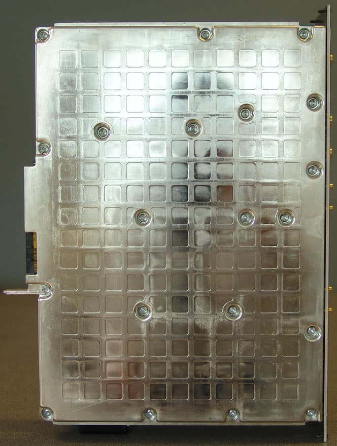
B5KEKRC1311004-2
Jun 13, 2007PCS Broadband GSM Base station transceiver
Equipment Class
PCB - PCS Licensed Transmitter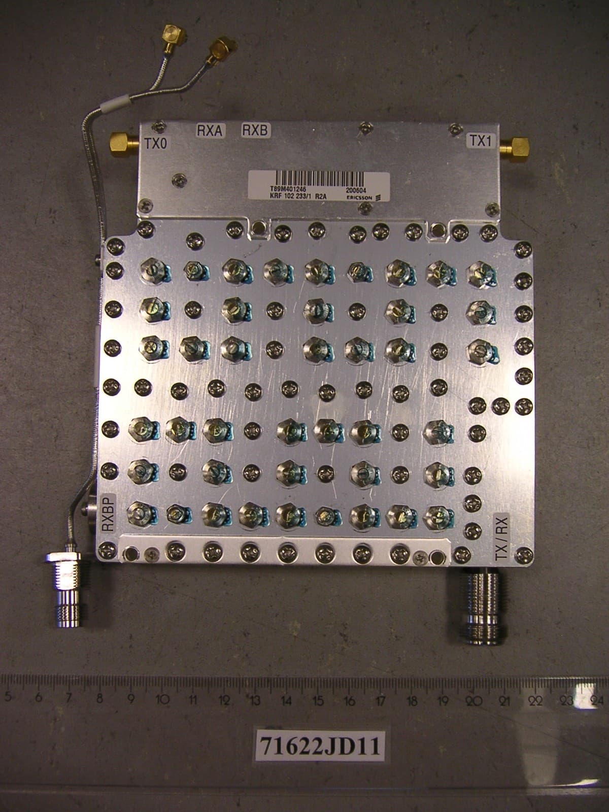
B5KCKRC16184-3
Sep 26, 2006PCS Broadband GSM Base station
Equipment Class
PCB - PCS Licensed Transmitter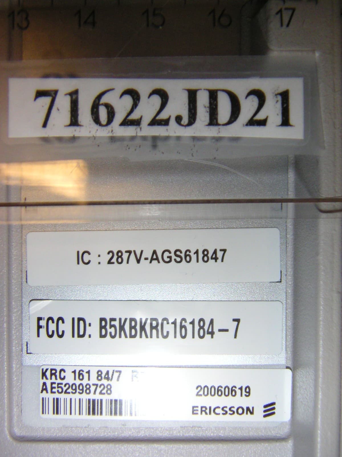
B5KCKRC16184-7
Sep 26, 2006PCS Broadband GSM Base station
Equipment Class
TNB - Licensed Non-Broadcast Station Transmitter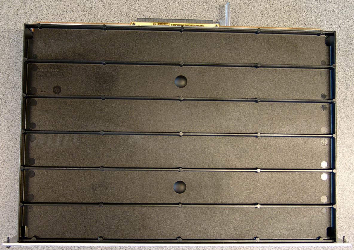
B5KDKRC1311005-2
Sep 06, 2006Broadband GSM Base station transceiver
Equipment Class
TNB - Licensed Non-Broadcast Station Transmitter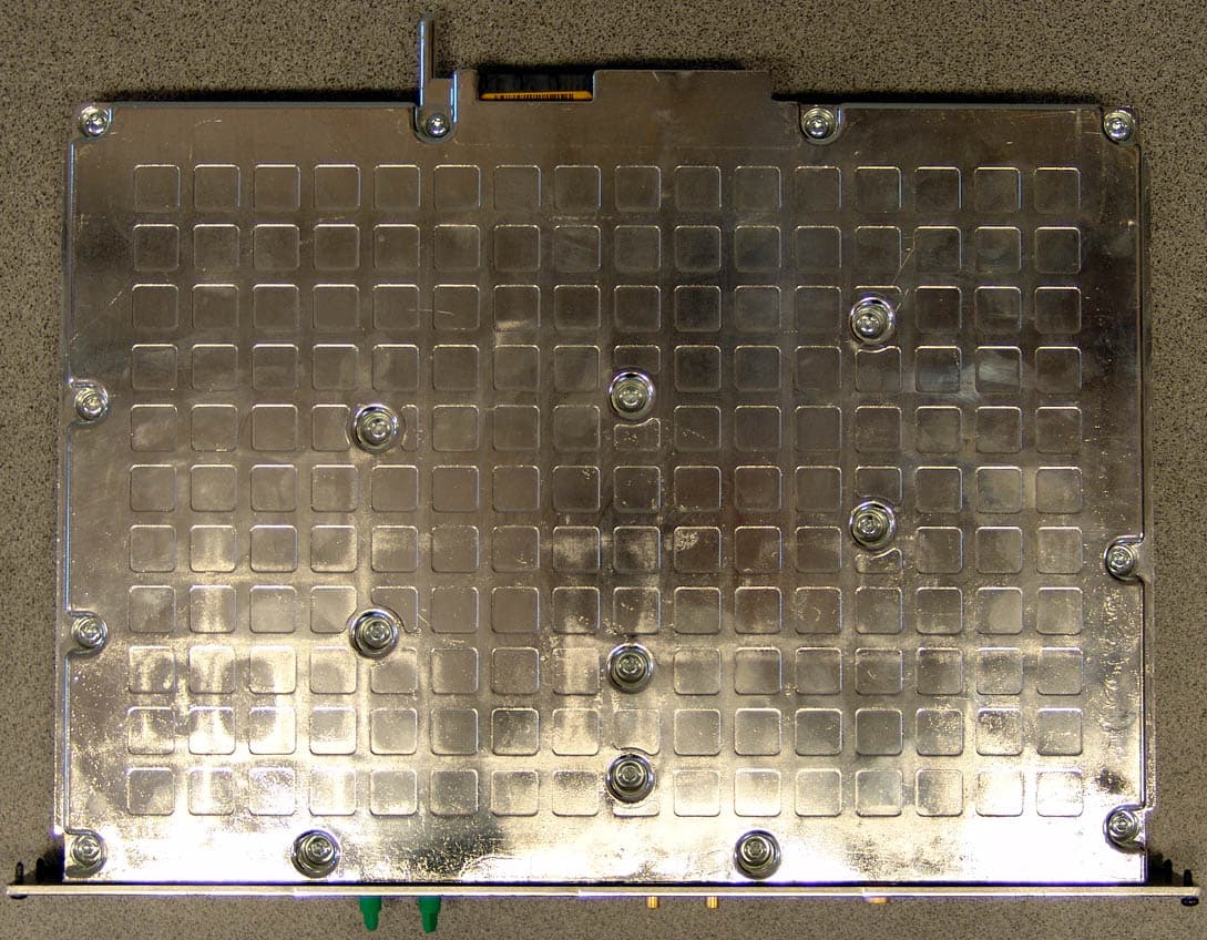
B5KAKRC1311013-2
Apr 04, 2005Broadband GSM Base station transceiver
Equipment Class
PCB - PCS Licensed Transmitter