BBD2-2ABRF Power Amplifier
TPL Communications Inc
Click to zoom
Application Details
- Equipment Class
- AMP - Amplifier
- Date of Grant
- Jan 30, 2006
- Application Purpose
- Original Equipment
- Date of Application
- Jan 30, 2006
- Equipment Note
- RF Power Amplifier
- Frequency Range
- 72.00000000 - 76.00000000
- Company
- TPL Communications Inc
- Country
- United States
Documents & Files
Document Text
Text extracted from the exhibit documents filed with the FCC. Open a document above to read the original.
Users Manual
I I ~ e~~~~ I I USER MANUAL I MID-BAND VHF I CONTINUOUS DUTY I POWER AMPLIFIERS I I I I I 3370 SAN FERNANDO ROAD., #206 I LOS ANGELES, CA 90065 TEL: (323)256-3000 FAX: (323)254-3210 I www.tplcom.com I I L-P A2- 2AX -RXRPS/RSPS- L5 I I - ~l TABLE OF CONTENTS I I .GENERAL SPECIFICATIONS 2 OPERATING PRECAUTIONS 4 I INSTALLATION 4 I REMOTEMONITORING 5,1 OPERATOR ADJUSTMENTS 6 .WARRANTY 8 D I ,I ,- c I .' , I I I I I I I I -GENERAL SPECIFICATIONS [ I FREQUENCY RANGE: 72-76 MHz MODEL POWER INPUT POWER OUTPUT DC CURRENT DRAIN I PA2-2AB-RSPS-P 0.5-1 W 10 W 1.5 Amps. PA2-2AC-RXR-PS-P 0.5-1 W 60 W 4 Amps. I OPERATING MODE: .I FM/CW OPERATING VOLTAGE: I 110 VAC " c, ,.:1 EIA DUTY CYCLE: 100% I Continuous I HARMONIC AND SPURIUS EMISSIONS ATTENUATION:1 Meets or exceeds FCC Certification requirements.:1 IN/OUT IMPEDANCE: 50 Ohms. 1 IN/OUT RF CONNECTORS: 1 Type "N" RECEIVER PATH INSERTION LOSS:1 1 dB maximum11 I ,I Page 2.1 I IGeneral Specifications (continued) II OPERATING TEMPERATURE: I -200 to +500 Celsius. I STORAGE TEMPERATURE: -400 to +850 Celsius. I OPERATING HUMIDITY:':1 0% -85% RH (non-condensing). STORAGE HUMIDITY: I 0% -95% RH (non-condensing). I I I I I I I I I ~ Page 3 I I -OPERATING PRECAUTIONS fJCAUTION: This amplifier produces RF voltages that can cause painful and dangerous l RF burns. Use caution! Connect and disconnect all RF connections with the DC power and drive power off. I DRIVE POWER: RF power transistors, although quite rugged in most respects, are easily damaged by overdrive. Be careful no to overdrive this amplifier, even for Ian instant. Higher than rated drive power may destroy the transistor and VOID ANY WARRANTY. ITERMINATIONS: The efficiency of this amplifier will degrade if it is operated into anything but a 50 Ohm load. Lowered effeciency may mean any, or all, of the follow ing: lower power output, increased current drain, higher opearating tem- 1 perature, and reduced life time. 1 INSTAllATION ~ This unit is designed for mounting in a standard 19" rack. When picking a location in the rack, cosideration must be given to the RF power output cable lengths, as well as cooling consider- I ations. Mount the unit where dust and other debris are not likely to clog the cooling fins. Avoid mount- ling the amplifier directly above hot pieces of equipment that could artificially raise the amplifi- ers temperature. IConnect the radio tranmsitter to the "RF INPUT" connector with a 50 Ohm c.~ble ~nd a type , "N" plug. Connect the antenna to the "RF OUTPUT" connector on the amplifier with 50 Ohm coaxial cable and a type "N" plug. I Plug the AC line cord into the system AC power receptacle.1 For safety, ensure that the rack and all equipment connected to the amplifier have properAC grounds. Do not rely on coaxial cable shielding. Assure the installation has proper lightning protection (e.g. in line coaxial protectors manufactured by PolyPhaser Corporation or equiva-::1 lent). I I I Page 4 I I -REMOTE MONITORING 11 The monitored functions are described in other sections. These same functions are available at the REMOTE MONITOR OB-9 connector on the rear panel. The outputs are as follows: I Monitor Signals I IChassis GNO 1 Ground and Signal Ground 'I Reflected 8 V max, 1Am max VRM 2 Power Buffer Analog alarm on = I Monitor 5.0 V Ph TAt" 0.5 mA us -0-- c lVe I PTT 3 Talk Input Low 5 V max max IOver0At.20 mA en c lVe OTMP 4 Temperat- CP IItL30 V max max AI0 ec or ow ure arm I 20 mA VCC 5 +5 Volts Reference Supply +5 VOC max I .20mA RFON 6 RF Input Open ActIVe 30 V max max I On Collector Low IForward 5 V @ 1A" m max VFM 7 Power Buffer Analog nominal Monitor output I Standing 20 mA". Wave Open Active SWR 8 Rt.CIItL30 V max max Ia 10 0 ec or ow ., Alarm ILow0At.20 mA pen c lVe LP A 9 Power CIItL30 V max max Alarm 0 ec or ow I Page 5 I I I I OPERATOR ADJUSTMENTS The operator adjustments are accessible through a slot in the cover of the RF enclosure. IThese are 10-turn potentiometers VR1 through VR5 and switch SW1. Their functions are as follows: I Ref. Des. Function I Adjustment I VR1 Determines the threshold for a valid input RF power level. VR2 Low RF power output threshold set to determine the alarm level for the LPA I signal at the Remote Monitor connector. VR3 Sets the Forward Power Monitor (VFM) voltage at the Remote Monitor connector. I VR4 SWR threshold set to determine the alarm level for the SWR signal at the Remote Monitor connector. I VR5 Sets the RF output power level. I SW1 Determines the method of RF output power control. The TEST position provides regulated DC control. The OPER position provides RF feedback leveling control. I A basic understanding of RF principals is necessary before making any adjustments to the Iunit. This includes the knowledge of the relationship of forward and reflected power relative to SWR, etc. Adjustment also requires the familiarity and use of test equipment. If in doubt, consult your distributor, dealer or the manufacturer about changes. I I I I 'I " 1Page 6 I I I OPERATOR ADJUSTMENTS ~ Switch SW2, located inside the RF enclosure, is set according to the particular configuration of each amplifier. This switch is factory set at the time of manufacture and should not be I changed. Never turn on more than one switch at any time! I SW2 -1 -2 -3 -4 14V / REM on off off off I 28V / REM off on off off 14V/PSC off off on off r I 28V / PSG off off off on I IThe necessary adjustment procedure to change the RF power level must be done in the sequence shown as follows: ,I Provide a proper low-VSWR RF termination for the amplifier. 1. Place SW1 into the RUN position. I 2. Apply the minimum RF drive level and adjust VR5 for nominal output power. I 3. With nominal RF output, measure the voltage on pin 7 of the monitor connector (VFM) and adjust VR3 to obtain 5 volts I 4. Reduce input drive by 3 dB and adjust VR1 so the RFON signal at pin 6 of the monitor connector goes low I 5. Restore minimum drive and set the output power down 3 dB from nominal with VR5. Adjus…
Text truncated - open the document above for the full version.
ID Label/Location Info
PROPOSED FCC ID LABEL AND LOCATION TPL COMMUNICATION This device complies with Part 22/90 of the FCC Rules. FCC ID: BBD2-2AB FCC ID LABEL LOCATION
Test Report
FCC CFR47 PART 22, SUBPART C AND FCC CFR47 PART 90, SUBPART I CERTIFICATION TEST REPORT FOR RF POWER AMPLIFIER MODEL NUMBER: PA2-2AB-RSPS-P FCC ID: BBD2-2AB REPORT NUMBER: 05U3886-1 ISSUE DATE: DECEMBER 29, 2005 Prepared for TPL COMMUNICATION 3370 SAN FERNANDO ROAD, SUITE 206 LOS ANGELES, CA 90065, USA Prepared by COMPLIANCE ENGINEERING SERVICES, INC. d.b.a. COMPLIANCE CERTIFICATION SERVICES 561F MONTEREY ROAD, MORGAN HILL, CA 95037, USA TEL: (408) 463-0885 FAX: (408) 463-0888 REPORT NO: 05U3886-1 DATE: DECEMBER 29, 2005 EUT: RF POWER AMPLIFIER FCC ID: BBD2-2AB Page 2 of 31 COMPLIANCE CERTIFICATION SERVICES DOCUMENT NO: CCSUP4031A 561F MONTEREY ROAD, MORGAN HILL, CA 95037 USA TEL: (408) 463-0885 FAX: (408) 463-0888 This report shall not be reproduced except in full, without the written approval of CCS. Revision History Rev. Issue Date Revisions Revised By A 12/29/05 Initial Issue Thu REPORT NO: 05U3886-1 DATE: DECEMBER 29, 2005 EUT: RF POWER AMPLIFIER FCC ID: BBD2-2AB Page 3 of 31 COMPLIANCE CERTIFICATION SERVICES DOCUMENT NO: CCSUP4031A 561F MONTEREY ROAD, MORGAN HILL, CA 95037 USA TEL: (408) 463-0885 FAX: (408) 463-0888 This report shall not be reproduced except in full, without the written approval of CCS. TABLE OF CONTENTS 1. ATTESTATION OF TEST RESULTS............................................................................................. 4 2. TEST METHODOLOGY .................................................................................................................. 5 3. FACILITIES AND ACCREDITATION .......................................................................................... 5 4. CALIBRATION AND UNCERTAINTY.......................................................................................... 5 4.1. MEASURING INSTRUMENT CALIBRATION ............................................................................. 5 4.2. MEASUREMENT UNCERTAINTY ............................................................................................... 5 5. EQUIPMENT UNDER TEST............................................................................................................6 5.1. DESCRIPTION OF EUT ..............................................................................................................6 5.2. MAXIMUM OUTPUT POWER .................................................................................................... 6 5.3. WORST-CASE CONFIGURATION AND MODE......................................................................... 6 5.4. DESCRIPTION OF TEST SETUP ................................................................................................ 7 6. TEST AND MEASUREMENT EQUIPMENT ................................................................................ 9 7. LIMITS AND RESULTS ................................................................................................................. 10 7.1. OCCUPIED BANDWIDTH ........................................................................................................ 10 7.2. FM EMISSION LIMITATION ..................................................................................................... 15 7.3. MODULATION CHARACTERISTICS........................................................................................ 20 7.4. RF POWER OUTPUT.................................................................................................................20 7.5. VOLTAGE STABILITY................................................................................................................ 23 7.6. FREQUENCY STABILITY .......................................................................................................... 24 7.7. SPURIOUS EMISSION AT ANTENNA TERMINAL................................................................... 24 7.8. FIELD STRENGTH OF SPURIOUS RADIATION..................................................................... 27 7.8.1. SPURIOUS RADIATION .................................................................................................. 28 8. SETUP PHOTOS .............................................................................................................................. 29 REPORT NO: 05U3886-1 DATE: DECEMBER 29, 2005 EUT: RF POWER AMPLIFIER FCC ID: BBD2-2AB Page 4 of 31 COMPLIANCE CERTIFICATION SERVICES DOCUMENT NO: CCSUP4031A 561F MONTEREY ROAD, MORGAN HILL, CA 95037 USA TEL: (408) 463-0885 FAX: (408) 463-0888 This report shall not be reproduced except in full, without the written approval of CCS. 1. ATTESTATION OF TEST RESULTS COMPANY NAME: TPL COMMUNICATION 3370 SAN FERNANDO ROAD, SUITE 206 LOS ANGELES, CA 90065 USA EUT DESCRIPTION: RF POWER AMPLIFIER MODEL: PA2-2AB-RSPS-P SERIAL NUMBER: 01650 DATE TESTED: DECEMBER 13-14, 2005 APPLICABLE STANDARDS STANDARD TEST RESULTS FCC PART 22 SUBPART C NO NON-COMPLIANCE NOTED FCC PART 90 SUBPART I NO NON-COMPLIANCE NOTED Compliance Certification Services, Inc. tested the above equipment in accordance with the requirements set forth in the above standards. The test results show that the equipment tested is capable of demonstrating compliance with the requirements as documented in this report. Note: The results documented in this report apply only to the tested sample, under the conditions and modes of operation as described herein. This document may not be altered or revised in any way unless done so by Compliance Certification Services and all revisions are duly noted in the revisions section. Any alteration of this document not carried out by Compliance Certification Services will constitute fraud and shall nullify the document. No part of this report may be used to claim product certification, approval, or endorsement by NVLAP, NIST, or any government agency. Approved & Released For CCS By: Tested By: THU CHAN CHIN PANG EMC SUPERVISOR EMC ENGINEER COMPLIANCE CERTIFICATION SERVICES COMPLIANCE CERTIFICATION SERVICES REPORT NO: 05U3886-1 DATE: DECEMBER 29, 2005 EUT: RF POWER AMPLIFIER FCC ID: BBD2-2…
Text truncated - open the document above for the full version.
Test Setup Photos
REPORT NO: 05U3886-1 DATE: DECEMBER 29, 2005 EUT: RF POWER AMPLIFIER FCC ID: BBD2-2AB Page 29 of 31 COMPLIANCE CERTIFICATION SERVICES DOCUMENT NO: CCSUP4031A 561F MONTEREY ROAD, MORGAN HILL, CA 95037 USA TEL: (408) 463-0885 FAX: (408) 463-0888 This report shall not be reproduced except in full, without the written approval of CCS. 8. SETUP PHOTOS ANTENNA PORT CONDUCTED RF MEASUREMENT SETUP ANTENNA PORT CONDUCTED PHOTO REPORT NO: 05U3886-1 DATE: DECEMBER 29, 2005 EUT: RF POWER AMPLIFIER FCC ID: BBD2-2AB Page 30 of 31 COMPLIANCE CERTIFICATION SERVICES DOCUMENT NO: CCSUP4031A 561F MONTEREY ROAD, MORGAN HILL, CA 95037 USA TEL: (408) 463-0885 FAX: (408) 463-0888 This report shall not be reproduced except in full, without the written approval of CCS. RADIATED RF MEASUREMENT SETUP RADIATED FRONT PHOTO REPORT NO: 05U3886-1 DATE: DECEMBER 29, 2005 EUT: RF POWER AMPLIFIER FCC ID: BBD2-2AB Page 31 of 31 COMPLIANCE CERTIFICATION SERVICES DOCUMENT NO: CCSUP4031A 561F MONTEREY ROAD, MORGAN HILL, CA 95037 USA TEL: (408) 463-0885 FAX: (408) 463-0888 This report shall not be reproduced except in full, without the written approval of CCS. END OF REPORT RADIATED BACK PHOTO
Contact Information
Applicant
Lenny Uchenik(VP, Engineering)
Test Firm
Compliance Certification Services IncSteve Cheng
Technical Specifications
| # | Rule Parts | Frequency Range | Power Output | Emission | Tolerance |
|---|---|---|---|---|---|
| 1 | 22,90 | 72 MHz - 76 MHz | 10 W | F3E | Amp |
Other Applications from TPL Communications Inc
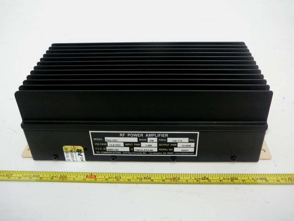
BBD3-60
Oct 09, 2012RF Power Amplifier
Equipment Class
AMP - Amplifier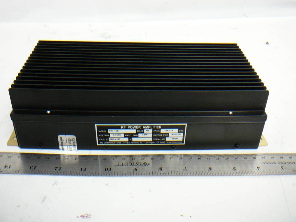
BBD3-125
Oct 01, 2012RF Power Amplifier
Equipment Class
AMP - Amplifier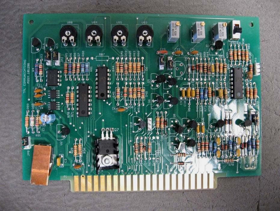
BBDPA9096-350
Oct 27, 2011RF Power Amplifier
Equipment Class
AMP - Amplifier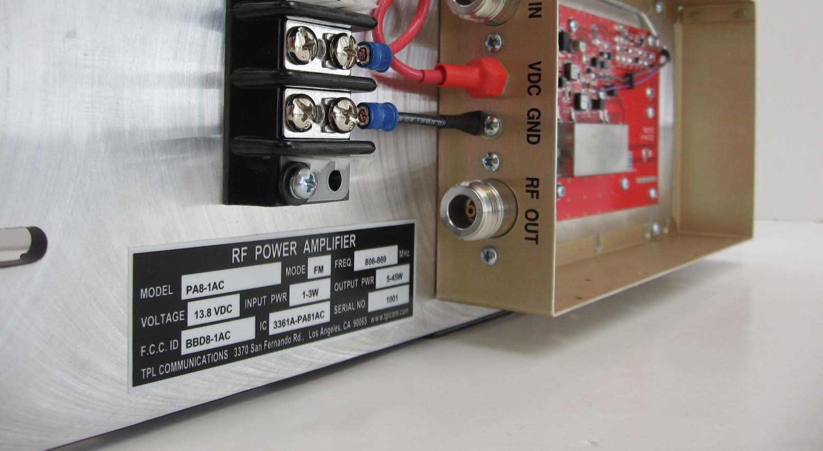
BBD8-1AC
Mar 31, 2010RF Power Amplifier
Equipment Class
AMP - Amplifier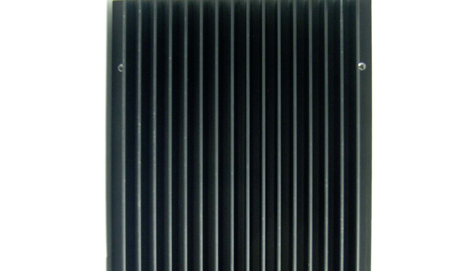
BBD1-1AEL
Aug 13, 2007RF Power Amplifier
Equipment Class
AMP - Amplifier