BBD6-1AERF Amplifier
TPL Communications Inc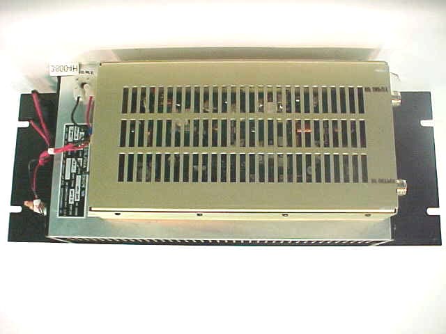
Click to zoom
Application Details
- Equipment Class
- AMP - Amplifier
- Date of Grant
- Aug 13, 2003
- Application Purpose
- Original Equipment
- Date of Application
- Aug 13, 2003
- Equipment Note
- RF Amplifier
- Frequency Range
- 400.00000000 - 512.00000000
- Company
- TPL Communications Inc
- Country
- United States
Documents & Files
Document Text
Text extracted from the exhibit documents filed with the FCC. Open a document above to read the original.
Cover Letter(s)
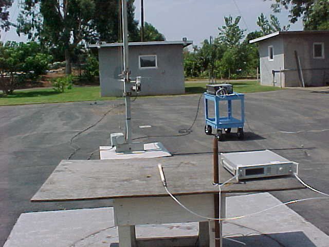
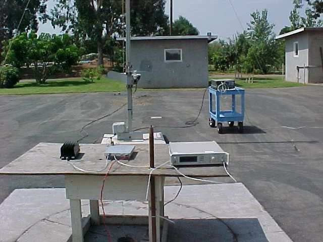
Responese from DNB Engineering. -----Original Message----- From: Les Payne [mailto:[email protected]] Sent: Tuesday, July 29, 2003 1:44 PM To: 'Anne Liang' Subject: RE: TPL COMMUNICATIONS, FCC ID: BBD6-1AE, Assessment NO.: AN03T3040 (#2) Greetings Anne, Please review and send grant as quickly as possible. Customer is getting very upset.. Les -----Original Message----- From: Compliance Certification Services [<mailto:[email protected]>mailto:[email protected]] Sent: Tuesday, July 22, 2003 2:35 PM Subject: TPL COMMUNICATIONS, FCC ID: BBD6-1AE, Assessment NO.: AN03T3040 (#2) 1. FCC rule para 2.925 requires the words "FCC ID" to be placed before the FCC identifier. Please submit revised label drawings or photographs that show compliance with this requirement. See attached label 2. The product interior photographs do not seem to have sufficient resolution. Please re-submit or re-scan at a higher resolution. New photos submitted jpg format 3. Will the amplifier be sold for use with 12.5 kHz channel bandwidth equipment? If so, the limit for emissions removed by more than 12.5 kHz must be suppressed by at least 50+10log(Pwatts). i.e., they must be less than -20dBm . The display line shown on the spuruios emissions graphs is -13 dBm. Please comment. New data sheet provided, please replace pages 53, 54 and 55 with new 53 and 54. 4. For spurious emission field strength emissions required by rule para. 2.1053, emissions are referenced to the radiated output power of the transmitter, assuming all emissions are radiated from a dipole. FCC interprets this to mean that the "substitution" method must be used to determine compliance. This method called out by EIA/TIA 603 specification (among others) requires that once radiated emissions from the EUT have been measured, the EUT is removed and a signal generator and substitution antenna is put in its place. Emissions are again maximized, the signal generator is set to match the radiated reading, and the resultant ERP is compared against the limit. Please submit data for radiated emissions performed in this fashion.Ê Submitted same as Item 3 5. Please submit a photograph showing the radiated emissions test set-upTypical Set up phots submitted The items indicated above must be submitted before processing can continue on the above referenced application. Failure to provide the requested information within 60 days of the original e-mail date may result in application dismissal and forfeiture of the filing fee. Also, please note that partial responses increase processing time and should not be submitted. Any questions about the content of this correspondence should be directed to the e-mail address listed below the name of the sender.
Cover Letter(s)
Delivered-To: trephonc-tncokenias:[email protected] From: "Les Payne" <[email protected]> To: "Tom Cokenias" <[email protected]> Cc: "Chris Landsberger" <[email protected]> Subject: TPL Amplifiers Date: Wed, 10 Sep 2003 14:01:14 -0700 X-Priority: 3 (Normal) Importance: Normal Greetings Tom, Corrections to TPL Amplifiers BBD8-1ED incorrect frequency range listed is 800-860 should be 800-960 BBD3,BBD6 and BBD8 amplifiers should include Part 22 as well as Part 90, Thanks Les
External Photos
FCC ID: BBD6-1AE 35 2.1033 (C) (12) Equipment Photographs - External Photo 5 Detail View – External – Front FCC ID: BBD6-1AE 36 2.1033 (C) (12) Equipment Photographs - External Photo 6 Detail View – External – Left Side FCC ID: BBD6-1AE 37 2.1033 (C) (12) Equipment Photographs - External Photo 7 Detail View – External - Rear FCC ID: BBD6-1AE 38 2.1033 (C) (12) Equipment Photographs - External Photo 8 Detail View – External – Right Side FCC ID: BBD6-1AE 39 2.1033 (C) (12) Equipment Photographs - External Photo 9 Detail View – External - Top FCC ID: BBD6-1AE 40 2.1033 (C) (12) Equipment Photographs - External Photo 10 Detail View – External - Bottom
Test Report
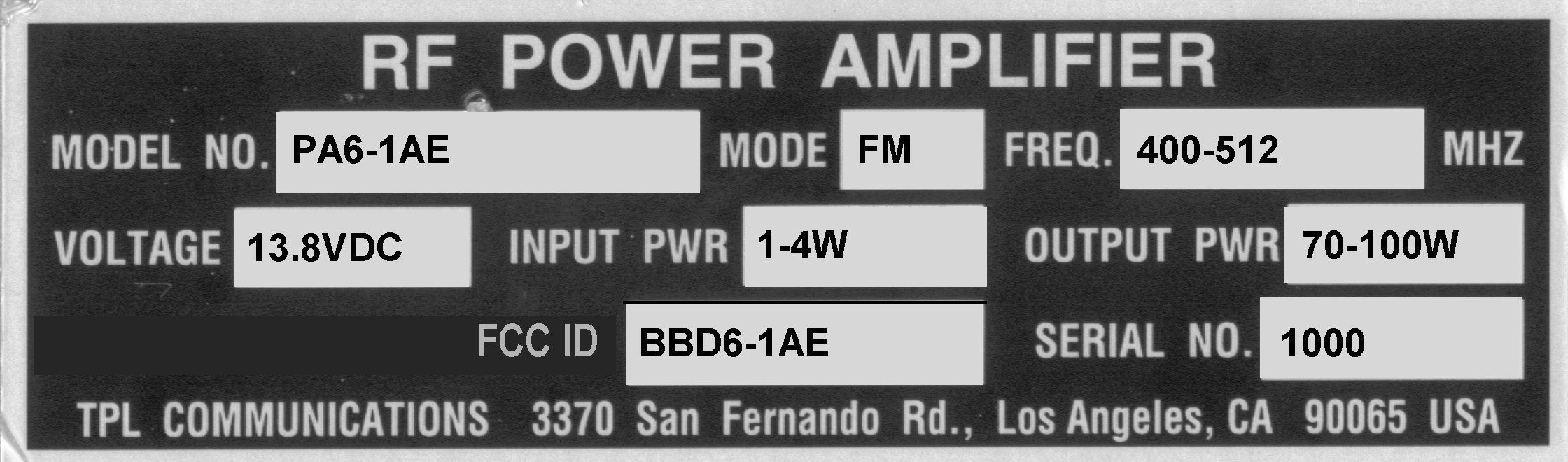
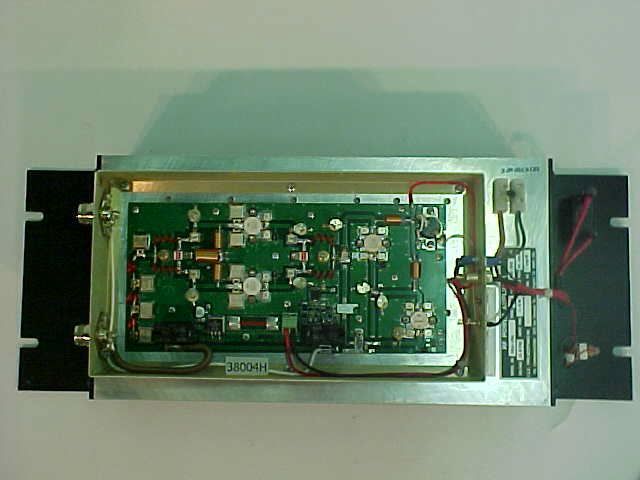
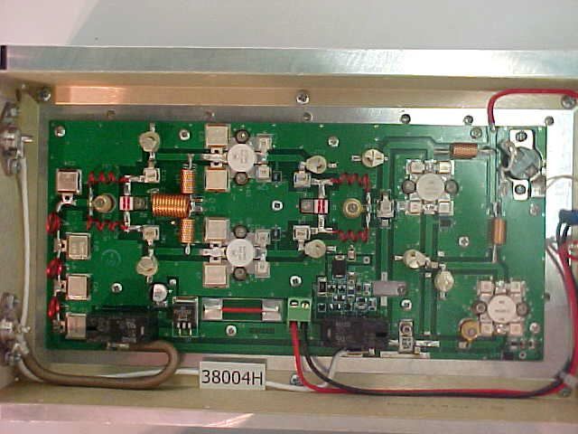
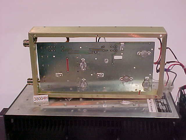
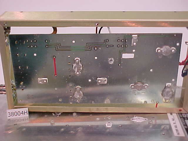
FCC ID: BBD6-1AE 1 Application for Certification For an RF Power Amplifier TPL Communications 3370 San Fernando Road, Suite 206 Los Angeles, CA 90065 RF Power Amplifier: Part # PA6-1AE FCC ID: BBD6-1AE REPORT # RV38004H This report was prepared in accordance with the requirements of the FCC Rules and Regulations Part 2, Subpart J, 2.1031 through 2.1057, and Part 90 and other applicable sections of the rules as indicated herein. Prepared By: C. L. Payne III DNB Engineering, Inc. 5969 Robinson Avenue Riverside, Ca 92503-8620 8 Jan 2003 FCC ID: BBD6-1AE 2 TABLE OF CONTENTS Section Title Sheet # 1.0 ADMINISTRATIVE DATA 3 1.1 Certifications and Qualifications 3 1.2 Measurements and Repeatability Information 3 Note: Paragraph numbers in this report follow the application section numbers found in the FEDERAL COMMUNICATIONS COMMISSION Rules and Regulations, Part 2, Subpart J for Certification of electronic equipment. 2.1033 (C) (1) Application for Certification 4 2.1033 (C) (2) FCC Identifier 5 2.1033 (C) (3) Installation and Operating Instructions (Service manual) 6-21 2.1033 (C) (4) Type of Emissions 22 2.1033 (C) (5) Frequency Range 23 2.1033 (C) (6) Operating Power 24 2.1033 (C) (7) Maximum Power Allowed in Applicable part(s) of the Rules 25 2.1033 (C) (8) Final RF Amplifier Input Power Characteristics 26 2.1033 (C) (9) Tune Up Procedure 27 2.1033 (C) (10) Schematic Diagram and Circuit Description 28-39 2.1033 (C) (11) Equipment Identification Plate 30 2.1033 (C) (12) Equipment Photographs (Internal) 31-34 2.1033 (C) (12) Equipment Photographs (External) 35-40 2.1033 (C) (13) Digital Modulation Techniques 41 2.1033 (C) (14) Test Data 42 Test Set-Up 43-44 2.1046 Measurement of RF Power Output 45-46 2.1049 Measurement of Occupied Bandwidth 47-48 2.1051 Spurious Emissions at Antenna Terminals 49-52 2.1053 Measurement of Field Strength of Spurious Radiation 53-55 2.1055 Measurement of Frequency Stability 56 2.1057 Frequency Spectrum to be Investigated 57 RF Exposure 58 Test Equipment Log 59 FCC ID: BBD6-1AE 3 1.0 ADMINISTRATIVE DATA 1.1 Certifications and Qualifications I certify that DNB Engineering, Inc conducted the tests performed in order to obtain the technical data presented in this application. Also, based on the results of the enclosed data, I have concluded that the equipment tested meets or exceeds the requirements of the Rules and Regulations governing this application. 1.2 Measurement Repeatability Information The test data presented in this report has been acquired using the guidelines set forth in FCC Part 2.1031 through 2.1057, and Part 90. The test results presented in this document are valid only for the equipment identified herein under the test conditions described. Repeatability of these test results will only be achieved with identical measurement conditions. These conditions include: The same test distance, EUT Height, Measurement Site Characteristics, and the same EUT System Components. The system must have the same Interconnecting Cables arranged in identical placement to that in the test set-up, with the system and/or EUT functioning in the identical mode of operation (i.e. software and so on) as on the date of the test. Any deviation from the test conditions and the environment on the date of the test may result in measurement repeatability difficulties. All changes made to the EUT during the course of testing as identified in this test report must be incorporated into the EUT or identical models to ensure compliance with the FCC regulations. C. L. Payne III (Para. 1.1) Manager, Commercial Products. DNB Engineering, Inc. Tel. (909) 637-2630 Fax (909) 637-2704 E-mail [email protected] FCC ID: BBD6-1AE 4 2.1033 (C) (1) Application for Certification Name of Applicant: TPL Communications 3370 San Fernando Road, Suite 206 Los Angeles, Ca 90065 FRN: 0008271447 Applicant is: X Manufacturer Vendor Licensee Prospective Licensee Other Name of Manufacturer TPL Communications Description: RF Power Amplifier Part Number: PA6-1AE Anticipated Production Quantity: Multiple Units Applicable FCC Parts: 90 FCC ID No: BBD6-1AE FCC Emissions Designator: F3E Frequency Range: 450 – 512 MHz Rated Output Power: 70 - 100W FCC ID: BBD6-1AE 5 2.1033 (C) (2) FCC Identifier FCC ID: BBD6-1AE FCC ID: BBD6-1AE 21 2.1033 (C) 3) Installation and Operating Instructions FCC ID: BBD6-1AE 22 2.1033 (C) (4) Type of Emission N/A (FM Modulation) Emission Designator: F3E FCC ID: BBD6-1AE 23 2.1033 (C) (5) Frequency Range 400-512MHz (Factory set for 460MHz) FCC ID: BBD6-1AE 24 2.1033 (C) (6) Operating Power 70 - 100 Watts FCC ID: BBD6-1AE 25 2.1033 (C) (7) Maximum Power Allowed in Applicable Part(s) of the Rules RULES PART MAXIMUM POWER (WATTS) Part 90.205(q) 120 FCC ID: BBD6-1AE 30 2.1033 (C) (11) Equipment Identification Plate NOTES: Label will be constructed of 0.02 inch aluminum as shown on the equipment with permanent adhesive. All information on the label will be etched or stamped. Both methods will exceed the expected lifetime of the equipment. The label will be large enough to allow all information to be legible. FCC ID: BBD6-1AE 31 2.1033 (C) (12) Equipment Photographs - Internal Photo 1 Detail View – Internal – Component Side of PCB FCC ID: BBD6-1AE 32 2.1033 (C) (12) Equipment Photographs - Internal Photo 2 Detail View – Internal – Component Side of PCB – Close Up FCC ID: BBD6-1AE 33 2.1033 (C) (12) Equipment Photographs - Internal Photo 3 Detail View – Internal – Circuit Side of PCB FCC ID: BBD6-1AE 34 2.1033 (C) (12) Equipment Photographs - Internal Photo 4 Detail View – Internal – Circuit Side of PCB – Close Up FCC ID: BBD6-1AE 35 2.1033 (C) (12) Equipment Photographs - External Photo 5 Detail View – External – Front FCC ID: BBD6-1AE 36 2.1033 (C) (12) Equipment Photographs - External Photo 6 Detail View – External – Left Side FCC ID: BBD6-1AE 37 2.1033 (C) (12) Equipment Photographs - External Photo 7 Detail View – External - Rear FCC ID: BBD6-1AE 38 2.1033 (C) (12) Equipment Photographs - Externa…
Text truncated - open the document above for the full version.
Test Report
FCC ID: BBD6-1AE 53 2.1053 Field Strength of Spurious Radiation Definition: Emissions from the equipment when connected into a non-radiating load on a frequency or frequencies which are outside an occupied band sufficient to ensure transmission of information of required quality for the class of communication desired. The reduction in the level of these spurious emissions will not affect the quality of the information being transmitted. Test Method: Per TIA /EIA 603. Connect the equipment and follow the procedure described in paragraph 2.2.1.1 and paragraph 5.0. Measure the amplitude of each spurious radiated signal through the 10 th harmonic. The spurious signals are then measured on the 3 meter range. First the EUT is measured using a tuned reference dipole below 1GHz and a double ridge guide Horn antenna above 1GHz. If the DRG antenna is used the appropriate gain factor for the antenna is subtracted from the final measurement. Then a dipole to dipole (or drg to drg) measurement is conducted to determine the actual power at each harmonic being generated by the EUT. If no noticeable emission can be observed the ground floor is recorded in the data sheets. Test Results: All readings were at the spectrum analyzer ground floor above the fundamental. All radiated spurious emissions are below the FCC Specifications. FCC ID: BBD6-1AE 54 5969 Robinson Avenue Riverside, CA 92503 (909) 637-2630 FAX (909) 637-2704 Radiated Spurious DNB Job Number: 38004 Date: 29 August 2002 Customer: TPL Communications Model Number: PA6-1AE Serial Number: 1000 RF Amplifier Description: Conformance Standards [X] FCC Part 15 [X] FCC Part 90 Fundamental Freq In MHz Rated Output Power In Watts Channel Spacing In kHz Modulation 460 70-100 12.5 , 25 FM Limit (dBm) Freq (MHz) Antenna Horn Gain Meter Power Corrected 12.5kHz BW 25.0kHz BW 920 Dipole - Hz N/A -16.0 -27.8 -27.8 -13 -20 1380 Horn - Hz 7.5 -34.8 -48.6 -56.1 -13 -20 1840 Horn – Hz 7.8 -15.9 -29.7 -37.5 -13 -20 2300 Horn – Hz 8.0 -35.5 gf -20.0* -28.0 -13 -20 2760 Horn – Hz 8.7 -37.1 gf -20.0 * -28.7 -13 -20 3220 Horn – Vt 8.9 -38.0 gf -20.0 * -28.9 -13 -20 3680 Horn - Hz 9.1 -37.6 gf -20.0 * -29.1 -13 -20 4140 Horn - Hz 9.4 -38.9 gf -20.0 * -29.4 -13 -20 4600 Horn - Hz 10.0 -37.9 gf -20.0 * -30.0 -13 -20 * Signal generator had a bottom level of –20dBm which represents the ground floor when using the substitution method.
Contact Information
Applicant
Lenny Uchenik(VP, Engineering)
Test Firm
DNB Engineering, Inc.Mike Neis
Technical Specifications
| # | Rule Parts | Frequency Range | Power Output | Emission | Tolerance |
|---|---|---|---|---|---|
| 2 | 22 | 400 MHz - 512 MHz | 100 W | F3E | Amp |
Other Applications from TPL Communications Inc
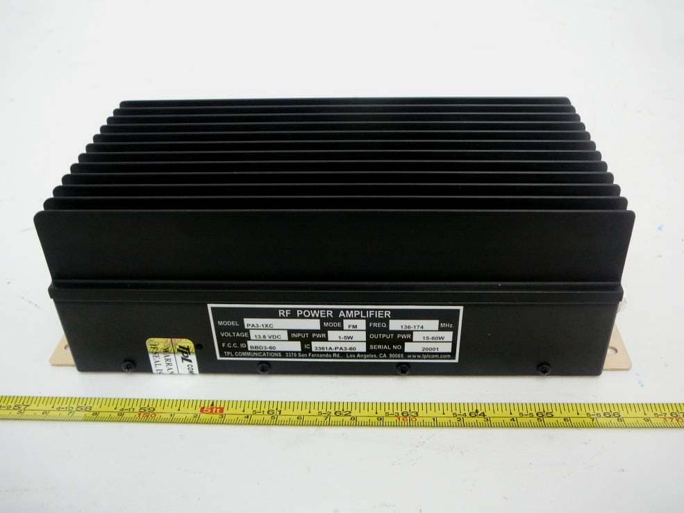
BBD3-60
Oct 09, 2012RF Power Amplifier
Equipment Class
AMP - Amplifier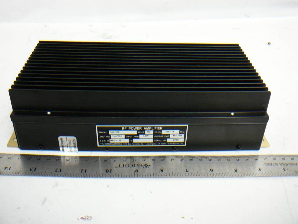
BBD3-125
Oct 01, 2012RF Power Amplifier
Equipment Class
AMP - Amplifier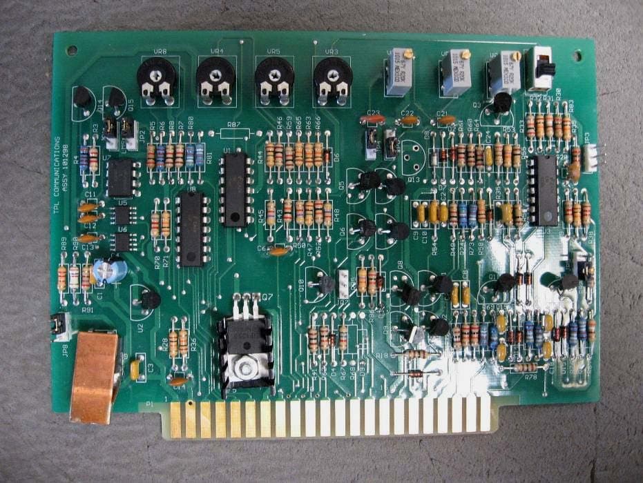
BBDPA9096-350
Oct 27, 2011RF Power Amplifier
Equipment Class
AMP - Amplifier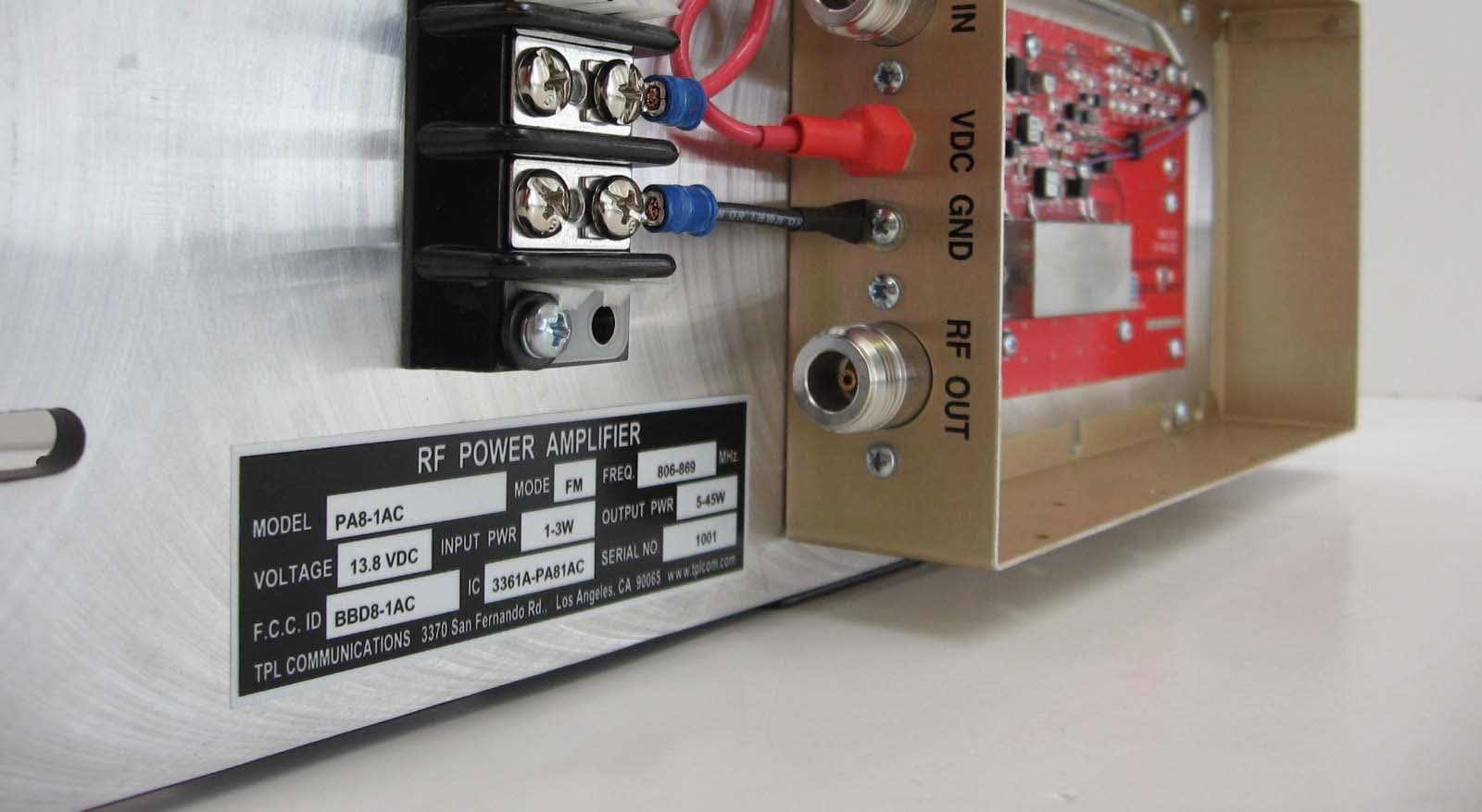
BBD8-1AC
Mar 31, 2010RF Power Amplifier
Equipment Class
AMP - Amplifier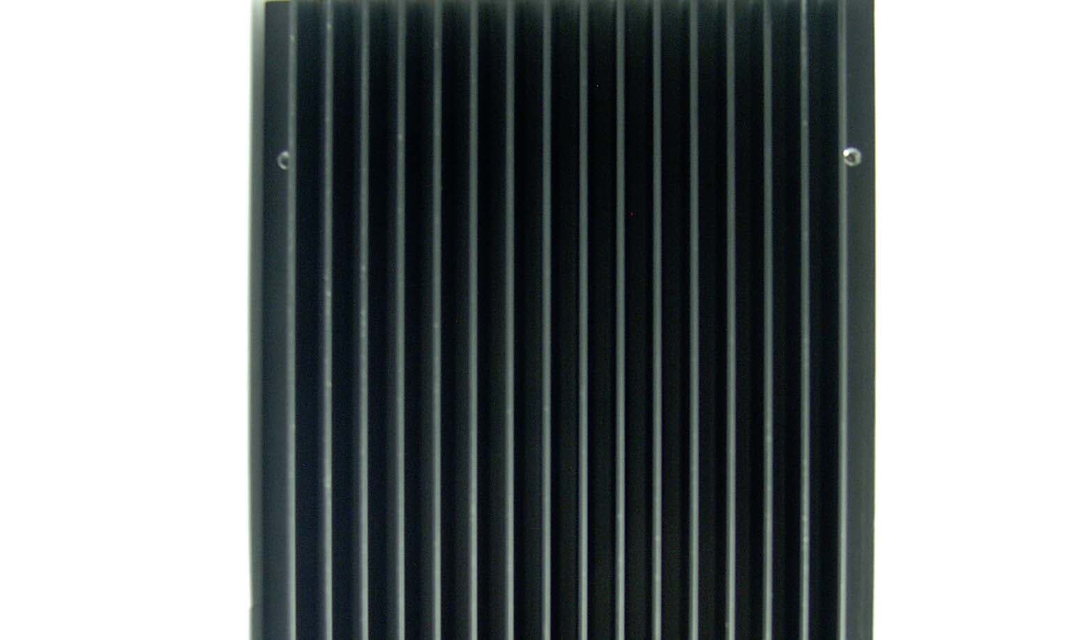
BBD1-1AEL
Aug 13, 2007RF Power Amplifier
Equipment Class
AMP - Amplifier