BCR-BCEL-FAST900RF Distribution System
Andrew Wireless Innovations Group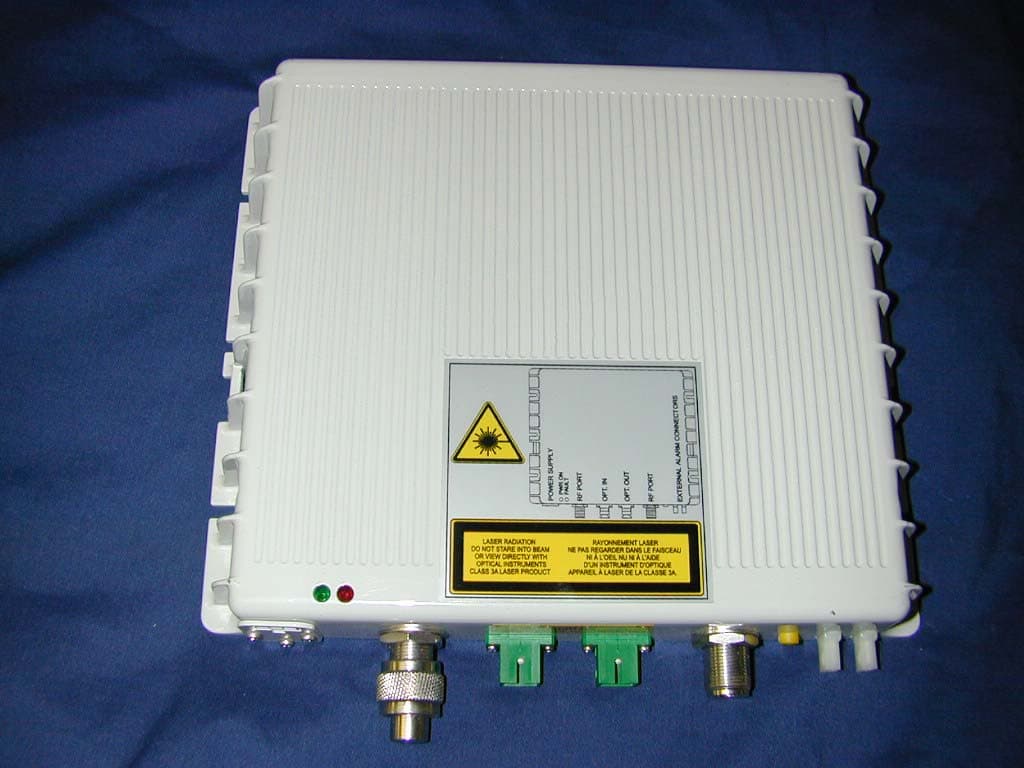
Click to zoom
Application Details
- Equipment Class
- PCB - PCS Licensed Transmitter
- Date of Grant
- Jul 17, 2003
- Application Purpose
- Original Equipment
- Date of Application
- Jul 17, 2003
- Equipment Note
- RF Distribution System
- Frequency Range
- 935.00000000 - 940.00000000
- Country
- United States
Documents & Files
Document Text
Text extracted from the exhibit documents filed with the FCC. Open a document above to read the original.
Users Manual
U U S S E E R R I I N N S S T T A A L L L L A A T T I I O O N N M M A A N N U U A A L L MN021-01 Page 1 of 28 INDEX 1. Installation & safety requirements.............................................................................................................................3 1.1. Environmental conditions:...........................................................................................................................3 1.2. Installation site features..............................................................................................................................3 1.3. Connection to the power.............................................................................................................................3 1.4. Safety and precautions during the installation.............................................................................................3 1.5. Safety and precautions for lasers................................................................................................................3 1.6. Connector care and cleaning......................................................................................................................4 2. Warning labels..........................................................................................................................................................4 3. Health and safety warnings.......................................................................................................................................5 4. System description....................................................................................................................................................6 4.1. Features......................................................................................................................................................6 4.2. Services......................................................................................................................................................7 4.3. Functional description.................................................................................................................................7 5. Functional description...............................................................................................................................................9 5.1. Block diagram.............................................................................................................................................9 5.2. Down link operations...................................................................................................................................9 5.3. Up link operations.......................................................................................................................................9 5.4. Remote supply..........................................................................................................................................10 5.5. Automatic Gain Control.............................................................................................................................10 6. Alarms and settings................................................................................................................................................10 6.1. Alarm contacts..........................................................................................................................................11 6.2. UL level setting.........................................................................................................................................11 6.3. Software auto-configuration......................................................................................................................11 7. Installation and Cabling...........................................................................................................................................12 7.1. Power supply............................................................................................................................................12 7.2. RF Ports....................................................................................................................................................13 7.3. Optical fibres connection...........................................................................................................................13 8. Troubleshooting......................................................................................................................................................14 9. Part description.......................................................................................................................................................15 10. Functional description...........................................................................................................................................16 10.1. Block diagram...........................................................................................................................................16 10.2. Up link operations.....................................................................................................................................16 10.3. Down link operations.................................................................................................................................16 10.4. Remote supply..........................................................................................................................................16 10.5. Automatic Gain Control.............................................................................................................................16 11. Alarms and settings..............................................................................................................................................17 11.1. Remote unit LEDs...................................................…
Text truncated - open the document above for the full version.
Cover Letter(s)
REQUEST FOR CONFIDENTIALITY Allen Telecom/Mikom US would like to request confidentiality with regard to the following documents in the filing for equipment approval identified by FCC ID. No. BCR-BCEL-FAST900 (1) Schematic diagrams contained in electronic file identified as schematics.pdf. It is the opinion of Allen Telecom/Mikom US disclosure of this information would result in significant loss of revenue. This information should be kept confidential for 30 years. Authorized signature Printed name Company name Company Address Only information that is not accessible to the general public may be held confidential. Generally internal and external photos cannot be held confidential. The exception would be if the PC board is polled.
ID Label/Location Info
FCC ID: __ BCR-BCEL-FAST900________ MADE IN E.E.C BY ALLEN TELECOM CANADA: ___________________________________________ SERIAL NO: ____________ MODEL NO: __________________ BriteCell Fast Remote TM TM TM
Parts List/Tune Up Info
Tune-up Procedure Step 1: Connect the BriteCell donor unit to the BriteCell remote unit using single mode fiber Step 2: Connect power to both units. Step 3: Input a TX test signal into the donor unit port (N-connector) Step 4: Measure the output power at one of the remote unit ports. This signal will be +7dB gain from the donor. Increase the gain until the spurs are above -13dBm Step 5: Input an RX test signal into the remote unit port. Step 6: Measure the output power at the donor unit port (N-connector). This signal will be +17dB gain from the remote unit. It is a good rule when working with the fibre optic components, to always have available the appropriate screw covers for closure of the optic connectors that are not connected. The intrinsic delicateness of an optic connection must be highlighted. A minimum layer of dust causes a notable increase of the insertion loss, therefore. ÿ Always close the optic connectors that are not connected, with the appropriate screw covers. ÿ Always use compressed gas to remove any deposits in the receptacles before closing them. ÿ Use the appropriate cloths to clean the connectors. ÿ Do not allow the male connector to come into contact with skin or oily surfaces. ÿ Should it be necessary to clean the optic connector, only use pure alcohol.
RF Exposure Info
Prediction of MPE limit at a given distance Equation from page 18 of OET Bulletin 65, Edition 97-01 where:S = power density P = power input to the antenna G = power gain of the antenna in the direction of interest relative to an isotropic radiator R = distance to the center of radiation of the antenna Maximum peak output power at antenna input terminal:14.00(dBm) Maximum peak output power at antenna input terminal:25.11886432(mW) Antenna gain(typical):15.5(dBi) Maximum antenna gain:35.48133892(numeric) Prediction distance:20(cm) Prediction frequency:900(MHz) MPE limit for uncontrolled exposure at prediction frequency:0.6(mW/cm^2) Power density at prediction frequency:0.177309(mW/cm^2) Margin of compliance:-5.3(dB) 2 4R PG S π =
Test Report
Nemko Test Report: 3L0032RUS1 Applicant: Allen Telecom 108 Rand Park Drive Suite 240 Garner, NC 27529 Equipment Under Test: BRITECELL FAST (E.U.T.) In Accordance With: FCC Parts 24 and 90 Tested By: Nemko Dallas Inc. 802 N. Kealy Lewisville, TX 75057-3136 Authorized By: Tom Tidwell, Frontline Manager Date: 2/26/03 Total Number of Pages: 56 Nemko Dallas FCC Parts 24 and 90 EQUIPMENT: BRITECELL FAST PROJECT NO.: 3L0032RUS1 Page 2 of 56 Table of Contents Section 1. Summary of Test Results ..................................................................................................... 3 Section 2. General Equipment Specification......................................................................................... 5 Section 3. RF Power Output.................................................................................................................. 7 Section 4. Occupied Bandwidth ............................................................................................................ 8 Section 5. Spurious Emissions at Antenna Terminals........................................................................... 9 Section 6. Field Strength of Spurious Emissions ................................................................................ 20 Section 7. Frequency Stability ............................................................................................................. 45 Section 8. Test Equipment List ........................................................................................................... 46 ANNEX A - TEST METHODOLOGIES................................................................................................. 47 ANNEX B - TEST DIAGRAMS.............................................................................................................. 53 Nemko Dallas FCC Parts 24 and 90 EQUIPMENT: BRITECELL FAST PROJECT NO.: 3L0032RUS1 Page 3 of 56 Section 1. Summary of Test Results Manufacturer: Allen Telecom Model No.: BRITECELL FAST Dual Band Serial No.: None General: All measurements are traceable to national standards. These tests were conducted on a sample of the equipment for the purpose of demonstrating compliance with FCC Part 90, Subpart I. New Submission Production Unit Class II Permissive Change Pre-Production Unit THIS TEST REPORT RELATES ONLY TO THE ITEM(S) TESTED. THE FOLLOWING DEVIATIONS FROM, ADDITIONS TO, OR EXCLUSIONS FROM THE TEST SPECIFICATIONS HAVE BEEN MADE. NONE Nemko Dallas Inc. authorizes the above named company to reproduce this report provided it is reproduced in its entirety and for use by the company’s employees only. Any use which a third party makes of this report, or any reliance on or decisions to be made based on it, are the responsibility of such third parties. Nemko Dallas Inc. accepts no responsibility for damages, if any, suffered by any third party as a result of decisions made or actions based on this report. This report applies only to the items tested. Nemko Dallas FCC Parts 24 and 90 EQUIPMENT: BRITECELL FAST PROJECT NO.: 3L0032RUS1 Page 4 of 56 Summary Of Test Data NAME OF TEST PARA. NO. SPEC. RESULT 24.132(a) 7 Watts ERP Complies RF Power Output 90.635 500 Watts ERP Complies 24.131 Input vs. Output Complies Occupied Bandwidth 90.210(j) Input vs. Output Complies 24.133 (a)(1) -20 dBm Complies Spurious Emissions at Antenna Terminals 90.210(j) Complies 24.133 (a)(1) -20 dBm Complies Field Strength of Spurious Emissions 90.210(j) Complies 24.135 N/A N/A Frequency Stability 90.213 N/A N/A N/A N/A Transient Frequency Behavior N/A N/A Footnotes For N/A’s: (1) Since the E.U.T. does not contain modulation circuitry modulation testing was not performed. (2) Since the E.U.T. is not a keyed carrier system, Transient Frequency Behavior was not performed. . Nemko Dallas FCC Parts 24 and 90 EQUIPMENT: BRITECELL FAST PROJECT NO.: 3L0032RUS1 Page 5 of 56 Section 2. General Equipment Specification Transmitter Supply Voltage Input: 28 Vdc Frequency Range: 930-931 MHz, 940-941 MHz Part 24 935-940 MHz Part 90 Tunable Bands: Full band coverage Type(s) of Modulation: F3E (Voice) F1D F2D D7W (QAM) Other Gain: 0 dB Maximum Input: +27 dBm (1 tone CW) Output Impedance: 50 ohms RF Power Output: 18 mW Operator Selection of Operating Frequency: None Power Output Adjustment Capability: Manual attenuation setting Frequency Translation: F1-F1 F1-F2 N/A Band Selection: Software Duplexer Change Fullband Coverage Nemko Dallas FCC Parts 24 and 90 EQUIPMENT: BRITECELL FAST PROJECT NO.: 3L0032RUS1 Page 6 of 56 Theory of Operation BRITECELL TM FAST is a plug and play fibre optic distributed antenna kit. System Diagram Nemko Dallas FCC Parts 24 and 90 EQUIPMENT: BRITECELL FAST PROJECT NO.: 3L0032RUS1 Page 7 of 56 Section 3. RF Power Output NAME OF TEST: RF Power Output PARA. NO.: 2.985 TESTED BY: David Light DATE: 2/12/2003 Test Results: Complies. Measurement Data: Modulation Measured Power (dBm) Measured Power (mW) Analog 11.4 13.9 2FSK 11.5 14.1 4FSK 11.5 14.1 iDEN 14.0 25.1 Test equipment used: 1046 1064 1604 1082 Test conditions: Relative Humidity 20% Temperature: 24 O C Nemko Dallas FCC Parts 24 and 90 EQUIPMENT: BRITECELL FAST PROJECT NO.: 3L0032RUS1 Page 8 of 56 Section 4. Occupied Bandwidth NAME OF TEST: Occupied Bandwidth PARA. NO.: 2.989 TESTED BY: David Light DATE: 2/12/03 Test Results: Complies. Test Data: See attached graph(s). Nemko Dallas FCC Parts 24 and 90 EQUIPMENT: BRITECELL FAST PROJECT NO.: 3L0032RUS1 Page 9 of 56 Test data – Occupied Bandwidth Dallas Headquarters: 802 N. Kealy Lewisville, TX 75057 Tel: (972) 436-9600 Fax: (972) 436-2667 Nemko Dallas, Inc. Data Plot Page 1 of 8 Completex Job No.:3L0032RDate:2/12/2003Preliminary: Specification:PARTS 22 & 90Temperature(°C):20 Tested By:David LightRelative Humidity(%)30 E.U.T.: Configuration: Sample Number:1 Location:Lab 1RBW: Refer to plotsMeasurement Detector Type:PeakVBW: Refer to plots Distance: m Test Equipment Used Antenna: Directional Coupler: Pre-Amp: Cable #1:1628 Fi…
Text truncated - open the document above for the full version.
Test Report
Audio Frequency Response: Not Applicable. This equipment does not provide a means to modulate the input signal with an audio signal. Modulation Limiting: Not Applicable. This equipment does not provide audio modulation capability and therefore does not limit modulation. Dallas Headquarters: 802 N. Kealy Lewisville, TX 75057 Tel: (972) 436-9600 Fax: (972) 436-2667 Frequency Stability Client:Allen TelecomW.O.#3L0032RUS1 EUT:BRITECELL FAST Dual BandS/N:None Date:6/18/03Tech:T. Tidwell Test Equipment used:1026, 1629, 1053, 1626, 1604 -20 o C 10 o C 0 o C -10 o C -48 -48 -55.2 -48 -48 -48 -48 -48 -48 50 o C Frequency (MHz) 937.000000 -48-30 o C TemperatureVoltage (Vdc) 20 o C 20 o C 20 o C-40.8 937.000000 937.000000 937.000000 30 o C 40 o C 937.000000 937.000000 937.000000 937.000000 937.000000 937.000075 937.000000 ID Description Manufacturer Serial Number Calibration Model Number Date 1026 FREQUENCY COUNTER HEWLETT PACKARD 8232A01493 08/13/02 08/13/03 5350B 1629 CABLE, 6 ft MEGAPHASE N/A CBU CBU 10311 1GVT4 1053 SIGNAL GENERATOR ROHDE & SCHWARZ DE22081 06/10/03 06/10/04 SMIQ 03 1626 CABLE, 5 ft MEGAPHASE N/A CBU CBU 10311 1GVT4 1604 ATTENUATOR NARDA NONE N/A CBU 776B-20
Contact Information
Applicant
Michael Shumate(Director, North American Operations)
Technical Contact
Nemko DallasTom Tidwell
[email protected]972-436-9600
802 N. Kealy · Lewisville, Texas · United States
Non-Technical Contact
Nemko DallasSusan Griffith
[email protected]972-436-9600
Test Firm
Nemko Dallas, Inc.Michael Cantwell
Technical Specifications
| # | Rule Parts | Frequency Range | Power Output | Emission | Tolerance |
|---|---|---|---|---|---|
| 5 | 9 | 935 MHz - 940 MHz | 25.00 mW | 20K0D7W | 75 Hz |
Other Applications from Andrew Wireless Innovations Group

BCR-IONEUAP
Mar 10, 2015ION-E
Equipment Class
B2I - Part 20 Industrial Booster (CMRS)
BCR-M17P26
Feb 08, 2012ION-M17P/26 EU
Equipment Class
TNB - Licensed Non-Broadcast Station Transmitter
BCR-TFAHUS717
Aug 14, 2011ION-B TFAH-US7/17
Equipment Class
TNB - Licensed Non-Broadcast Station Transmitter
BCR-TFAHUS4B
Jul 20, 2011ION-B TFAH-US4B
Equipment Class
PCB - PCS Licensed Transmitter
BCR-TFBM17
Jan 23, 2011ION-B TFBM17 FIBER OPTIC DISTRIBUTION REMOTE UNIT
Equipment Class
TNB - Licensed Non-Broadcast Station Transmitter