BCR-BCP-TFAM26Model TFAM26 Downlink Booster
Andrew Wireless Innovations Group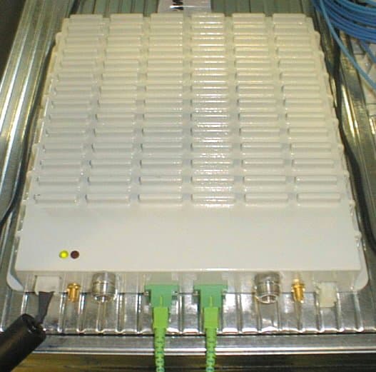
Click to zoom
Application Details
- Equipment Class
- PCB - PCS Licensed Transmitter
- Date of Grant
- Jun 24, 2004
- Application Purpose
- Original Equipment
- Date of Application
- Jun 24, 2004
- Equipment Note
- Model TFAM26 Downlink Booster
- Frequency Range
- 1930.00000000 - 1990.00000000
- Country
- United States
Documents & Files
Document Text
Text extracted from the exhibit documents filed with the FCC. Open a document above to read the original.
Users Manual
PLUS User Manual MN024-04 1 MN024-04 Copyright Tekmar Sistemi Srl Tekmar Sistemi Srl An Andrew Company Via De Crescenzi 40 48018 Faenza RA Tel: (+39) 0546 697111 Fax: (+39) 0546 682768 www.andrew.com This publication is issued to provide outline information and is not aimed to be part of any offer and contract. The Company has a policy of continuous product development and improvement and we therefore reserve the right to vary information quoted without prior notice. System and Customer care is available world-wide through our network of Experts. The company is certified ISO 9001 and ISO14000. 2 User Manual INDEX 1. Introducing Britecell Plus 5 1.1 The Features 6 1.2 Britecell Plus brief Description 6 1.3 Britecell Plus Features 7 1.4 Britecell Plus typical Applications 8 2. Equipment Overview 10 2.1. The Remote Unit TFAxxx and relevant TKA installation kit 11 2.2. The Britecell Plus Master Unit 12 2.3. Block diagrams 15 3. Remote Unit TFAxxx 18 4. Master Unit 32 4.1. 19” Subrack TPRNxy 33 4.2. Local Unit TFLN 47 4.3. 2-way splitter TLCN2 57 4.4. 4-way splitter TLCN4 60 4.5. RF diplexer TLDN 63 4.6. RF triplexer TLTN 66 4.7. RF duplexer THYN 69 4.8. RF attenuator TBSI 72 4.9. Digital RF attenuator TDI 75 4.10. Power limiter TMPx-10 79 5. Optional equipment and accessories 82 5.1. WLAN interface TWLI 83 5.2. Amplifier TWANx 86 5.3. WLAN booster TFBWx 89 5.4. Remote power supply TRS/TRSN 93 3 MN024-04 4 User Manual 1. Introducing Britecell Plus 5 MN024-04 1.1 The Features Britecell Plus is an innovative platform designed in order to provide an effective and flexible coverage to a large variety of indoor scenarios. Thanks to its high modularity, its low power consumption, and its full-transparency to protocols and modulation formats, Britecell Plus is the perfect plug&play solution to distribute any wireless standard (including GSM, GPRS, EDGE, CDMA, WCDMA, and WLAN IEEE 802.11b) to the in- building environments requiring reliable and interference-free communications, as well as high traffic capacity and maximum flexibility about future expansions. These unique features make the Britecell Plus platform suitable also for applications to critical areas experiencing difficulties in establishing and keeping phone calls, while its compact design always guarantees a minimum aesthetic impact. 1.2 Britecell Plus brief Description Britecell Plus is a Distributed Antenna System (DAS) based on the Radio-over-Fibre (RoF) technology, and capable of carrying wireless mobile signals through the 400 MHz- 2500 MHz frequency range regardless of their protocol and their modulation format. The system has two basic components, a Master Unit and a Remote Unit. The Master Unit is made of one or more subracks typically connected to the BTS (Base Tranceiver Station) through either a repeater (RF interface) or a coaxial cable. Each Remote Unit is connected with a dedicated pair of single-mode optical fibres (one for UL and one for DL) to the Master Unit. These optical fibres work on 1310 nm wavelenght and provide low losses and almost unlimited bandwidth, available for future system developments. Britecell Plus is a modular system whose basic components are: • one Master Unit made of one or more subracks, each providing 12 module slots. Each slot can host either an active or a RF passive device (chosen among the wide range of Britecell Plus options), in order to meet the planned design requirements; • a variable number of Remote Units (TFAxxx), whose function is feeding the antenna passive network; • a proper number of indoor antennas, suitable to provide radio coverage to the area. Britecell Plus is fully compatible with any type of indoor antennas; • the optical cables required to connect the 19” subracks to the TFAxxx. BTS TFLN 1 12 REMOTE UNIT 1 4 RF interface Two F.O. per RU Fig. 1: Britecell Plus system block diagram. 6 User Manual 1.3 Britecell Plus Features The following lines report a brief summary of Britecell Plus main features: • multiband 2G, 2.5G and 3G – 802.11b WLAN compatible: Britecell Plus is completely transparent to any transmission protocol and modulation format, and it can distribute any 2G, 2.5G, 3G wireless standard. In addition, a special option allows to carry also the WLAN (802.11b/g) service over the same infrastructure; • modular configuration for flexible design: by properly setting some parameters like the amount of RUs and the antenna locations, the Britecell Plus architecture can follow the environment specific features in order to obtain the most effective radio-coverage of the indoor area. The modularity of the system allows easy modifications for future growth and increasing traffic; • easy to install: the intelligent plug & play Britecell Plus system includes an Automatic Gain Control (AGC), that eliminates system gain variations regardless of optical loss. This avoids the need for field adjustments, thus reducing design, installation and optimization time. • low-power consumption: establishing a “quasi line-of-sight propagation” towards all mobile phones inside the area, Britecell Plus works with extremely low power levels. Low power levels have two great advantages: 1) allow mobile phones to work at lower power levels, thus limiting the radiated emissions and increasing their battery life; 2) allow a better control of interference effects between adiacent cells. • central supervision functions: all individual alarms of Britecell Plus system are stored in an internal flash memory, and available to both local and remote connections. Detailed alarm information is provided by special software (i.e. by Supervision or Maintenance software tools) running on a locally connected host, as well as any information about alarm status and alarm history is available to remote connections via TCP/IP protocols, SNMP agent, or HTTP servers. This alarm information is visible also by means of LEDs present on the front panels of both the MU and the RUs; • multiple-carriers system: there are no r…
Text truncated - open the document above for the full version.
Users Manual
2 6 Fig. 8: TKA layout with quote for wall anchors User Manual TFAxxx behaviour at system start-up Before the TFAxxx remote unit is switched on, make sure that: • the modules hosted by the Master unit have been connected each other with the RF jumpers, according to what has been planned in the system design • every TFLN local unit has been connected to its remote units • each remote unit has been connected to its coverage antennas For a correct system start-up, all the remote units are to be switched on before the Master Unit. For proper operations, the Master Unit can be turned on only when all the remote units are already on. Once the TFAxxx has been switched on, its behaviour can be summarized in the following steps: 1. when the Remote Unit is turned on, both the LEDs upon the warm side turn on for a couple of seconds 2. After that, the unit green LED remains on (thus indicating proper power supply), while the red LED switches off as soon as the Master Unit is turned on (meaning that DL optical power is OK and no alarms are present). 3. Once the Master Unit has been switched on, the status of both LEDs have to be as reported in table 2. In case the red LED remains on, please refer to the troubleshooting section. 4. After being switched on the remote unit starts working correctly. Anyway, in order to be recognized by the maintenance and supervision software, it is necessary for the corresponding TFLN local unit to carry out the discovery phase (please refer to Supervision System Manual for more details). During this phase which can last at max. 4min, depending on the system complexity, the TFLN LED ┌┘ blinks. Do not connect/disconnect any cable or any piece of equipment during the discovery phase! This may result in failing the identification of the remote unit. Led colour Status and Meaning Green ON (when power supply is on) Red OFF (when no major failure affects TFAxxx operations) TFAxxx troubleshooting Faults can be revealed by LEDS on the TFAxxx front panel as well as by LMT or supervision system (running on the agent) Both LMT and supervision system provide full information about the device causing the alarm. As a consequence, troubleshooting procedure can be very immediate when failure detection is directly carried out through LMT or supervision system. Britecell Plus modules are designed in order to exchange information so that each remote unit can receive failure notifications from its external equipment (e.g. a TFBW booster) through dry-contact connections. Moreover, the TFAxxx constantly monitors the optical signal received from its TFLN unit to control optical losses. The following table reports a brief description of alarms related to each remote unit, together with a reference to the corresponding alerted LEDs on the triple band remote unit front. Single band and dual band units have similar alarms, where applicable. Tab. 2: Status of TFAxxx LEDs in working conditions 2 7 MN024-04 Alarm description Red LED status Priority Failure on external equipment connected to dry-contact 1 On High Failure on external equipment connected to dry-contact 2 On High Internal power supply failure On High Breakdown in communications inside the TFAxxx board On High The optical power received on DL port is too low (ie, the AGC can no more compensate the optical losses on DL input signal) On High The optical power received on DL port is near to critical level, but the system still works (ie, AGC still compensates losses) No detection Low GSM DL power amplifier failure On High DCS DL power amplifier failure On High UMTS DL power amplifier failure On High Too high TFAxxx temperature No detection 1 Low Tab. 3: Alarm Description 1 This temperature alarm can be revealed by supervision or maintenance software if the TFAxxx board overheats. Keeping environmental conditions between +5°C and +40°.is an important key factor to get a proper TFAxxx temperature. As the table shows minor alarms (low priority alarms) are revealed only by LMT or supervision system, but not by LEDs. Minor alarms detect critical situations which should be checked and tested in order to avoid future possible system faults. Each remote unit is provided with an AGC system which comes in after the optical-to-RF conversion. This AGC can correctly compensate optical losses when these are estimated to be < 3 dB. In case optical losses are in the 3dB- 4dB range, the whole system still works, but AGC is near to its borderline levels. The red LED switches on when the estimated optical losses are > 4dB, the AGC not being able to compensate these losses any more. As shows in the previous table, the same red LED switches on to reveal any major failure. Following the troubleshooting procedure reported hereinafter it is possible to better understand what the problem is. Main troubleshooting procedure (The following procedure is summarized by the flow-chart in fig. 8) In case the red LED is ON, please follow these steps: 1. first of all, refer to dry-contact troubleshooting, so as to understand whether the alarm can depend on any external equipment failure (e.g. a TFBW booster failure) or not. 2. in case dry-contact troubleshooting has not revealed any failure, clean the optical adapter 3. if the problem still persists, refer to the fibre optic UL troubleshooting in order to check if optical cables or optical connections have any problem on UL path. 4. if previous action didn’t make the LED switch off replace the unit with a new one or contact for assistance. 2 8 User Manual Dry contact troubleshooting (The following procedure is summarized by the flow-chart in fig. 10) This procedure needs to be considered if at least one TFAxxx dry-contact is connected to some external equipment. If not, return to main troubleshooting procedure. Follow steps 1, 2 for each dry contact connected to any external equipment. These steps aim to detect any failure inside the external equipment or inside the dry-contact port. If dry-contacts don’t reveal equipment ma…
Text truncated - open the document above for the full version.
Users Manual
Then connect the UL and the DL RF cable (which come from a TBSI or a TLCN module, depending on how the system has been designed) to the TFLN UL and DL ports, respectively. Use a specific torque wrench to fix these RF cables to DL and UL ports. Remove the caps from TFLN optical ports and connect the SC-APC fibre optic cables to the ports. UL and DL cables coming from the same remote unit have to be connected to UL and DL ports marked by the same number on the TFLN front panel. As you switch on the system, carefully refer to the TFLN Start-Up section. Remember that remote units should be switched on before than the Master Unit in order to follow a correct Start-Up procedure. TFLN behaviour at system start-up Before the Master Unit is switched on, make sure that: • all expected modules have been inserted into the Master Unit • the modules have been connected each other by RF jumpers, according to what planned in the system design • every TFLN local unit has been connected to relevant remote units • each remote unit has been connected to its coverage antennas • the supervision agent, if present, has been connected to the Master Unit • different Master Units are connected each other via bus RS485 After that, remember that only when all the remote units are already on, the Master Unit itself can be turned on. Once the Master Unit has been switched on, the TFLN behaviour at system start-up can be summarized as per the following steps: 1. When Master Unit is turned on all the six LEDs upon the TFLN front panel go on for a couple of seconds. After that, the green LED remains on (indicating proper power supply) while the other LEDs indicate the local unit status, according to the following table. Note: In case unused optical ports of the TFLN have not been masked through LMT yet, corresponding LEDs will be on. If so, wait for the end of step 3 (discovery phase) then use LMT to mask them (please refer to relevant Application Note) 51 MN024-04 Label LED colour Status = Green ON (power supply is on) ┌┘ Red OFF (no major failure affects TFLN operations) 1 Red OFF (no major failure affects corresponding remote unit or UL connection) 2 Red OFF (no major failure affects corresponding remote unit or UL connection) 3 Red OFF (no major failure affects corresponding remote unit or UL connection) 4 Red OFF (no major failure affects corresponding remote unit or UL connection) Tab. 11: Status of the TFLN LEDs in full-working conditions 2. About 10 seconds after the system has been switched on, TFLN module begins a “discovery” phase to identify connected remote units. This operation is necessary to collect all the information to be provided to the supervision system. While the discovery phase is working, the TFLN general alarm (LED ┌┘) blinks while the other LEDs go on showing previously detected status. Time dedicated to discovery phase can be at maximum 4min and depends on system complexity. Do not connect/disconnect any cable or any piece of equipment during the discovery phase! This may result in failing the identification of remote units. Please note that, while the discovery phase is running, the whole system is working correctly. Discovery operations aim to collect information about remote units but they don’t affect the system functionality. 3. Once the discovery is finished, the TFLN general alarm (LED ┌┘) stops blinking and switches OFF. The power supply LED (green LED) remains on while LEDs 1,2,3,4 show either the status of the remote units or the quality of the UL connections. In case some of these LEDs remain on, check if they refer to unused optical ports or not. In case of unused TFLN ports use LMT to mask it otherwise if LED referring to a connected remote unit remains on, please refer to Troubleshooting procedure. Removing a TFLN module Switch off the Master Unit power supply, remove the SC-APC optical connectors, and insert the protection caps into TFLN optical ports. Then • unscrew the 4 screws and slowly remove the card. • put the removed TFLN card in its safety box. • switch on again the Master Unit power supply, and refer to Start Up section. 52 User Manual TFLN troubleshooting In case a TFLN local unit has any problem, this will be easily revealed through LEDs on TFLN front panels. Troubleshooting procedure can be easy when failure detection is directly carried out through LMT or supervision system, as an alternative, a manual troubleshooting procedure can be carried out. LEDs panel on TFLN front detect not only failures inside the TFLN, but they also reveals malfunctions located on related remote unit. The following table reports a brief description of the TFLN alarms, together with a reference to the corresponding alerted LEDs: Tab. 12: TFLN LEDs description As the table shows, LEDs on the TFLN front panel signal all high priority alarms while minor alarms, which detect critical situations which should be checked and tested in order to avoid future possible system faults, are only revealed by LMT or supervision system. Each TFLN is provided with an AGC system which compensates optical losses < 3 dB. TFLN LED alarms switch on when the estimated optical losses are > 4dB, the AGC not being able to compensate these losses any more. One of LEDs 1,2,3,4 might turn on not only to indicate a high optical loss detected by TFLN, but also to reveal a remote unit failure. Understanding the reason why one of LEDs 1,2,3 or 4 is on (a remote unit failure, an optical cable fault or an external equipment malfunction) can be done following the troubleshooting procedure reported hereinafter. Alarm description Alerted LED Alarm priority level The optical power received on UL port 1 is too low and the AGC can no more compensate the optical losses on UL port 1 1 High The optical power received on UL port 2 is too low and the AGC can no more compensate the optical losses on UL port 2 2 High The optical power received on UL port 3 is too low and the AGC can no more compensate the optical losses on UL port 3 3 H…
Text truncated - open the document above for the full version.
ID Label/Location Info
5 Vdc ; 6 A max WARNING! To prevent electrical shock do not remove the cover. Service by qualified personnel only. Model: BRITECELL ® PLUS Type: TFAM (Remote Unit Plus) Manufactured by: Tekmar Sistemi Srl An Andrew Company FCC ID: BCR-BCP-TFAM26 IC ID: 2237D-TFAM26
Internal Photos
TFAM26 PCB Pictures Figure 1 - TFAM26 Top With Shield Figure 2 - TFAM26 Top Without Shield Figure 3 - TFAM26 Bottom
Operational Description
Multi-Band, Multi-Operation Optical Distribution System PRODUCT SPECIFICATIONS Ultimate in-building coverage for airports, shopping malls, hotels conference centers, tunnels, corporate enterprises and high-rise buildings One Company. A World of Solutions. Britecell ® Plus Wireless operators have the ultimate solution for their indoor coverage and capacity problems with Britecell Plus from Andrew Corporation. Britecell Plus is a radio over fiber sys- tem that meets all distribution needs from the simplest to the most complex applications. This optical distribution system for wireless networks is capable of trans- porting frequencies from 800 MHz to 2500 MHz, from traditional cellular to wireless LAN signals. Using a unique design and transparent medium, Britecell Plus transports signals with near perfect integrity, regardless of protocol or modulation. Britecell Plus has two main components: a master unit and a remote unit. The master unit is collocated with the base station and connected via an RF interface (coaxial cable). Inside the master unit are various plug-in cards including RF-to-optical converters (local units), passive RF components, micro-controllers and power supply. RF signals are transported to the remote units over single mode fiber at 1310 nm. The remote units, which can be up to 3 km (about 2 miles) away, are avail- able in three different power classes and are designed to meet any distri- bution needs. The Britecell Plus intelligent plug-and- play system includes an Automatic Gain Control (AGC) that eliminates system g on, regardless of optical loss. This avoids field adjustments and reduces design, installation, and opti- mization time. • Tri-band modular system • Flexible radio network interface • Multiple power class remote units to meet any requirements • 3 km guaranteed optical link distance • Centralized system management interface • Easy to install and maintain • Infrastructure cost optimization Britecell ® Plus – System Specifications SPECIFICATIONS Frequency Frequency range, MHz SMR800Uplink . . . . . . . . . . .806 to 824 Downlink . . . . . . . . .851 to 869 CELL800Uplink . . . . . . . . . . .824 to 849 Downlink . . . . . . . . .869 to 894 GSM900Uplink . . . . . . . . . . .890 to 915 Downlink . . . . . . . . .935 to 960 EGSM900Uplink . . . . . . . . . . .880 to 915 Downlink . . . . . . . . .925 to 960 Britecell Plus System: Block Diagram Frequency range, MHz GSM1800Uplink . . . . . . . . . .1710 to 1785 Downlink . . . . . . . . .1805 to 1880 PCS1900Uplink . . . . . . . . . . .1850 to 1910 Downlink . . . . . . . . .1930 to 1990 UMTS2100Uplink . . . . . . . . . . .1920 to 1980 Downlink . . . . . . . . .2110 to 2170 Output power LOW POWERMEDIUM POWERHI POWER Output power per carrier, dBm Number of Carriers1 . . .2 . .4 .8 . . . . . . . . .1 . . .2 . .4 . .8. . . . . . . . . 1 . .2 . .4 . .8 iDEN, CDMA800 .16 . . .11.5 . .8 . . .4 . . . . . . . . .21 . . .17 . . . .13 . . .9. . . . . . . . . 31 . . .25 . . .23 . . .19 Analog, GSM800 .22 . . .14 . . . .12 . . .8 . . . . . . . . .27 . . .20 . . .17 . . .13. . . . . . . . 37 . . .30 . . .27 . . . .23 TDMA800 . . . . . .19 . . .12.5 . .10 . . .6 . . . . . . . . .24 . . . .18.5 . .15 . . .11. . . . . . . . 34 . . .26 . . .25 . . . 21 EDGE800 . . . . . . .18 . . .12 . . . .10 . . .6 . . . . . . . . .23 . . .18 . . . .15 . . .11. . . . . . . . 33 . . .25.5 . .25 . . .21 WCDMA800 . . . .12 . . .6 . . . . .1 . . . .-2 . . . . . . . . .17 . . . .11 . . . .6 . . . .3. . . . . . . . . 27 . . .21 . . .16 . . . .13 GSM900 . . . . . . .13 . . .10 . . . .7 . . . .4 . . . . . . . . .18 . . . .15 . . . .12 . . .9. . . . . . . . . EDGE900 . . . . . . .11 . . .8 . . . . .5 . . . .2 . . . . . . . . .16 . . .13 . . . .10 . . .7. . . . . . . . . . . GSM1800 . . . . . .13 . . .10 . . . .7 . . . .4 . . . . . . . . .20 . . .17 . . . . 14 . . .11. . . . . . . . . . . EDGE1800 . . . . . .11 . . .8 . . . .5 . . .2 . . . . . . . . .18 . . . .15 . . . .12 . . .9. . . . . . . . . . . TDMA1900 . . . . .18 . . .11.5 . . .9 . . .5 . . . . . . . . .24 . . . .18.5 .15 . . .11. . . . . . . . 34 . . .26 . . .25 . . .21 GSM1900 . . . . . .21 . . .13 . . . .11 . . .7 . . . . . . . . .27 . . .20 . . .17 . . .13. . . . . . . . 37 . .27.5 .27 . . .23 EDGE1900 . . . . . .17 . . .11 . . . .9 . . . .5 . . . . . . . . .23 . . .18 . . . .15 . . .11. . . . . . . . 33 . . .25.5 .25 . . .21 CDMA1900 . . . . .15 . . . 10.5 . .7 . . .3 . . . . . . . . .21 . . . .17 . . . .13 . . .9. . . . . . . . . 31 . . .25 . . .23 . . .19 WCDMA1900 . . .11 . . .5 . . . .0 . . .-3 . . . . . . . . .17 . . . .11 . . . .6 . . . .3. . . . . . . . . 27 . . .21 . . .16 . . . .13 CDMA2100 . . . . .19 . . .15 . . . .11 . . .7 . . . . . . . . .21 . . . .17 . . . .13 . . .9. . . . . . . . . WCDMA2100 . . . .15 . . .9 . . . .4 . . .1 . . . . . . . . .17 . . . .11 . . . .6 . . . .3 Britecell ® Plus – System Specifications SPECIFICATIONS System performance: 1 Local Unit + 1 Remote Unit LOW POWERMEDIUM POWER(*) HIGH POWER DOWNLINK Maximum composite RF input level, dBm . . . . . . . . . . . . . . . . . . .+10 . . . . . . . . . . . . .+10 . . . . . . . . . . .+10 RF gain, dB@800 MHz . . . . . . . . . . . . . .+14 . . . . . . . . . . . . .+20 . . . . . . . . . . .+27/25** @900 MHz . . . . . . . . . . . . . .+10 . . . . . . . . . . . . .+15 . . . . . . . . . . .- @1800 MHz . . . . . . . . . . . . . .+10 . . . . . . . . . . . . .+17 . . . . . . . . . . .- @1900 MHz . . . . . . . . . . . . . .+14 . . . . . . . . . . . . .+20 . . . . . . . . . . .+27 @2100 MHz . . . . . . . . . . . . . .+15** . . . . . . . . . . .+17 . . . . . . . . . . .- Flatness, dB . . . . . . . . . . . . . . . . . . . . . .±2 . . . . . . . . . . . . . .±2 . . . . . . . . . . . .±1 Output 1dB compression point, dBm @800,900, . . . . . . . . . . . . . .+22 . . . . . . . . . . . .+27 . . . . . . . . . . .+37/+34** @1800, 1900 MHz . . . . . . . . . . .+21 . . . . . . . . . . . .+27 . . . . . . . . . . .+37 @2100 MHz . . . . . . . . . …
Text truncated - open the document above for the full version.
Parts List/Tune Up Info
Pag.:DB115LP 27/05/041 Richiesta da : del Liv.Mod.900175000 TFAM2612/4 BC PLUS RU SMR800+PCS 3/05/04 NU 1,000 ----------------------------------------------------------------------------------------------------------------------------------- Livello|Componente |Variante|Descrizione/Ciclo |Um| Quantità |Pa|Oper.|IF Val|Ul.Var|Liv.Modifca | ----------------------------------------------------------------------------------------------------------------------------------- | |--------| | | | | | | | |03/05/04 | |--------| | | | | | | | |Rilasciata la rev.00 ||| ||||||||1 910135800 TFAMRF26 RF+OTT+FUS. TFAM SMR800+PCS NU1,00000 30504 ||| ||||||||-2 910135700 TFAMSB26 SCHEDA BASE TFAM SMR800+PCS NU1,00000 290304 ||| ||||||||--3 012700200 RETI RES.SMD 4,7 K 4I 1206 5% EXBV8V NU3,00000 170204 | |--------| | | | | | | | |AR2-3-4 ||| ||||||||--3 012700500 RETI RES.SMD 10 K 8B 1206 5% CAY17 NU1,00000 170204 | |--------| | | | | | | | |AR1 ||| ||||||||--3 435002400 COND.cer.chip 100nF 0603 50/63v X7R 10% NU73,00000 290304 | |--------| | | | | | | | |C1-2-3-4-8-9-12-13-14-16-17-18-19-21-23 | |--------| | | | | | | | |C29-30-37-39-46-47-48-50-52-58-59-60-63 | |--------| | | | | | | | |C64-74-81-82-83-85-87-88-89-93-99-100 | |--------| | | | | | | | |C101-102-104-107-109-152-154-158-159-160 | |--------| | | | | | | | |C174-178-180-183-184-185-186-187-188-255 | |--------| | | | | | | | |C256-260-262-263-264-293-309-345-391-399 | |--------| | | | | | | | |C434-440-442 ||| ||||||||--3 403010617 COND.elet.chip 10uF 16v 4x5.5 NACEW NU19,00000 170504 | |--------| | | | | | | | |C5-6-15-20-24-25-27-28-31-32-61-69-78-84 | |--------| | | | | | | | |C441-444-445-446-463 ||| ||||||||--3 444110500 COND.cer.chip 1uF 0805 16v X7R 20% NU36,00000 170204 | |--------| | | | | | | | |C7-33-42-54-55-56-57-65-67-70-71-117-124 | |--------| | | | | | | | |C138-142-153-166-200-234-240-271-273-279 | |--------| | | | | | | | |C314-344-354-357-359-366-394-409-411-418 | |--------| | | | | | | | |C425-439-448 ||| ||||||||--3 403010716 COND.elet.chip 100uF 16v 6.3x5.5 NACEW NU8,00000 170504 | |--------| | | | | | | | |C35-51-62-97-98-175-181-259 ||| ||||||||--3 445000500 COND.cer.chip 1nF 0603 50/63v COG 10% NU23,00000 290304 | |--------| | | | | | | | |C40-41-76-105-108-144-149-150-172-248 | |--------| | | | | | | | |C270-274-327-343-368-369-384-385-393-403 | |--------| | | | | | | | |C406-417-421 ||| ||||||||--3 402910716 COND.elet.chip 100uF 16v 6.3x6.3 NACZ NU2,00000 170204 | |--------| | | | | | | | |C26-36 ||| ||||||||--3 435000400 COND.cer.chip 100pF 0603 50/63v COG 5% NU101,00000 170504 | |--------| | | | | | | | |C43-110-111-112-113-115-116-118-119-120 | |--------| | | | | | | | |C121-126-127-132-133-134-145-147-148-164 | |--------| | | | | | | | |C167-169-170-171-173-198-203-204-214-217 | |--------| | | | | | | | |C221-224-229-230-231-232-233-238-239-241 | |--------| | | | | | | | |C242-243-244-246-249-250-251-267-269-272 | |--------| | | | | | | | |C275-278-288-289-292-295-305-308-317-318 | |--------| | | | | | | | | C319-321-329-332-333-334-335-336-337-338 | |--------| | | | | | | | |C339-340-346-348-349-352-358-363-364-367 | |--------| | | | | | | | |C380-388-389-390-392-404-405-407-412-414 | |--------| | | | | | | | |C415-416-419-420-422-423-424-427-428-452 | |--------| | | | | | | | |C460 ||| ||||||||--3 435001700 COND.cer.chip 470pF 0603 50/63v COG 5% NU5,00000 170204 | |--------| | | | | | | | |C22-72-90-94-161 ||| ||||||||--3 402915616 COND.elet.chip 15uF 16v 4x6.3 NACZ NU5,00000 170204 | |--------| | | | | | | | |C73-86-125-370-378 ||| ||||||||--3 435000300 COND.cer.chip 10pF 0603 50/63v COG 5% NU4,00000 170504 | |--------| | | | | | | | |C10-11-139-151 ||| ||||||||--3 435001300 COND.cer.chip 270pF 0603 50/63v COG 5% NU1,00000 70104 | |--------| | | | | | | | |C143 ||| ||||||||--3 445000800 COND.cer.chip 2,2nF 0603 50/63v X7R 10% NU1,00000 10103 | |--------| | | | | | | | |C80 Pag.:DB115LP 27/05/042 Richiesta da : del Liv.Mod.900175000 TFAM2612/4 BC PLUS RU SMR800+PCS 3/05/04 NU 1,000 ----------------------------------------------------------------------------------------------------------------------------------- Livello|Componente |Variante|Descrizione/Ciclo |Um| Quantità |Pa|Oper.|IF Val|Ul.Var|Liv.Modifca | ----------------------------------------------------------------------------------------------------------------------------------- ||| ||||||||--3 445000600 COND.cer.chip 10nF 0603 50/63v X7R 10% NU7,00000 290304 | |--------| | | | | | | | |C103-106-176-182-211-347-356 ||| ||||||||--3 435001600 COND.cer.chip 47pF 0603 50/63v COG 5% NU6,00000 10103 | |--------| | | | | | | | |C91-92-95-96-162-163 ||| ||||||||--3 455001600 COND.cer.chip 470nF 0603 16v Y5V 20% NU22,00000 290304 | |--------| | | | | | | | |C136-137-141-199-201-202-205-206-222-223 | |--------| | | | | | | | |C225-227-252-253-283-286-301-303-397-432 | |--------| | | | | | | | |C449-450 ||| ||||||||--3 435000600 COND.cer.chip 15pF 0603 50/63v COG 5% NU1,00000 290304 | |--------| | | | | | | | |C122 ||| ||||||||--3 435001400 COND.cer.chip 33pF 0603 50/63v COG 5% NU22,00000 290304 | |--------| | | | | | | | |C189-190-193-216-218-266-268-276-277-310 | |--------| | | | | | | | |C315-320-325-326-328-361-365-381-382-387 | |--------| | | | | | | | |C402-413 ||| ||||||||--3 435001400 COND.cer.chip 33pF 0603 50/63v COG 5% NU3,00000 MMS 180204 | |--------| | | | | | | | |C464-465-466 (lato bottom) ||| ||||||||--3 455000900 COND.cer.chip 1,5pF 0603 50/63v COG 20% NU1,00000 290304 | |--------| | | | | | | | |C304 ||| ||||||||--3 455000400 COND.cer.chip 2,2pF 0603 50/63v COG 20% NU1,000…
Text truncated - open the document above for the full version.
Contact Information
Applicant
Michael Shumate(Director, North American Operations)
Technical Contact
Non-Technical Contact
Nemko DallasDustin Oaks
[email protected]972-436-9600
Test Firm
Nemko Dallas, Inc.Michael Cantwell
Technical Specifications
| # | Rule Parts | Frequency Range | Power Output | Emission | Tolerance |
|---|---|---|---|---|---|
| 6 | 24E | 1.93 GHz - 1.99 GHz | 200.00 mW | G7W | Amp |
Other Applications from Andrew Wireless Innovations Group

BCR-IONEUAP
Mar 10, 2015ION-E
Equipment Class
B2I - Part 20 Industrial Booster (CMRS)
BCR-M17P26
Feb 08, 2012ION-M17P/26 EU
Equipment Class
TNB - Licensed Non-Broadcast Station Transmitter
BCR-TFAHUS717
Aug 14, 2011ION-B TFAH-US7/17
Equipment Class
TNB - Licensed Non-Broadcast Station Transmitter
BCR-TFAHUS4B
Jul 20, 2011ION-B TFAH-US4B
Equipment Class
PCB - PCS Licensed Transmitter
BCR-TFBM17
Jan 23, 2011ION-B TFBM17 FIBER OPTIC DISTRIBUTION REMOTE UNIT
Equipment Class
TNB - Licensed Non-Broadcast Station Transmitter